Sharp DV-NC150U User manual

1
DV-NC150U
S74W9DV-NC150
SERVICE MANUAL
In the interests of user-safety (Required by safety
regulations in some countries) the set should be
restored to its original condition and only parts
identical to those specified be used.
SERVICE MANUAL VCR/DVD COMBINATION MODEL DV-NC150U
VCR/DVD COMBINATION
This document has been published to be used for
after sales service only.
The contents are subject to change without notice.
SHARP CORPORATION
MAIN SECTION
1. SPECIFICATIONS ................................................................................................................................................ 1-1-1
2. LASER BEAM SAFETY PRECAUTIONS ............................................................................................................. 1-2-1
3. IMPORTANT SAFEGUARDS AND PRECAUTIONS............................................................................................ 1-3-1
4. STANDARD NOTES FOR SERVICING................................................................................................................ 1-4-1
5. PREPARATION FOR SERVICING ....................................................................................................................... 1-5-1
6. OPERATING CONTROLS AND FUNCTIONS...................................................................................................... 1-6-1
7. CABINET DISASSEMBLY INSTRUCTIONS ........................................................................................................ 1-7-1
8. ELECTRICAL ADJUSTMENT INSTRUCTIONS ................................................................................................... 1-8-1
9. FIRMWARE RENEWAL MODE (FIRMWARE VERSION UP) .............................................................................. 1-9-1
10. TROUBLESHOOTING ........................................................................................................................................ 1-10-1
11. BLOCK DIAGRAMS ............................................................................................................................................ 1-11-1
12. FUNCTION INDICATOR SYMBOLS................................................................................................................... 1-11-9
13. SCHEMATIC DIAGRAMS/ CBA’S AND TEST POINTS ..................................................................................... 1-12-1
14. WAVEFORMS & VOLTAGE CHART .................................................................................................................. 1-13-1
15. WIRING DIAGRAM ............................................................................................................................................. 1-14-1
16. SYSTEM CONTROL TIMING CHARTS.............................................................................................................. 1-15-1
17. IC PIN FUNCTION DESCRIPTIONS .................................................................................................................. 1-16-1
18. LEAD IDENTIFICATIONS ................................................................................................................................... 1-17-1
19. EXPLODED VIEWS ............................................................................................................................................ 1-18-1
20. MECHANICAL PARTS LIST ............................................................................................................................... N/A
21. ELECTRICAL PARTS LIST ................................................................................................................................ N/A
DECK MECHANISM SECTION
1. STANDARD MAINTENANCE ............................................................................................................................... 2-1-1
2. SERVICE FIXTURE AND TOOLS ........................................................................................................................ 2-2-1
3. MECHANICAL ALIGNMENT PROCEDURES ...................................................................................................... 2-3-1
4. DISASSEMBLY / ASSEMBLY PROCEDURES OF DECK MECHANISM ............................................................ 2-4-1
5. ALIGNMENT PROCEDURES OF MECHANISM .................................................................................................. 2-5-1
6. DECK EXPLODED VIEWS ................................................................................................................................... 2-6-1
7. DECK PARTS LIST............................................................................................................................................... N/A
CONTENTS
MODEL DV-NC150U
1The region number for this
VCR/DVD is 1.

MAIN SECTION
VCR/DVD COMBINATION
DV-NC150U
TABLE OF CONTENTS
1. SPECIFICATIONS .......................................................................................... 1-1-1
2. LASER BEAM SAFETY PRECAUTIONS ....................................................... 1-2-1
3. IMPORTANT SAFEGUARDS AND PRECAUTIONS ...................................... 1-3-1
4. STANDARD NOTES FOR SERVICING .......................................................... 1-4-1
5. PREPARATION FOR SERVICING ................................................................. 1-5-1
6. OPERATING CONTROLS AND FUNCTIONS................................................ 1-6-1
7. CABINET DISASSEMBLY INSTRUCTIONS .................................................. 1-7-1
8. ELECTRICAL ADJUSTMENT INSTRUCTIONS ............................................. 1-8-1
9. FIRMWARE RENEWAL MODE (FIRMWARE VERSION UP) ........................ 1-9-1
10. TROUBLESHOOTING .................................................................................. 1-10-1
11. BLOCK DIAGRAMS ...................................................................................... 1-11-1
12. FUNCTION INDICATOR SYMBOLS............................................................. 1-11-9
13. SCHEMATIC DIAGRAMS/ CBA’S AND TEST POINTS ............................... 1-12-1
14. WAVEFORMS & VOLTAGE CHART ............................................................ 1-13-1
15. WIRING DIAGRAM ....................................................................................... 1-14-1
16. SYSTEM CONTROL TIMING CHARTS........................................................ 1-15-1
17. IC PIN FUNCTION DESCRIPTIONS ............................................................ 1-16-1
18. LEAD IDENTIFICATIONS ............................................................................. 1-17-1
19. EXPLODED VIEWS ...................................................................................... 1-18-1
20. MECHANICAL PARTS LIST ......................................................................... 1-19-1
21. ELECTRICAL PARTS LIST........................................................................... 1-20-1

1-1-1 H9641SP
SPECIFICATIONS
Description Unit Minimum Nominal Maximum Remark
1. Video
1-1. Video Output (PB)Vp-p 0.8 1 1.2 9HSFL8A
9HSFL8M
W/O Burst
9HSFL8A
9HSFL8A
9HSFL8HA
1-2. Video Output (R/P)Vp-p 0.8 1 1.2
1-3. Video S/N Y (R/P)dB 40 45
1-4. Video Color S/NAM (R/P)dB 37 41
1-5. Video Color S/N PM (R/P)dB 30 36
1-6. Resolution (PB)Line 230 245
2. Servo
2-1. Jitter Low µsec 0.07 0.12
2-2. Wow & Flutter % 0.3 0.5
3. Normal Audio
3-1. Output (PB)dBV -9 -6 -3
3-2. Output (R/P)dBV -9 -6 -1.5
3-3. S/N (R/P)dB 36 41
3-4. Distortion (R/P)% 1.0 4
3-5. Freq. resp (R/P) at 200Hz (PB)dB -11 -4
(-20dB ref. 1kHz) at 8kHz
(PB)dB -14 -4
4. Tuner
4-1. Video output Vp-p 0.8 1 1.2
4-2. Video S/N dB 39 42
4-3. Audio output dB -10 -6 -2
4-4. Audio S/N dB 40 46
5. Hi-Fi Audio
5-1. Output (PB)dBV -12 -8 -4
5-2. Dynamic Range dB 70 85
5-3. Freq. resp (6dB B.W)Hz 20 ~ 20K
< VCR Section >
TAPE SPEED: SP
Notes:
1. Nominal specs represent the design specs. All units should be able to approximate these – some will exceed and
some may drop slightly below these specs. Limit specs represent the absolute worst condition that still might be
considered acceptable; In no case should a unit fail to meet limit specs.
2. For test tapes, refer to "SERVICE FIXTURE AND TOOLS" section.

1-1-2 H9641SP
NOTES:
1. All Items are measured without pre-emphasis unless otherwise specified.
2. Power supply : AC120 V ~ 60 Hz
3. Load imp. : 100 k ohm
4. Room ambient : 5 °C ~ 40 °C
5. Power consumption: 21 W (Standby: 3.6 W)
6. Weight: 6.0 lbs (2.7kg)
7. Dimension: 435 mm X 94 mm X 233 mm
ITEM CONDITIONS UNIT NOMINAL LIMIT
1 Video Output 75 ΩVpp 1.0 ±0.1
2 Coaxial Digital Out mVpp 500
3 Audio (PCM)
3-1. Output Level 1 kHz 0 dB Vrm 2.0
3-2. S/N dB 90
3-3. Freq. Response
DVD fs=48 kHz 20 ~ 22 kHz dB ±0.5
CD fs=44.1 kHz 20 ~ 22 kHz dB ±0.5
3-4. THD +N
DVD 1k Hz 0 dB % 0.008
CD 1k Hz 0 dB % 0.008
< DVD Section >

1-2-1 DVD_LASER
LASER BEAM SAFETY PRECAUTIONS
This DVD player uses a pickup that emits a laser beam.
Do not look directly at the laser beam coming
from the pickup or allow it to strike against
your skin.
The laser beam is emitted from the location shown in the figure. When checking the laser diode, be sure to keep your
eyes at least 30cm away from the pickup lens when the diode is turned on. Do not look directly at the laser beam.
Caution: Use of controls and adjustments, or doing procedures other than those specified herein, may result in
hazardous radiation exposure.
D
rive Mecha Assembly
Laser Beam Radiation
Laser Pickup
Turntable
LASER RADIATION
WHEN OPEN. DO NOT
STARE INTO BEAM.
CAUTION
Location: Top of DVD Mechanism

1-3-1 E56A0IMP
1. IMPORTANT SERVICE NOTES
BEFORE RETURNING THE DVD VIDEO PLAYER
Before returning the DVD video player to the user,
perform the following safety checks.
1. Inspect all lead dress to make certain that leads are
not pinched or that hardware is not lodged between
the chassis and other metal parts in the DVD video
player.
2. Inspect all protective devices such as non-metallic
control knobs, insulation materials, cabinet backs,
adjustment and compartment covers or shields, isola-
tion resistor/capacitor networks, mechanical insula-
tors etc.
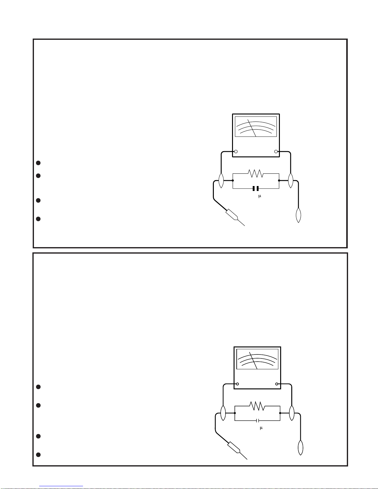
3. To be sure that no shock hazard exists, check for
current in the following manner.
Plug the AC line cord directly into a 120 volt AC outlet
(Do not use an isolation transformer for this test).
Using two clip leads, connect a 1.5k ohm, 10 watt
resistor paralleled by a 0.15µF capacitor in series with
all exposed metal cabinet parts and a known earth
ground, such as a water pipe or conduit.
UseanDVMor VOM with 1000 ohm per volt, or higher,
sensitivity or measure the AC voltage drop across the
resistor (See Diagram).
Move the resistor connection to earth exposed metal
part having a return path to the chassis (metal cabinet,
screw heads, knobs and control shafts, etc.) and
measure the AC voltage drop across the resistor.
Reverse the AC plug on the set and repeat AC voltage
measurements for each exposed part. Any reading of
0.45V rms (this corresponds to 0.3mA rms AC.) or
more is excessive and indicates a potential shock
hazard which must be corrected before returning the
DVD video player to the owner.
1. NOTES DE SERVICE IMPORTANTES
AVANT DE RENDRE LE REPRODUCTOR DE VíDEO
DVD
AvantderendrelereproductordevídeoDVDàl’utilisateur,
effectuer les vérifications de sécurité suivantes.
1. Vérifier toutes les gaines de fil pour être sûr que les fils
ne sont pas pincés ou que le matériel n’est pas coincé
entre le châssis et les autres pièces métalliques dans le
reproductor de vídeo DVD.
2. Vérifier tous les dispositifs de protection tels que les
boutons de commande non métalliques, les matériaux
d’isolement, le dos du coffret, les couvercles de
compartiment et ajustement ou les boucliers, les
réseaux de résistance / condensateur d’isolement, Ies
isolateurs mécaniques, etc.
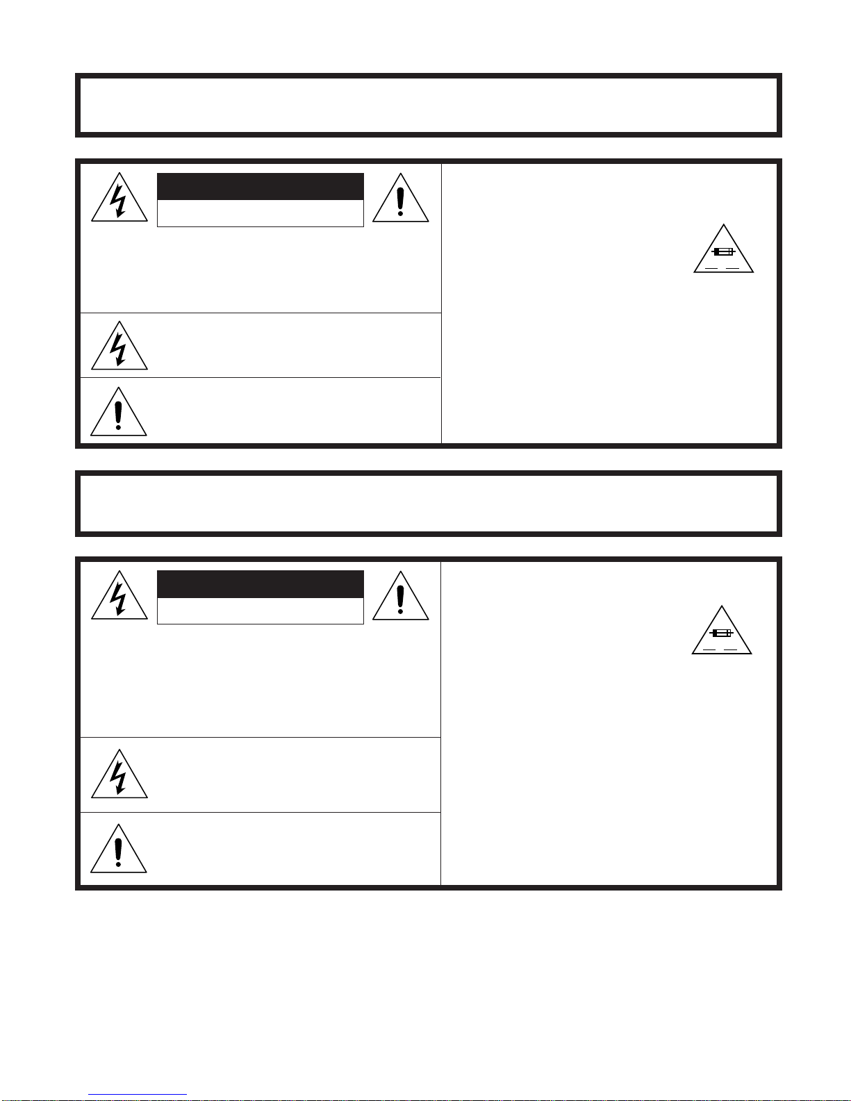
3. Pourêtresûrqu’iln’yaaucunrisquedechocélectrique,
vérifier le courant de fuite de la maniére suivante.
Brancher le cordon d’alimentation secteur directement
dans une prise de courant de 120 volts. (Ne pas utiliser
de transformateur d’isolement pour cet essai).
Utiliser deux fils à pinces et connecter une résistance
de10watts1,5kohmenparallèleavecuncondensateur
de0,15µFensérieavecdespiècesducoffretmétallique
exposées et une masse de terre connue telle qu’un
tuyau ou un conduit d’eau.
Utiliser un DVM ou VOM avec une sensibilité de 1000
ohms par volt ou plus ou mesurer la chute de tension
CA entre la résistance (voir diagramme).
Déposer la connexion de la résistance à toutes les
pièces métalliques exposées ayant un parcours de
retour au châssis (coffret métallique, tétes de vis, bou-
tons et arbres de commande, etc.) et mesurer la chute
de tension CA entre la résistance. Inverser la fiche CA
(une fiche intermédiaire non polarisée doit être utilisée
à seule fin de faire ces vérifications.) sur l’appareil et
répéter les mesures de tension CA pour chaque piéce
métallique exposée. Toute lecture de 0,45 V rms (ceci
correspond à 0,3 mA rms CA) ou plus est excessive et
signale un danger de choc qui doit être corrigé avant de
rendre le reproductor de vídeo DVD à son utilisateur.
IMPORTANT SAFEGUARDS AND PRECAUTIONS
SSVM
AC SCALE
1.5k ohms.
10W
0.15
TEST PROBE
T
O EXPOSED
M
ETAL PARTS
CONNECT TO
KNOWN EARTH
GROUNG
F
VTVM
AC SCALE
1.5k ohms
10W
CONNECT TO
KNOWN EARTH
GROUND
TO EXPOSED
METAL PARTS
TEST PROBE
0.15 F

1-3-2 E56A0IMP
WARNING :TOREDUCETHERISK OF FIRE OR ELECTRICSHOCK, DO NOT EXPOSE
THIS APPLIANCE TO WET LOCATIONS.
CAUTION: TO REDUCE THE RISK OF ELECTRIC
SHOCK. DO NOT REMOVE COVER. NO
USER·SERVICEABLE PARTS INSIDE.
REFER SERVICING TO QUALIFIED SERVICE
PERSONNEL.
CAUTION
This symbol mark means following.
For continued protection against fire
hazard, replace only with same type
fuse F1001 (1A, 250V) on MAIN
PWB.
RISK OF ELECTRIC SHOCK
DO NOT OPEN
This symbol alerts the user that there are
important operating and maintenance instruc-
tions in the literature accompanying this unit.
This symbol warns the user of uninsulated
voltage within the unit that can cause danger-
ous electric shocks.
ATTENTION:POURREDUIRELESRESQUESD'INCENDIEOUDECHOCELECTRIQUE,
NE PAS EXPOSER CET APPAREIL A LA PLUIE OU A L'HUMIDITE.
ATTENTION: AFIN DE REDUIRE LES RISQUES DE
CHOC ELECTRIQUE, NE PAS RETIRER LE
COUVERCLE, AUCUN ORGANE INTERNE
NE PEUT ETRE REPARE PAR
L'UTIUSATEUR, CONFIER L'APPAREIL A
UN DEPANNEUR QUALIFIE.
ATTENTION
Ce symbole signifie que l'on devra
utiliser un fusible de même type
F1001 (1A, 250V) on MAIN PWB.
Ce symbole signale à l'utilisateur la présence
d'unetensionnonisoléeàl'intérieurdel'appareil
qui peut être la cause de secousses électriques
dangereuses.
Ce symbole avertit l'utilisateur que des in-
structions importantes relatives à l'utilisation
et àl'entretien se trouvent dans le manuel
accompagnant l'appareil.
RISQUE DE CHOC ELECTRIQUE
NE PAS OUVRIR
CAUTION
ATTENTION
A V
F
A V
F

1-4-1 DVD_NOTE2
NOTE: CBA AND PWB MEANS PRINTED WIRING
BOARD.
Circuit Board Indications
a. The output pin of the 3 pin Regulator ICs is indicated
as shown.
Top View
Out In
Bottom View
Input
b. For other ICs, pin 1 and every fifth pin are indicated
as shown.
5
10
Pin 1
< Bottom View >
c. The 1st pin of every male connector is indicated as
shown.
Pin 1
< Bottom View >
Instructions for Connectors
1. When you connect or disconnect the FFC (Flexible
Foil Connector) cable, be sure to first disconnect the
AC cord.
2. FFC (Flexible Foil Connector) cable should be in-
serted parallel into the connector, not at an angle.
FFC Cable
Connector
CBA
* Be careful to avoid a short circuit.
Using lead-free wire solder
When fixing the PWB soldered with the lead-free solder,
apply lead-free wire solder. Repairing with conventional
lead wire solder may cause damage or accident due to
cracks.
As the melting point of lead-free solder (Sn-Ag-Cu) is
higherthantheleadwiresolder by 40°C,werecommend
you to use a dedicated soldering bit, if you are not
familiar with how to obtain lead-free wire solder or
soldering bit, contact our service station or service
branch in your area.
Soldering
As the melting point of lead-free solder (Sn-Ag-Cu) is
about 220°C which is higher than the conventional lead
solder by 40°C, and as it has poor solder wettability, you
may be apt to keep the soldering bit in contact with the
PWB for extended period of time. However, Since the
land may be peeled off or the maximum heat-resistance
temperature of parts may be exceeded, remove the bit
from the PWB as soon as you confirm the steady
soldering condition.
Lead-free solder contains more tin, and the end of the
soldering bit may be easily corroded. Make sure to turn
on and off the power of the bit as required.
If a different type of solder stays on the tip of the
soldering bit, it is alloyed with lead-free solder. Clean
the bit after every use of it.
When the tip of the soldering bit is blackened during
use, file it with steel wool or fine sandpaper.
Be careful when replacing parts with polarity indication
on the PWB silk.
Lead-free wire solder for servicing
STANDARD NOTES FOR SERVICING
Part No. Description Code
ZHNDAi123250E J 0.3mm 250g(1roll) BL
ZHNDAi126500E J 0.6mm 500g(1roll) BK
ZHNDAi12801KE J 1.0mm 1kg(1roll) BM

1-4-2 DVD_NOTE2
How to Remove / Install Flat Pack-IC
1. Removal
With Hot-Air Flat Pack-IC Desoldering Machine:
(1)Prepare the hot-air flat pack-IC desoldering ma-
chine, then apply hot air to the Flat Pack-IC (about 5
to 6 seconds). (Fig. S-1-1)
Fig. S-1-1
(2)Remove the flat pack-IC with tweezers while apply-
ing the hot air.
(3)Bottom of the flat pack-IC is fixed with glue to the
CBA; when removing entire flat pack-IC, first apply
soldering iron to center of the flat pack-IC and heat
up. Then remove (glue will be melted). (Fig. S-1-6)
(4)Release the flat pack-IC from the CBA using twee-
zers. (Fig. S-1-6)
Caution:
1. Do not supply hot air to the chip parts around the flat
pack-IC for over 6 seconds because damage to the
chip parts may occur. Put masking tape around the
flat pack-IC to protect other parts from damage.
(Fig. S-1-2)
2. The flat pack-IC on the CBA is affixed with glue, so
be careful not to break or damage the foil of each pin
or the solder lands under the IC when removing it.
Hot-air
Flat Pack-IC
Desoldering
Machine
CBA
Flat Pack-IC
Tweezers
Masking
Tape
Fig. S-1-2
With Soldering Iron:
(1)Using desoldering braid, remove the solder from all
pins of the flat pack-IC. When you use solder flux
which is applied to all pins of the flat pack-IC, you can
remove it easily. (Fig. S-1-3)
Flat Pack-IC Desoldering Braid
Soldering Iron
Fig. S-1-3
(2)Lift each lead of the flat pack-IC upward one by one,
using a sharp pin or wire to which solder will not
adhere (iron wire). When heating the pins, use a fine
tip soldering iron or a hot air desoldering machine.
(Fig. S-1-4)
Fine Tip
Soldering Iron
Sharp
Pin
Fig. S-1-4
(3)Bottom of the flat pack-IC is fixed with glue to the
CBA; when removing entire flat pack-IC, first apply
soldering iron to center of the flat pack-IC and heat
up. Then remove (glue will be melted). (Fig. S-1-6)
(4)Release the flat pack-IC from the CBA using twee-
zers. (Fig. S-1-6)
With Iron Wire:
(1)Using desoldering braid, remove the solder from all
pins of the flat pack-IC. When you use solder flux
which is applied to all pins of the flat pack-IC, you can
remove it easily. (Fig. S-1-3)
(2) Affix the wire to a workbench or solid mounting point,
as shown in Fig. S-1-5.
(3)While heating the pins using a fine tip soldering iron
or hot air blower, pull up the wire as the solder melts
so as to lift the IC leads from the CBA contact pads
as shown in Fig. S-1-5.

1-4-3 DVD_NOTE2
(4)Bottom of the flat pack-IC is fixed with glue to the
CBA; when removing entire flat pack-IC, first apply
soldering iron to center of the flat pack-IC and heat
up. Then remove (glue will be melted). (Fig. S-1-6)
(5)Release the flat pack-IC from the CBA using twee-
zers. (Fig. S-1-6)
Note:
When using a soldering iron, care must be taken to
ensure that the flat pack-IC is not being held by glue.
When the flat pack-IC is removed from the CBA,
handle it gently because it may be damaged if force
is applied.
To Solid
Mounting Point
Soldering Iron
Iron Wire
or
Hot Air Blower
Fig. S-1-5
Fine Tip
Soldeing Iron
CBA
Flat Pack-IC
Tweezers
Fig. S-1-6
2. Installation
(1)Using desoldering braid, remove the solder from the
foil of each pin of the flat pack-IC on the CBA so you
can install a replacement flat pack-IC more easily.
(2)The “ ” mark on the flat pack-IC indicates pin 1. (See
Fig. S-1-7.) Be sure this mark matches the 1 on the
PCB when positioning for installation. Then presol-
der the four corners of the flat pack-IC. (See Fig. S-
1-8.)
(3)Solder all pins of the flat pack-IC. Be sure that none
of the pins have solder bridges.
Example :
Pin 1 of the Flat Pack-IC
is indicated by a " " mark. Fig. S-1-7
Presolder
CBA
Flat Pack-IC
Fig. S-1-8

1-4-4 DVD_NOTE2
Instructions for Handling
Semi-conductors
Electrostatic breakdown of the semi-conductors may
occurduetoapotentialdifferencecausedbyelectrostatic
charge during unpacking or repair work.
1. Ground for Human Body
Be sure to wear a grounding band (1MΩ) that is properly
grounded to remove any static electricity that may be
charged on the body.
2. Ground for Workbench
Be sure to place a conductive sheet or copper plate with
proper grounding (1MΩ) on the workbench or other
surface, where the semi-conductors are to be placed.
Because the static electricity charge on clothing will not
escape through the body grounding band, be careful to
avoid contacting semi-conductors with your clothing.
CBA
< Incorrect >
CBA
Grounding Band
Conductive Sheet or
Copper Plate
< Correct >

1-5-1 H9641PFS
How to Enter the Service Mode
About Optical Sensors
Caution:
An optical sensor system is used for the Tape Start and
End Sensors on this equipment. Carefully read and
follow the instructions below. Otherwise the unit may
operate erratically.
What to do for preparation
Insert a tape into the Deck Mechanism Assembly and
press the PLAY button. The tape will be loaded into the
Deck Mechanism Assembly. Make sure the power is on,
connect TP502 (S-INH) to GND. This will stop the
function of Tape Start Sensor, Tape End Sensor and
Reel Sensors. (If these TPs are connected before
plugging in the unit, the function of the sensors will stay
valid.) See Fig. 1.
Note: Because the Tape End Sensors are inactive, do
not run a tape all the way to the start or the end of the
tape to avoid tape damage.
PREPARATION FOR SERVICING
Fig. 1
Q504
Q503
TP502 S-INH

1-6-1 H9641IB
OPERATING CONTROLS AND FUNCTIONS
DIGITAL
AUDIO OUT
COAXIAL
ANT-OUT
ANT-IN
ANT-OUT
ANT-IN
AUDIO
OUT
DVD V CR
DVD/VCR
S-VIDEO
OUT
COMPONENT
VIDEO OUT
AUDIO IN
VIDEO IN
AUDIO OUT
VIDEO OUT
L
LYL
RR
R
C
B
/
P
B
C
R
/
P
R
DIGITAL
AUDIO OUT
COAXIAL
AUDIO
OUT
DVD DVD/VCR VCR
S-VIDEO
OUT
COMPONENT
VIDEO OUT
AUDIO OUT
VIDEO OUT
AUDIO IN
VIDEO IN
L
L
Y
C
B/
PB
C
R/
PR
L
R
R
R
AUDIO IN jacks
Connect audio cables coming
from the audio out jacks of a
camcorder, another VCR, or
an audio source here.
DVD ANALOG AUDIO OUT
jacks
Connect the supplied audio
cables here through the Audio
In jacks of a television or other
audio equipment. (DVD only)
DVD/VCR AUDIO OUT jacks
Connect the supplied audio
cables here through the audio
In jacks of a television or other
audio equipment.
ANT IN jack
Connect your antenna
or cable box here.
ANT OUT jack
Connect the
supplied Round
Coaxial cable to
the antenna
input jack on
your TV.
DVD/VCR VIDEO OUT
jack
Connect the supplied yellow
video cable here through
the TV’s video in jack.
COAXIAL jack
Connect an optional coaxial
digital audio cable here
through the coaxial digital
audio in jack of a decoder or
audio receiver. (DVD only)
VIDEO IN jack
Connect a cable com-
ing from the video out
jack of a camcorder,
another VCR, or an
audio-visual source
(laser disc player, video
disc player, etc.) here.
S-VIDEO OUT jack
Connect an optional
S-Video cable here
through the S-video
in jack of a televi-
sion. (DVD only)
COMPONENT VIDEO
OUT jacks
Connect optional component
video cables here through
the component video in
jacks of a television.
(DVD only)
Front & Rear Terminals
REW FF
S
T
E
J
AV IN 2
VIDEO L(MONO)-AUDIO-R
[Back of VCR/DVD]
[Front of
VCR/DVD
]

1-6-2 H9641IB
VCR mode
DVD mode
DVD-V
DVD-V CD
CD MP3
MP3 VCR
VCR
Button
(Alphabetical order)
Disc/Tape
123
456
789
0 +10
ENTER
A
-
B
ANGLE
AUDIO
CLEAR/
C.RESET
DISPLAY
DVD
MENU
MODE
PLAY
POWER
REC/OTR
REPEAT
RETURN
SEARCH
MODE
SETUP
SLOW
SPEED
STOP
SUBTITLE
T-SET
TOP MENU
VCR
VCR/TV
ZOOM
PAUSE
SKIP/CH. SKIP/CH.
STOP
PLAY
123
456
789
0 +10
POWER SPEED AUDIO
DISPLAY
SKIP CH.
SLOW
VCR TV
PAUSE
REC OTR
ENTER
RETURN
TOP MENU
MENU
SETUP
CLEAR
C.RESET
ZOOM
MODE
SEARCH
MODE
A
-
B
ANGLE REPEAT
SUBTITLE
T-SET
DVDVCR
VCR
/
DVD COMBINATION
2
1
3
Installing the Batteries
for the Remote Control
I
nstall two AA batteries
(
supplied) matching the polarity indi-
c
ated inside battery compartment of
t
he remote control.
Remote Control
Within about
23 feet (7m)
Remote
control
K
eep in mind the following when using
t
he remote control:
Make sure that there is no obsta-
cle between the remote and the
remote sensor on the unit.
Use within the operating range
and angle, as shown.

1-6-3 H9641IB
CH
(TRACKING )
VCR OUTPUT DVD STOP PLAY
REW FF PLAY REC TIMER
STOP/
EJECT
POWER
OPEN/CLOSE
AV IN 2
VIDEO L(MONO)-AUDIO-R
DVD
Lights up when the inserted
disc is being played back.
Displays a type of the disc
which is inserted on the tray.
VD: DVD disc
Audio CD, MP3
Lights up when the
inserted disc comes
to a pause.
Lights up when the
A-B repeat function
is on.
Lights up when the
repeat function is on.
Lights up when playing back
in slow mode.(DVD)
Displays how long the current title
or track has been played back.When
a chapter or track is switched, the
number of a new title, chapter or
track is displayed.
Lights up when
the ALL repeat
function is on.
GROUP P .SCAN
DVD
CD
Lights up when the
progressive scan
system is activated.
MP3
MP3
CD
CD
DVD-V
DVD-V
Lights up when the inserted
cassette is being played
back.
Lights up when
the playback is
in still or slow mode.
Lights up during
playback when
the repeat function
is on.
Works as a tape counter(hour,minute,second)
.
Also displays a channel number,
tape speed, remaining time for OTR or
current time.
VCR REC
PM
Lights up
when a tape is
in the VCR/DVD.
Lights up when
the VCR/DVD is
in VCR position.
This light does not
appear when the
VCR/DVD is in
TV position.
Lights up during a recording.
Flashes when a recording
is paused.
Lights up when
current time is P.M.
Lights up when
the timer recording or an
OTR recording has been set
.
VCR
VCR
No disc inserted
/ cannot read disc
Opening the tray
Closing the tray
Loading the disc
When a disc or tape is
being played back
Front Panel Display
Lights up when power is on.
Timer light lights up when a
timer recording is set.
D
CD:

1-7-1 H9641DC
CABINET DISASSEMBLY INSTRUCTIONS
NOTE: CBA AND PWB MEANS PRINTED WIRING
BOARD.
1. Disassembly Flowchart
This flowchart indicates the disassembly steps to gain
access to item(s) to be serviced. When reassembling,
follow the steps in reverse order. Bend, route, and dress
the cables as they were originally.
1: Identification (location) No. of parts in the figures
2: Name of the part
3: Figure Number for reference
4: Identification of parts to be removed, unhooked,
unlocked, released, unplugged, unclamped, or de-
soldered.
P=Spring, L=Locking Tab, S=Screw,
CN=Connector,
*=Unhook, Unlock, Release, Unplug, or Desolder
e.g.5(S-1) = five Screws (S-1),
2(L-2) = two Locking Tabs (L-2)
5: Refer to "Reference Notes."
2. Disassembly Method
[1] Top Case
[2] Front Assembly
[3] Top Bracket
[4] DVD Mecha Assembly [7] DVD Main CBA Unit
[5] Partition Plate
[6] Loader Holder
[8] VCR Chassis Unit
[9] Deck Assembly
[10] DVD Open/Close CBA
[11] Power SW CBA
[12] Main CBA
↑↑↑ ↑ ↑
123 4 5
No.
LOC.
ID/
PART
REMOVAL
No.
Fig.
UNPLUG/DESOLDER
UNLOCK/RELEASE/
REMOVE/*UNHOOK/
Not
e
[1] Top Case D1 4(S-1)-
[2] Assembly
Front D2 *3(L-1), *3(L-2)1-2
1-1
1
[3] Bracket
Top D2 3(S-2)-
[4] Mecha
Assembly
DVD D3 *CN601
4(S-3), *CN401, -
[5] Plate
Partition D3 2(S-4)-
[6] Holder
Loader D3 2(S-5)-
[7] CBA Unit
DVD Main D4 *CN301
2(S-6), *CN201, 2-2
3
2-1
2
[8] Unit
Chassis
VCR D5 5(S-7), 2(S-8)-
[9] Assembly
Deck D6 (S-9), (S-10), (S-11)
Desolder, 4,5
[10]
Close CBA
DVD Open/
D6 Desolder -
[11] CBA
Power SW D6 Desolder
[12] Main CBA D6 ----------

1-7-2 H9641DC
Reference Notes
CAUTION 1: Locking Tabs (L-1) and (L-2) are fragile.
Be careful not to break them.
1-1. Release three Locking Tabs (L-1).
1-2. Release three Locking Tabs (L-2), then remove
the Front Assembly.
CAUTION 2: Electrostatic breakdown of the laser diode
in the optical system block may occur as a potential
difference caused by electrostatic charge accumulated
on cloth, human body etc., during unpacking or repair
work.
To avoid damage of pickup follow next procedures.
2-1. Disconnect Connector (CN301). Remove two
Screws (S-6) and lift the DVD Main CBA Unit.
(Fig. D4)
2-2. Short the three short lands of FPC cable with
solder before removing the FFC cable (CN201)
from it. If you disconnect the FFC cable (CN201),
thelaserdiodeof pickupwillbedestroyed. (Fig.D4)
CAUTION 3: When reassembling, confirm the FFC
cable (CN201) is connected completely. Then remove
the solder from the three short lands of FPC cable.
(Fig. D4)
4. When reassembling, solder wire jumpers as shown
in Fig. D6.
5. Before installing the Deck Assembly, be sure to
place the pin of LD-SW on Main CBA as shown in
Fig. D6. Then, install the Deck Assembly while
aligning the hole of Cam Gear with the pin of LD-SW,
the shaft of Cam Gear with the hole of LD-SW as
shown in Fig. D6.
(S-1)
[1]Top Case
Fig. D1
(S-2)
(S-2)
(L-1)
(L-2)
(L-1)
[2] Front
Assembly
[3]Top Bracket
Fig. D2
CN401CN601
(S-3)
(S-3)
(S-3)
(S-4)
(S-5)
[5] Partition Plate
[6] Loader
Holder
[4] DVD Mecha
Assembly
Fig. D3

1-7-3 H9641DC
CN201
CN301
(S-6)
[7] DVD Main
CBA Unit
DVD Mecha A
Fig. D4
(S-6)
View for A
Short the three short lands
by soldering.
(Either of two places.)
Short
lands
Short lands
FPC Cable
OR
Solder
Solder
(S-7)
(S-7)
(S-7)
(S-8)
(S-8)
[8]VCR Chassis Unit
Fig. D5

1-7-4 H9641DC
(S-9)
(S-10)
(S-11)
[12] Main CBA
[9] Deck Assembly
[10] DVD
Open/Close CBA
[11] Power
SW CBA
FE Head
Cylinder
AssemblyACE Head
Assembly
Desolder
Lead with
blue stripe
Desolder
Lead with blue stripe
From
FE Head
BOTTOMVIEW
Lead connections of Deck Assembly and Main CBA
Desolder
From
Capstan
Motor
Assembly
Printing side
Desolder
From
Cylinder
Assembly
From
ACE Head
Assembly Lead with
blue stripe
Lead with
blue stripe
Desolder
Lead with
red stripe
[12] Main CBA
SW512
LD-SW
LD-SW Pin
Hole
Hole
Shaft
Cam Gear
[12] Main CBA
[9] Deck Assembly
Pin
Fig. D6

1-7-5 H9641DC
HOW TO EJECT MANUALLY
1. Remove the Top Case, Front Assembly and Top Bracket.
2. Remove four Screws (S-3) in Fig. D3. Do not disconnect connectors.
3. While lifting up the DVD Mecha, rotate the roulette in the direction of the arrow as shown below.
4. Pull the tray slowly.
View for A
Rotate this roulette in
the direction of the arrow
A
DVD Mecha
Other manuals for DV-NC150U
1
Table of contents
Other Sharp VCR System manuals

Sharp
Sharp VC-FH30FPM User manual

Sharp
Sharp VC-AA370 User manual

Sharp
Sharp VC-MH770SM User manual

Sharp
Sharp VC-A592U User manual

Sharp
Sharp VC-FH300SM User manual

Sharp
Sharp VC-MH321HM User manual

Sharp
Sharp VC-A410U User manual

Sharp
Sharp VC-MH713HM User manual

Sharp
Sharp VC-581N User manual

Sharp
Sharp VC-MH761SM User manual

Sharp
Sharp VC-H818U User manual

Sharp
Sharp VC-MH703HM User manual

Sharp
Sharp VC-MH714HM User manual

Sharp
Sharp VC-MH80 User manual

Sharp
Sharp VC-H9888U User manual

Sharp
Sharp VC-A36X User manual

Sharp
Sharp VC-M333HM(S) User manual

Sharp
Sharp VC-A598U User manual

Sharp
Sharp VC-MH780BM User manual

Sharp
Sharp VC-MH71SM User manual