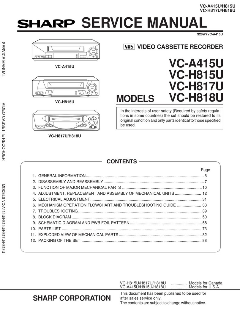
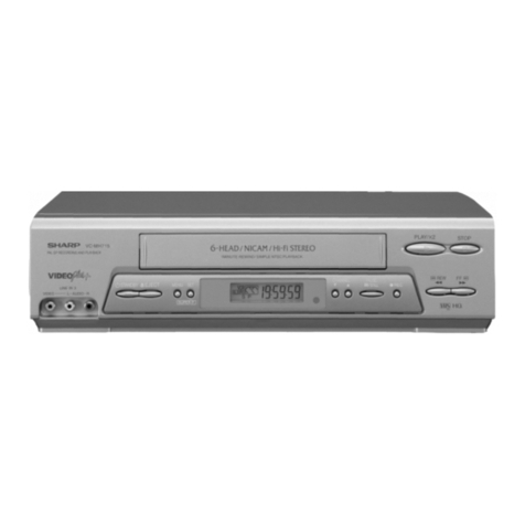
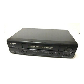
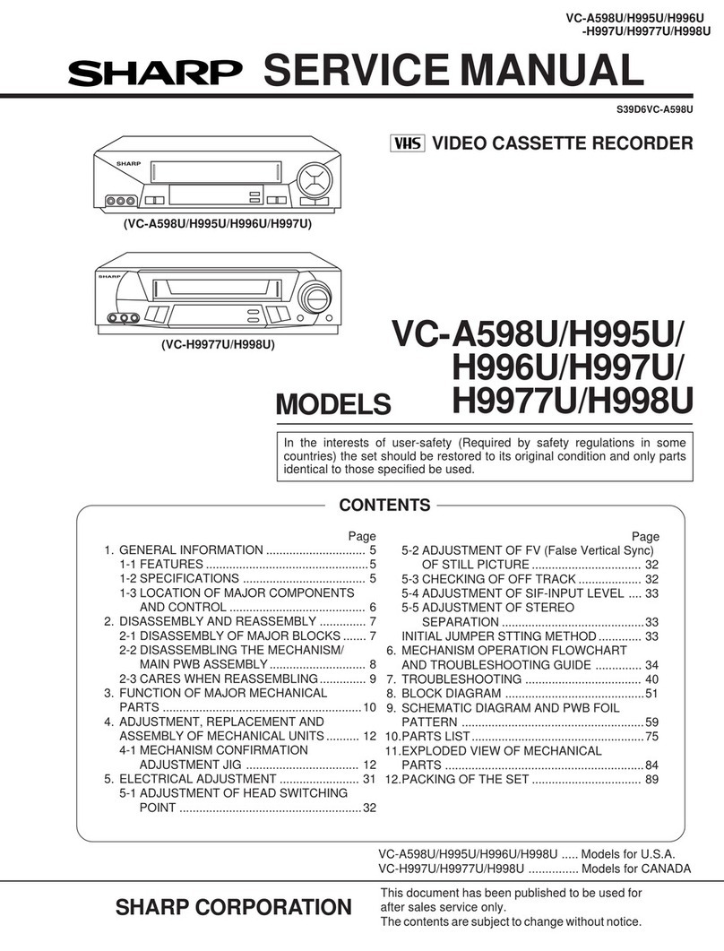
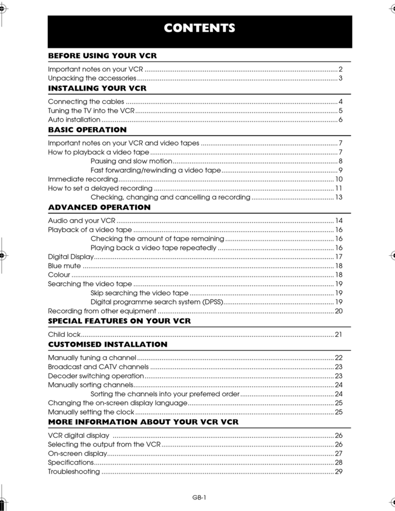
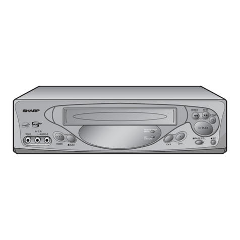
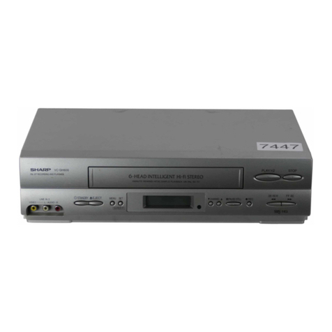
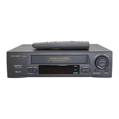
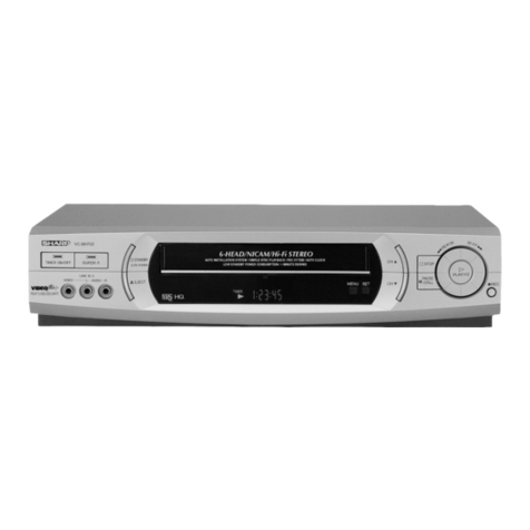
Sharp VC-A598U User manual

VC-A598U/H995U/H996U
-H997U/H9977U/H998U
1
SERVICEMANUAL
This document has been published to be used for
after sales service only.
Thecontentsaresubjecttochangewithoutnotice.
SHARP CORPORATION
VIDEO CASSETTE RECORDER
MODELS
In the interests of user-safety (Required by safety regulations in some
countries) the set should be restored to its original condition and only parts
identical to those specified be used.
VC-A598U/H995U/
H996U/H997U/
H9977U/H998U
CONTENTS
VC-A598U/H995U/H996U/H998U ..... Models for U.S.A.
VC-H997U/H9977U/H998U ............... Models for CANADA
(VC-A598U/H995U/H996U/H997U)
(VC-H9977U/H998U)
S39D6VC-A598U
Page
1. GENERAL INFORMATION .............................. 5
1-1 FEATURES.................................................5
1-2 SPECIFICATIONS ..................................... 5
1-3 LOCATION OF MAJOR COMPONENTS
AND CONTROL ......................................... 6
2. DISASSEMBLY AND REASSEMBLY .............. 7
2-1 DISASSEMBLY OF MAJOR BLOCKS....... 7
2-2 DISASSEMBLING THE MECHANISM/
MAIN PWB ASSEMBLY............................. 8
2-3 CARES WHEN REASSEMBLING.............. 9
3. FUNCTION OF MAJOR MECHANICAL
PARTS ............................................................10
4. ADJUSTMENT, REPLACEMENT AND
ASSEMBLY OF MECHANICAL UNITS.......... 12
4-1 MECHANISM CONFIRMATION
ADJUSTMENT JIG .................................. 12
5. ELECTRICAL ADJUSTMENT ........................ 31
5-1 ADJUSTMENT OF HEAD SWITCHING
POINT .......................................................32
Page
5-2 ADJUSTMENT OF FV (False Vertical Sync)
OF STILL PICTURE................................. 32
5-3 CHECKING OF OFF TRACK................... 32
5-4 ADJUSTMENT OF SIF-INPUT LEVEL .... 33
5-5 ADJUSTMENT OF STEREO
SEPARATION ...........................................33
INITIAL JUMPER STTING METHOD............. 33
6. MECHANISM OPERATION FLOWCHART
AND TROUBLESHOOTING GUIDE .............. 34
7. TROUBLESHOOTING ................................... 40
8. BLOCK DIAGRAM ..........................................51
9. SCHEMATIC DIAGRAM AND PWB FOIL
PATTERN .......................................................59
10.PARTS LIST....................................................75
11.EXPLODED VIEW OF MECHANICAL
PARTS ............................................................84
12.PACKING OF THE SET ................................. 89

VC-A598U/H995U/H996U
-H997U/H9977U/H998U
2
IMPORTANT SERVICE NOTES
WARNING :TOREDUCETHERISKOFFIREORELEC-
TRIC SHOCK, DO NOT EXPOSE THIS AP-
PLIANCE TO RAIN OR MOISTURE.
RISK OF ELECTRIC SHOCK
DO NOT OPEN
CAUTION
CAUTION: TO REDUCE THE RISK OF ELECTRIC SHOCK. DO
NOT REMOVE COVER. NO USER-SERVICEABLE
PARTS INSIDE. REFER SERVICING TO QUALIFIED
SERVICE PERSONNEL.
This symbol warns the user of uninsulated voltage
withintheunitthatcancausedangerouselectricshocks.
This symbol alerts the user that there are important
operatingandmaintenanceinstructionsintheliterature
accompanying this unit.
This symbol mark means fast operating fuse.
For continued protection against risk of fire, replace
only with same type fuse F901 (3.0A, 125V).
CAUTION:
BEFORE RETURNING THE VIDEO CASSETTE
RECORDER
Beforereturning thevideocassette recordertothe user,
perform the following safety checks.
1. Inspect all lead dress to make certain that leads are
not pinched or that hardware is not lodged between
thechassisandothermetalpartsinthevideocassette
recorder.
2. Inspect all protective devices such as non-metallic
control knobs, insulation materials, cabinet backs,
adjustmentandcompartmentcoversorshields,isola-
tion resistor/capacitor networks, mechanical insula-
tors etc.
3. To be sure that no shock hazard exists, check for
current in the following manner.
●Plug the AC line cord directly into a 120 volt AC outlet
(Do not use an isolation transformer for this test).
●Using two clip leads, connect a 1.5k ohm, 10 watt
resistorparalleledbya0.15µFcapacitorinserieswith
all exposed metal cabinet parts and a known earth
ground, such as a water pipe or conduit.
●Use an SSVM or VOM with 1000 ohm per volt, or
higher, sensitivity or measure the AC voltage drop
across the resistor (See Diagram).
●Move the resistor connection to earth exposed metal
part having a return path to the chassis (antenna,
metalcabinet,screwheads,knobsandcontrolshafts,
SSVM
AC SCALE
1.5k ohms.
10W
CONNECT TO
KNOWN EARTH
GROUND
TO EXPOSED
METAL PARTS
0.15 µF
TEST PROBE
etc.) and measure the AC voltage drop across the
resistor. Reverse the AC plug on the set and repeat
AC voltage measurements for each exposed part.
Anyreading of 0.45Vrms(this corresponds to0.3mA
rms AC.) or more is excessive and indicates a poten-
tial shock hazard which must be corrected before
returning the video cassette recorder to the owner.
3.0A 125V

VC-A598U/H995U/H996U
-H997U/H9977U/H998U
3
entrelarésistance.InverserlaficheCA(uneficheintermédiaire
non polarisée doit être utilisée à seule fin de faire ces
vérifications.) sur l’appareil et répéter les mesures de tension
CA pour chaque piéce métallique exposée. Toute lecture de
0,45 Vrms (ceci correspond à 0,3 mArms CA) ou plus est
excessive et signale un danger de choc qui doit être corrigé
avant de rendre le magnétoscope à son utilisateur.
NOTES DE SERVICE IMPORTANTES
ATTENTION: POUR REDUIRE LES RESQUES D'IN-
CENDIE OU DE CHOC ELECTRIQUE,
NE PAS EXPOSER CET APPAREIL A
LA PLUIE OU A L'HUMIDITE.
AVANT DE RENDRE LE MAGNETOSCOPE
Avant de rendre le magnétoscope à l’utilisateur, effectuer les
vérifications de sécurité suivantes.
1. Vérifiertoutes les gaines defilpour être sûr que lesfilsne sont
paspincés ou quelematériel n’est pascoincé entre le châssis
et les autres pièces métalliques dans le magnétoscope.
2. Vérifiertouslesdispositifsdeprotectiontelsquelesboutonsde
commande non métalliques, les matériaux d’isolement, le dos
ducoffret,lescouverclesdecompartimentetajustementoules
boucliers,lesréseauxderésistance/condensateurd’isolement,
Ies isolateurs mécaniques, etc.
3. Pourêtresûrqu’iln’yaaucunrisquedechocélectrique,vérifier
le courant de fuite de la maniére suivante.
●Brancher le cordon d’alimentation secteur directement dans
une prise de courant de 120 volts. (Ne pas utiliser de
transformateur d’isolement pour cet essai).
●Utiliser deux fils à pinces et connecter une résistance de 10
watts 1,5 kohm en parallèle avec un condensateur de 0,15 µF
ensérieavecdespiècesducoffretmétalliqueexposéesetune
masse de terre connue telle qu’un tuyau ou un conduit d’eau.
●Utiliser un VTVM ou VOM avec une sensibilité de 1000 ohms
par volt ou plus ou mesurer la chute de tension CA entre la
résistance (voir diagramme).
●Déposer la connexion de la résistance à toutes les pièces
métalliques exposées ayant un parcours de retour au châssis
(connexionsd’antenne,coffretmétallique,tétesdevis,boutons
etarbresdecommande,etc.)etmesurerlachutedetensionCA
RISQUE DE CHOC ELECTRIQUE
NE PAS OUVRIR
ATTENTION
Ce symbole avertit l'utilisateur que des instructions
importantesrelativesàl'utilisationetàl'entretiensetrouvent
dans le manuel accompagnant l'appareil.
ATTENTION: AFINDEREDUIRELESRISQUESDECHOCELECTRI-
QUE, NE PAS RETIRER LE COUVERCLE, AUCUN
ORGANE INTERNE NE PEUT ETRE REPARE PAR
L'UTILISATEUR. CONFIER L'APPAREIL A UN
DEPANNEUR QUALIFIE.
Ce symbole signale à l'utilisateur la présence d'une
tensionnonisoléeàl'intérieurdel'appareilquipeutêtrela
cause de secousses électriques dangereuses.
PRECAUTION:
Cette marque indique le fusible à action in stantansée.
Pourlaprotection continuecontrelerisque d'incendie,ne
remplacer que par le fusible type F901 (3A, 125V).
0,15 µF
SONDE D'ESSAI
VERS PIECES
METALLIQUES
EXPOSEES
VTVM
ECHELLE CA
1,5 KOHMS
10W
CANNECTER A
UNE MASSE DE
TERRE CONNUE
3A 125V

VC-A598U/H995U/H996U
-H997U/H9977U/H998U
4
PRECAUTIONS IN PART REPLACEMENT
When servicing the unit with power on, be careful to the section marked white all over.
This is the primary power circuit which is live.
When checking the soldering side in the tape travel mode, make sure first that the tape has been loaded and then turn
over the PWB with due care to the primary power circuit.
Make readjustment, if needed after replacement of part, with the mechanism and its PWB in position in the main frame.
(1) Start and end sensors: Q701 and Q702
Insert the sensor’s projection deep into the upper hole of the holder. Referring to the PWB, fix the sensors tight
enough.
(2) Photocoupler: IC901
Refer to the symbol on the PWB and the anode marking of the part.
(3) Cam switches A and B: D708 and D709.
Adjust the notch of the part to the white marker of the symbol on the PWB. Do not allow any looseness.
(4) Take-up and supply sensors: D707 and D706.
Be careful not to confuse the setting direction of the parts in reference to the symbols on the PWB. Do not allow any
looseness.

VC-A598U/H995U/H996U
-H997U/H9977U/H998U
5
1. GENERAL INFORMATION
1-1 FEATURES
1) Recording system Format: VHS NTSC Standard
Luminance signal: FM recording
Chroma signal: Low frequency converted direct recording
Color system: NTSC
Number of video head: 4
Tape speed: (SP) 33.35 mm/sec
(LP) 16.67 mm/sec
(EP) 11.12 mm/sec
2) Video signal Input level: 0.5 ~ 2.0 Vp-p, 75 ohm unbalanced
Output level: 1.0 Vp-p, 75 ohm unbalanced
Horizontal resolusion: 220 lines (SP mode)
Signal to noise ratio: 45dB (SP mode)
3) Audio signal Input level: – 8 dBs (309mVrms, 47k ohm)
Output level: – 8 dBs (309mVrms, 1k ohm)
Frequency response: 80Hz ~ 10kHz (SP mode linear)
Signal to noise ratio: 43dB (SP mode linear)
Hi-Fi dynamic range: 90dB
HI-Fi Frequency response: 20Hz ~ 20kHz
Hi-Fi Wow and flutter: 0.005% max. with T-120 tape
4) Receiving channel VHF: Channels 2 ~ 13
UHF: Channels 14 ~ 69
CATV: Channels A-8, A-5 ~ W + 84
Antenna Input Impedance: 75 ohm
5) Misc. Fast forward /Rewind time: Approximate 54 second with T-120 cassette
Power source: 120 V AC, 60 Hz
Power consumption: 20 W
Allowable ambient temperature: with T-120 tape 5°C to 40°C (41°F to 104°F)
Operating humidity: below 80% RH
Dimensions: 360 (W), 92 (H), 256 (D) mm(14-3/16, 3-5/8, 10-5/64 inch)(VC-A598U/H995U)
360 (W), 92 (H), 256 (D) mm(14-3/16, 3-5/8, 10-5/64 inch)
(Except VC-A598U/H995U)
Weight: 2.8 kg (6.17 lbs)
Accessories included: 75 ohm coaxial cable, Operation manual, Registration card
Infrared remote control, Dry Battery (2 pcs.)
Note: Specifications may be changed for improvement without notice.
1-2 SPECIFICATIONS
• High speed FF/REW (*400)
• EZ Set Up
• S-VHS Quasi Playback
• Double Azimuth 4-Head
•19
µm Clear Picture System (in EP Mode)
• HQ System for Better Resolusion and color Reproduc-
tion
• 3-Language OSD with Menu Screen Guidance
• 181-ch PLL Quartz Synthesized Random Access Tuner
with Automatic Channel Setting
• Quick Start with Full Loading Mechanism
• 1-Year, 8-Event Programmable Timer
• Simple Recording Timer
• SHARP Super Picture
• 20 seconds Timer Backup
• Field-Still/Variable Slow/Frame Advance
• Real-Time Counter
• Automatic Daylight Saving-Time (D.S.T.)Adjustment
• Blue Screen Noise Elimination
• Automatic Tracking Control System
• Digital Program Search System (DPSS)
• CM Skip Search
• Instant Replay
• Auto Zero Back
• Recorded Section Auto Repeat
• Full Automatic Playback
• Tamper Proof
• Up to 8 Hours of Recording/Playback (T-160)
• Automatic Head Cleaning System
• Built-in Front AV Jacks
• Built-in MTS (Multi-channel TV Sound) Detector
(Hi-Fi Models)
• Built-inShuttleControlSystem(Except VC-A598U/H995U)
• VCR Plus+ Programming System (Except VC-H996U/
H998U)
• VCR Plus+, C3Programming System (VC-H996U/H998U)
• Universal Remote Control: with Light-up Button (VC-
H997U/H9977U),withRemotePagerFunction(VC-H998U)
• Cable Box Channel Control Function/Digital Satellite
Receiver Control Function (VC-H996U/H998U)
VC-A598U/H995U/H996U
-H997U/H9977U/H998U
6
1-3 LOCATION OF MAJOR COMPONENTS AND CONTROL
Other manuals for VC-A598U
1
This manual suits for next models
5
Table of contents
Other Sharp VCR System manuals

Sharp
Sharp VC-581N User manual

Sharp
Sharp VC-M313HM User manual

Sharp
Sharp VC-MH705HM/LM User manual

Sharp
Sharp VC-A422U User manual

Sharp
Sharp vc-a260x User manual

Sharp
Sharp VC-MH714HM User manual

Sharp
Sharp VC-A50X User manual

Sharp
Sharp VC-A410X User manual

Sharp
Sharp VC-A310X User manual

Sharp
Sharp VC-MH80 User manual

Sharp
Sharp VC-A410U User manual

Sharp
Sharp XA-920 User manual

Sharp
Sharp VC-90ET User manual

Sharp
Sharp VC-M36GM Quick start guide

Sharp
Sharp VC-FH30GMS User manual

Sharp
Sharp VC-H992U User manual

Sharp
Sharp VC-A560U User manual

Sharp
Sharp VC-H730X User manual

Sharp
Sharp VC-MH835HM User manual

Sharp
Sharp VC-SA350 User manual