Shell NewMotion Business Pro View User manual

INSTRUCTION MANUAL – EN | INSTALLATIONSANLEITUNG - DE
INSTALLATION MANUAL
Business Pro View
Business Lite View
3,7 - 22 kW
VERSION 085NM19INT01


Table of contents /
Inhaltsverzeichnis
DE: +49 (0)30 215 028 48
Instruction manual (EN)
Pages 4 - 20
Installationsanleitung (DE)
Pagina 21 - 37
NewMotion
Business Lite & Pro View
3,7 - 22 kW

INSTALLATIEHANDLEIDING – P4 VERSION 0129NM02INT01INSTRUCTION MANUAL – P4 | P4 085NM19INT01
EN DE
1.1 PRODUCT DESCRIPTION &
INTENDED USE
Thank you for choosing a NewMotion Electric Vehicle
(EV) Charge Point.
This charge point is intended to charge the batteries within
EVs compatible with IEC-61851 MODE3 denition and
requirements. Dedicated EV specic plugs will need to be
utilised. No adaptors, conversion adaptors or extension
sets for cables are allowed to be used. EVs and cables
used with this charge point should always be undamaged
and in their original state.
This charge point is M&E-compliant, a Secured Mess
& Eichrecht Device (SMED) is build upon the existing
energy meter inside the charger. All legal relevant data
from each transaction is stored inside this device. It’s
possible for users to read and access live- and historical
data on the LED display screen.
1.2 SAFETY WARNING + CAUTION!
The electrical system must be voltage-free during the
entire installation procedure. Failing to do so can lead to
serious injury or even death. The installation procedure
must be carried out by a trained electrician who works in
accordance with all relevant local laws and regulations.
Do not install in potentially explosive atmospheres and/
or zones with high electromagnetic radiation and/or in
ood-prone areas.
The charge point is connected to the electricity grid
and even if the equipment is switched o, hazardous
voltages may be present at the input terminals. Always
switch o the AC supply before starting any work on
the charge point and/or its installation. Do not carry out
any work in rainy conditions or when the humidity is
above 95%. The safety guidelines are intended to ensure
correct installation and usage. Any failure to comply with
the valid safety guidelines or instructions provided in this
manual may result in re, electrocution or severe injury.
The charge point is a product in Safety Class I and is
supplied with an earth terminal for protection purposes.
The AC input clamps must be tted with an uninterruptible
earth for protection purposes. Ensure that the connection
cables are tted with fuses and circuit breakers. Never
replace a protection component with another type. First
check the full installation to determine if that component
can be used with the existing installation components.
Before you switch on the charge point, check that
the available power source matches the conguration
settings of the product, as described in this manual.
Tripping of the RCD could be caused by an earth fault
or a defect relay. If, after resetting the RCD, the device
cannot be activated or immediately trips again; please
contact NewMotion or your installer.
1.3 LEGAL DISCLAIMER
This manual is created for you with care.
We however do not guarantee that all information is
complete, accurate and correct. Please check our
website www.newmotion.com for the latest version
of this manual. We strongly advise you to have our
product installed by certied professionals. How our
product should be installed and used depends on
local circumstances and local and national regulation,
which are not mentioned in our manual. NewMotion
is not responsible for any loss or damage whatsoever
caused – including without limitation, any indirect,
personal or consequential loss or damage - arising
from or in connection with the use of this manual. Nor
does NewMotion accept any liability for any such loss or
damage arising out of your reliance on any information
contained in this manual.
1. INTRODUCTION

INSTALLATIEHANDLEIDING – P5 VERSION 0129NM02INT01INSTRUCTION MANUAL – P5 | P5 085NM19INT01
EN DE
To ensure the charge point is ready for use, the owner
needs to activate the charge point through our online
portal at my.newmotion.com. The serial number of the
charge point is needed for this process which can be
found on the right hand side of the charge point. Charge
cards can be activated in the same online portal.
2. ACTIVATING CHARGE POINT BEFORE USE

INSTALLATIEHANDLEIDING – P6 VERSION 0129NM02INT01INSTRUCTION MANUAL – P6 | P6 085NM19INT01
EN DE
Way of mounting
Standard: charge
point wall bracket
mounting
Optional pole
mounting
Optional concrete
base (for in soil) for
pole
Optional Wall bracket
for two NewMotion
charge points
Required tools & additional materials
(not provided)
- Installation materials (power cable and
cable mount clips, RCD(‘s), MCB(‘s), etc);
- Network switch (optional and not sold
by NewMotion);
- UTP cable(s) (CAT5 or CAT6);
- RJ45 UTP cable crimp tool;
- RJ45 connectors;
- 4 x screws (at least 6.3 x 60/70) and
plugs for mounting in wall;
- Drill and bit;
- Torx screwdrivers (T20 and T45);
- Voltage tester;
- Tape measure;
- Spirit level;
- All mentioned for standard mounting,
plus;
- Pole (sold separately);
- 4 x M8 wedge bolts or chemical
anchors, plus nuts and washers;
- All mentioned for pole mounting, plus;
- Concrete base (sold separately);
- DIN 912 HEX allen key (Size 6);
- Shovel;
- All mentioned for standard mounting,
plus;
- Pole (sold separately);
Package contents charge point
- Charge point;
- Wall bracket;
- Rubber grommets (various sizes);
- 2 x plastic spacers;
- Sticker sheet for the sides of the
charge point;
- 1 x M4 x 20 mm bolt (Torx);
- 6 x M4 x 12 mm bolts (Torx);
- 2 x M8 x 12 mm bolts (Torx);
- 4 x M8 x 12 mm bolts (Torx) plus
washers;
- 4 x M8 x 35 mm bolts (HEX DIN 912)
plus washers;
- 4 x M8 x 12 mm bolts (Torx) plus
washers;
3. PRODUCT OVERVIEW
3.1 MOUNTING OPTIONS, PACKAGE CONTENTS AND REQUIRED TOOLS

INSTALLATIEHANDLEIDING – P7 VERSION 0129NM02INT01INSTRUCTION MANUAL – P7 | P7 085NM19INT01
EN DE
3.2 TECHNICAL SPECIFICATIONS
3. PRODUCT OVERVIEW
Serial number format Business Pro View
Serial number format Business Lite View
Maximum number of Business Pro in one group
Models allowed in group
Maximum number of Business Lites per Business Pro
Maximum charge capacity
Standard congured charge capacity
Electric safety category
DC-fault current protection
Dimensions (H x W x D)
Weight
Standard colours
IEC-62262 IK code (robustness)
IEC-60529 IP code (protection class)
EN-50470 M-class
EN-50470 E-class
Certicates
kWh measurement
09 5_ _ _ _ _
08 5_ _ _ _ _
1
Business 2.0 and Business 2.1 chargepoints
Daisy chain conguration: 15
Star conguration: 40
1-phase 32A (7,4 kW)*
3-phase 32A (22kW)*
1-phase 16A (3,7kW)**
3-phase 16A (11kW)**
Class I & Class II****
Built-in 6mA DC fault current protection
503.5 x 200 x 137 mm
± 4.2 kg
Rear side RAL 7031 (grey)
Front side RAL 9010 (white)
IK10
IP54 (for indoor and outdoor use)
M1
E2
IEC-61851-1
IEC-61851-22
EV-Ready & ZE-Ready
IEC-62262 -> IK10
IEC-60529 -> IP54
IEC-62955 -> 6mA DC-fault protection
MessEV & MessEG
MID certied (accuraccy class B)
M&E certied

INSTALLATIEHANDLEIDING – P8 VERSION 0129NM02INT01INSTRUCTION MANUAL – P8 | P8 085NM19INT01
EN DE
* The maximum charge capacity of the charge point depends on several factors. This includes; local rules & regulations,
the type of EV, the grid connection at your location and the electricity usage of your building.
** Contact NewMotion for changing charge capacity
*** Contact NewMotion for further information: +44 20 3868 1036 and press option 1.
**** Product is tested and certied for both Class I & Class II. Method of mounting dictates which class is applicable;
Mounted on wall = Class II, mounted on the metal pole with Protective Earth connection = Class I.
3.2 TECHNICAL SPECIFICATIONS
3. PRODUCT OVERVIEW
User interface
Identication
Communication backoce (Pro View)
Communication backoce (Lite View)
Backoce protocol
Stand-by consumption
Operating temperature range
Operating humidity range
Operating air pressure range
Maximum mounting height socket
Advised mounting height socket
Mounting position
Function for ventilation according to IEC-61851
LED
LCD display
Proximity sensor-set
RFID (NFC) Mifare 13.56 MHz
IEC 14443A
IEC14443B
Plug & charge (through online portal)
GPRS 2G (minimal -80dBm Vodafone Partners)
Ethernet connection (DHCP, TCP 443, TCP80, TCP21)
2G/3G/4G with mobile router***
Ethernet connection with Pro (View)
OCPP protocol
3-6W
-30℃ to +40℃
5% to 95%
860 hPa to 1060 hPa
1.5 meter above ground
1 meter above ground
Vertical and upright position only
Not supported

INSTALLATIEHANDLEIDING – P9 VERSION 0129NM02INT01INSTRUCTION MANUAL – P9 | P9 085NM19INT01
EN DE
3.3 OVERVIEW OF PRODUCT
3. PRODUCT OVERVIEW

INSTALLATIEHANDLEIDING – P10 VERSION 0129NM02INT01INSTRUCTION MANUAL – P10 | P10 085NM19INT01
EN DE
If connecting to a 230V 3-phase grid without neutral; only install 1-phase and connect one of the two other phase
wires in the neutral wire connection on the terminal block.
3. PRODUCT OVERVIEW
3.4 OVERVIEW OF CONNECTIONS
INSIDE
INSIDE
Business Pro:
RJ45 UTP data port for
Ethernet / Mobile router
connection
Business Lite:
RJ45 UTP data port for
connection switch (star
conguration) or daisy
chain incoming
Earthing pole
for pole mount
UTP data cable
inlet with rubber
seal
UTP data cable inlet
with rubber seal
Inlet for power
cable with tension
relief clamps
Terminal block
SMED with LCD
user display &
Proximity
sensor-set
Tension relief for
data cable(s)
L1
N
PE (earthing)
Business Pro:
RJ45 UTP data port for
connection Switch in star
conguration or Business
Lites in Daisy chain
conguration
Business Lite:
RJ45 UTP data port for
daisy chain outgoing
DC-fault current
detection module
Business Pro:
RJ45 UTP data port for
Ethernet / Mobile router
connection
Business Lite:
RJ45 UTP data port for
connection switch (star
conguration) or daisy
chain incoming
Business Pro:
RJ45 UTP data port for
connection Switch in star
conguration or Business
Lites in Daisy chain
conguration
Business Lite:
RJ45 UTP data port for
daisy chain outgoing
Phase 2
Phase 3

INSTALLATIEHANDLEIDING – P11 VERSION 0129NM02INT01INSTRUCTION MANUAL – P11 | P11 085NM19INT01
EN DE
3. PRODUCT OVERVIEW
INSIDE
INSIDE
Business Pro:
RJ45 UTP data port for
Ethernet / Mobile router
connection
Business Lite:
RJ45 UTP data port for
connection switch (star
conguration) or daisy
chain incoming
Earthing pole
for pole mount
UTP data cable
inlet with rubber
seal
UTP data cable inlet
with rubber seal
Inlet for power
cable with tension
relief clamps
Terminal block
SMED with LCD
user display &
Proximity
sensor-set
Tension relief for
data cable(s)
L1
N
PE (earthing)
Business Pro:
RJ45 UTP data port for
connection Switch in star
conguration or Business
Lites in Daisy chain
conguration
Business Lite:
RJ45 UTP data port for
daisy chain outgoing
DC-fault current
detection module
Business Pro:
RJ45 UTP data port for
Ethernet / Mobile router
connection
Business Lite:
RJ45 UTP data port for
connection switch (star
conguration) or daisy
chain incoming
Business Pro:
RJ45 UTP data port for
connection Switch in star
conguration or Business
Lites in Daisy chain
conguration
Business Lite:
RJ45 UTP data port for
daisy chain outgoing
Phase 2
Phase 3
If connecting to a 230V 3-phase grid without neutral; only install 1-phase and connect one of the two other phase
wires in the neutral wire connection on the terminal block.

INSTALLATIEHANDLEIDING – P12 VERSION 0129NM02INT01INSTRUCTION MANUAL – P12 | P12 085NM19INT01
EN DE
3.5 BACKOFFICE CONNECTIONS
BUSINESS PRO (VIEW)
The Business Pro View can be connected to the
NewMotion backoce in three dierent ways:
1. Ethernet connection
2. GPRS 2G
3. 2/3/4G with NewMotion mobile router
The Business Pro View will connect to the NewMotion
backoce so settings can be changed remotely and
for remote support. Without the back oce connection
none of our online services can be used.
In groups of multiple Business charge points there
should be exactly one Business Pro (View). Connecting
a Business Pro (View) to another Business Pro (View) is
not possible.
3.5.1 BUSINESS PRO VIEW
– ETHERNET / NEWMOTION MOBILE ROUTER
Connecting the Business Pro View to ethernet or mobile
router can be done by connecting the network to the left
UTP Ethernet data port with a cable max 50 meter long.
Settings might have to be changed in the network
to allow the Business Pro View make a successful
connection to NewMotion backoce.
The network should have:
- DHCP
- Port TCP 80 and 443 should be opened
- FTP port 21 should be opened for the Business Pro
- All opened ports should be outbound
FTP is needed to update the rmware of the charge
point and exchange diagnostics.
3.5.2 BUSINESS PRO VIEW - GPRS 2G
The Business Pro View will rst attempt to connect
online through the left UTP Ethernet data port. If no
connection can be made the Business Pro View will try
to set up a GPRS connection. The connection will only
be possible if the signal strength is -80dBm or better for
Vodafone (or partners).
3.6 BUSINESS LITE VIEW -
BACKOFFICE CONNECTION
The Business Pro (View) will handle all communication
with the backoce for the Business Lites. This means
that a Business Lite (View) without being connected to a
Business Pro (View) will not connect to the NewMotion
backoce and remote settings can not be changed
or remote support can not be provided. Without the
backoce connection none of our online services can
be used.
The Business Lite (View) should, directly or indirectly,
be connected to the right hand side UTP data port of
a Business Pro (View). An indirect connection can be
through a switch or another Business Lite (Daisy chain).
3.6.1 BUSINESS LITE - DAISY CHAIN CONFIGURATION
The Business Lites have two ethernet ports which can
daisy chain the connection to the next Business Lite.
The left port should be closest to the Pro and the right
port should be going to the next Lite (see gure below).
The daisy chain conguration can be used up to
15 charge points. For higher quantities NewMotion
strongly recommends to use a star conguration. A star
conguration also limits possible downtime if that is
desired and can also be used to minimize downtime of
backoce connection and dynamic loadbalancing.
3.6.2 BUSINESS LITE - STAR CONFIGURATION
In a star conguration all Lites are connected from the
left UTP Ethernet data port to a switch.
From the right hand side of the Pro there is a cable going
to the same switch (please note that the left port of the
Pro is reserved for ethernet or mobile router connection,
see backoce connection business Pro). Only one Pro is
allowed to be connected to the switch.
3. PRODUCT OVERVIEW
(Mobile)
Router 09.......
(PRO)
Optional
(Mobile)
Router 09.......
(PRO)
Optional
(Mobile)
Router
Switch
08.......
(LITE)
08.......
(LITE)
08.......
(LITE)
08.......
(LITE)
09.......
(PRO)
08.......
(LITE)
08.......
(LITE)
08.......
(LITE)
08.......
(LITE)

INSTALLATIEHANDLEIDING – P13 VERSION 0129NM02INT01INSTRUCTION MANUAL – P13 | P13 085NM19INT01
EN DE
Wiring advice*
Power cable size
Earthing advice*
Required nominal
input voltage @
charge point
MCB
RCD
Ethernet connection
cable requirements
Ø 10mm - Ø 22,5mm
10mm2 solid wire
6mm2 stranded wire with end ferrules
PE-cable (PEN conductor is not allowed)
Separately installed grounding electrode
< 100 Ohm spreading resistance
230V +/-10% 50Hz
400V (3 x 230V+N) +/-10% 50Hz
Cable grommets sizes
Maximum cable terminal block
TN-system
TT-system
Single phase**
Triple phase**
4. INSTALLATION ADVICE
The electrician is responsible for selecting a cable thickness & safety components appropriate
for the specic situation and according to regulations;
* The electrician is always responsible for selecting a cable thickness appropriate for the specic
situation and according to regulations;
** 3-phase charge point can also be connected to 1-phase. In this case the charge point can only
charge on 1-phase;
*** The electrician must select a suitable MCB to match the amperage setting of the charge point,
taking into account MCB manufacturer specications;
NOTE: The charge point can be set between 10 A and 16 A / 32 A (depending on version);
- Wire for the maximum hardware amperage under continuous load;
- Calculate with a COS-Phi of 0.8;
- Calculate with a max allowable voltage drop over the cable of 2%;
- Use shielded cable for underground wiring;
C-characteristic***
30 mA Type A (HI, HPI, SI, KV), or 30 mA type B
Standard CAT5 or CAT6 Ethernet cable (UTP cable with RJ45 connectors)

INSTALLATIEHANDLEIDING – P14 VERSION 0129NM02INT01INSTRUCTION MANUAL – P14 | P14 085NM19INT01
EN DE
Thank you for installing this charge point.
Make sure there is enough space to properly do the work.
Ensure to work safely and take the safety of others into
consideration as well, always work according local
safety regulations.
When selecting the mounting location of the charge
point, make sure that future maintenance work can be
done easily.
5.1 PREPARATION
Step 1; Prepare the cabling (Power & UTP) & RCD and
MCB (conform to local rules & regulations);
Step 2; Indicate which circuit(s) the charge point is
connected to the distribution board;
Step 3; Attach the appropriate stickers provided
(1-phase or 3-phase) to the sides of the charge point in
the designated indent spaces;
Step 4; Turn the socket lid anti-clockwise and out of the
cover of the charge point;
Step 5; Then pull the cover from the rear edge to open the
charge point. Do not use any objects or tools to do this;
5.2 MECHANICAL MOUNT
For standard wall mount proceed with 5.2a, for optional
pole mount on pavement proceed with 5.2b, for optional
pole mount in soil proceed with 5.2c;
5.2A MECHANICAL MOUNT (WALL)
Step 1; Attach the wall bracket at the desired height (+/-
1 m height) on the wall;
Step 2; Put the charge point on the wall bracket to
check its placement. On the wall, mark the positioning
of the bottom two attachment points of the charge point
and select the appropriate xtures (plugs, screws and
washers).
Step 3; Secure the charge point to the wall bracket using
the two M8 x 12 mm bolts and washers provided.
Step 4; Secure the charge point to the wall using the
bottom two attachment points. Ensure that the grey
spacers are placed on the back of the charge point at
the bottom two attachment points.
5.2B MECHANICAL MOUNT (POLE ON
PAVEMENT)
Step 1; Drill holes into the pavement for the wedge bolts
or chemical anchors (not provided);
Step 2; Route the power cable(s) and UTP cable(s)
through the pole;
Step 3; Mount the wedge bolts or chemical anchor into
the pavement;
Step 4; Mount the pole to the threaded ends with
washers and nuts (not provided);
Step 5; Mount the green/yellow pole earthing wire to the
terminal block earthing connection;
Step 6; Secure the charge point to the pole bracket
using the four M8 x 12mm bolts and washers provided,
making sure to connect the pole earthing wire to the
bottom right bolt;
5.2C MECHANICAL MOUNT (POLE IN SOIL WITH
CONCRETE BASE)
Step 1; Dig the concrete base into the soil, make sure it
is steady and level;
Step 2; Route the power cable(s) and UTP cable(s)
through the pole;
Step 3; Mount the pole to the concrete base with the 4
bolts M8 x 35 and washers that are provided;
Step 4; Mount the green/yellow pole earthing wire to the
terminal block earthing connection;
Step 5; Secure the charge point to the pole bracket
using the four M8 x 12 mm bolts and washers provided,
making sure to connect the pole earthing wire to the
bottom right bolt;
5.3 POWER CONNECTION
Step 1; Select the appropriate grommet(s) that suits
the cable(s) thickness and place it in the opening of the
power cable inlet. Moisten if necessary to make it easier
to feed the power cable through;
Step 2; Secure the power cable(s) using the cable
clamp(s);
Step 3; Mount the (closed) black grommet in the
remaining cable inlet to make the charge point
watertight;
Step 4; Connect the power to the terminal blocks, like
indicated in the ‘overview of connections’ section;
5. INSTALLATION PROCEDURE

INSTALLATIEHANDLEIDING – P15 VERSION 0129NM02INT01INSTRUCTION MANUAL – P15 | P15 085NM19INT01
EN DE
5.4 COMMUNICATION CONNECTION PRO
VIEW
For UTP or NewMotion mobile router connection
(preferred) proceed with 5.4a, for GPRS connection
proceed with 5.4b; (refer to B.O. connections overview
3.4 & 3.5)
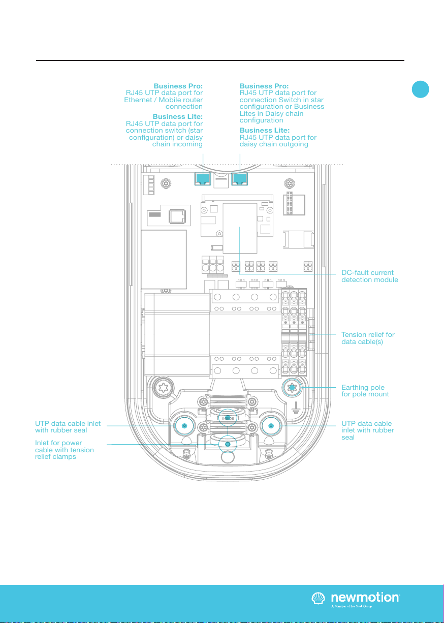
5.4A BUSINESS PRO VIEW COMMUNICATION
CONNECTION(S) (UTP)
Step 1; Feed the UTP cable(s) through the rubber
stop(s) on the data cable inlet and then connect it to
the left Ethernet port(s), like indicated in the ‘overview of
connections’ section;
Step 2; Connect the UTP cable to a internet enabled
router with DHCP or NewMotion mobile router;
5.4B BUSINESS PRO VIEW COMMUNICATION
CONNECTION(S) (GPRS)
Step 1; Check and make sure signal strength is
sucient;
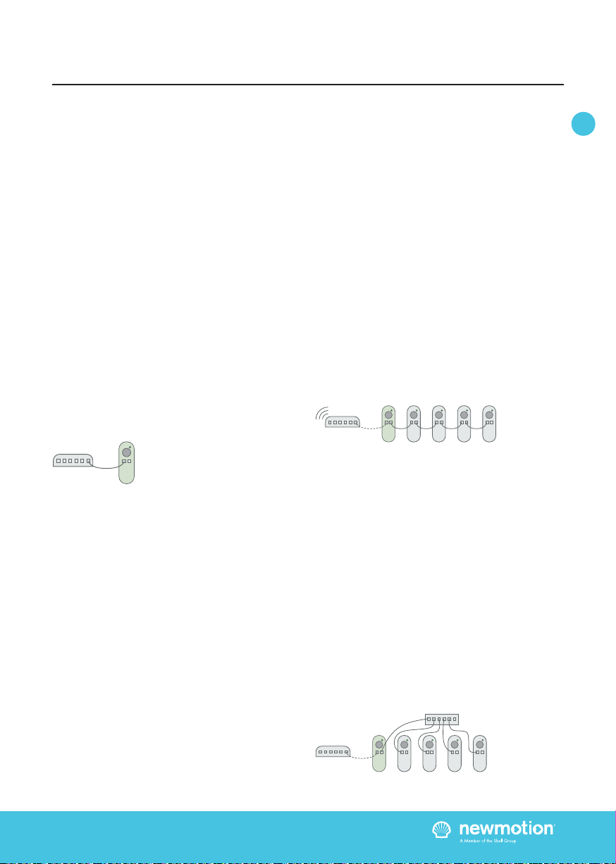
5.5 COMMUNICATION CONNECTION
BUSINESS LITE VIEW
For Daisy chain conguration proceed with 5.5a, for
Star conguration proceed with with 5.5b; (refer to 3.6
Business Lite - Backoce connection overview)
5.5A BUSINESS LITE VIEW COMMUNICATION
CONNECTION (DAISY CHAIN CONFIGURATION)
Step 1; Feed the UTP cable(s) through the rubber
stop(s) on the data cable inlet and then connect it to
the left Ethernet port(s), like indicated in the ‘overview
of connections’ section; The other end should be
connected to the right hand side Ethernet port of the
Business Pro;
Step 2: Feed a cable from right hand side port of the
Business Lite (View) to the left Ethernet port of the next
Business Lite (View); (Repeat step 2 till all Lites have
been connected)
5.5B BUSINESS LITE COMMUNICATION
CONNECTION (STAR CONFIGURATION)
Step 1; Business Pro (View): Feed a UTP cable(s)
through the rubber stop(s) on the data cable inlet and
then connect it to the right Ethernet port(s), like indicated
in the ‘overview of connections’ section;
Step 2: Business Pro (View): Connect the UTP cable to a
switch (no DHCP);
Step 3; Business Lite (View): Feed a UTP cable(s)
through the rubber stop(s) on the data cable inlet and
then connect it to the left Ethernet port(s), like indicated
in the ‘overview of connections’ section;
Step 4: Business Lite (View): Connect the UTP cable to
a switch (no DHCP);
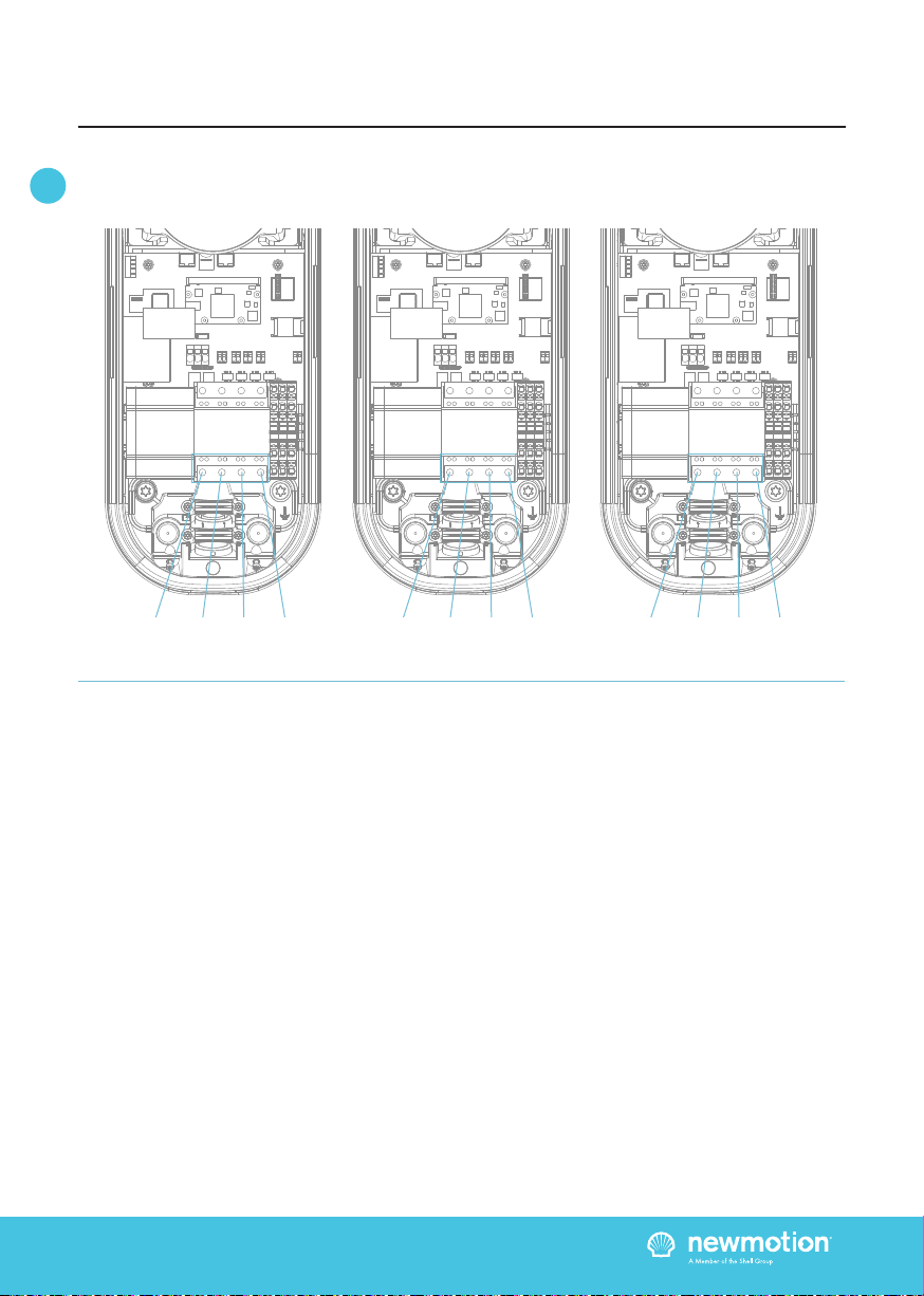
5.6 FINISHING UP (CLOSE ENCLOSURE)
Step 1; Check and make sure that the rubber (enclosure)
seal is properly in place on the edge (all around);
Step 2; Place the cover on the charge point;
Step 3; Hand-tighten the four M4 x 12 mm bolts
provided around the socket so that the cover closes on
the rubber seal but the rubber seal does not deform;
Step 4; Hand-tighten the other two M4 x 12 mm bolts
provided in the bottom of the cover;
Step 5; Turn the socket lid clockwise in the cover and
hand-tighten the M4 x 20 mm bolt provided;
Step 6; Switch on power to the charge point;
Step 7; Wait until charge point is fully started up (+/-10
minutes, LED should be o);
Step 8; Check that the business Pro (View) is connected
to the network. A quick check can be done online via
http://chargeportal.newmotion.com/test. Simply
enter the serial number into the search eld and click
“Search”. “Online” should appear after the serial number.
If ‘Online’ does not appear”, check whether the charge
point is properly connected and try again. For persistent
issues, please contact NewMotion.
Step 9; Check if the Business Lites are
connected online. Check all Business Lites on
http://chargeportal.newmotion.com/test. “Online”
should appear after entering the serial number. If ‘Online’
does not appear”, check whether the charge point is
properly connected and reset the Business Lites while the
Business Pro stays powered on. For persistent issues,
please contact NewMotion.
Step 10; If conguration of charge point power settings
is needed (for example lower Amp settings) please
contact NewMotion;
5. INSTALLATION PROCEDURE

INSTALLATIEHANDLEIDING – P16 VERSION 0129NM02INT01INSTRUCTION MANUAL – P16 | P16 085NM19INT01
EN DE
5. INSTALLATION PROCEDURE
5.7 CHECK FUNCTIONING
Step 1; Power on the chargepoint and let it start up (give
it a few minutes);
Step 2; Check start screen and connection, the display
should show the initial start screen as shown below;
Step 3; The date and time need to show up as grey
text. If it shows red text the SMED is not synchronised
(backoce connection issue) or not yet fully started up;
Step 4; You can refer to the user manual for more use
related instructions*;
*Alternatively the owner/operator manual can also be
consulted;

INSTALLATIEHANDLEIDING – P17 VERSION 0129NM02INT01INSTRUCTION MANUAL – P17 | P17 085NM19INT01
EN DE
For a successful installation of the Business Lite & Pro
charge points with Dynamic Power Sharing, the following
requirements need to be met:
- The group consists of one Business Pro and one or
more Business Lites
- All chargepoints are either Business 2.0
or Business 2.1
- All charge points are connected by UTP cables in a
either a daisychain or star conguration.
- All charge points should be online before the
conguration can be completed
- The available charge capacity for all charge points
combined is known
- The charge capacity for each charge point is known
- Phase rotation has to be applied according to
installation form (see 6.1)
The following is recommended:
- The installation is executed with 3-phase / 32 A power
cabling for each charge point.
- Ideally, there is at least 10 A per phase available per
charge point for the group at full occupancy
6.1 PHASE ROTATION (3-PHASE ONLY)
To make optimal use of the available power phase
rotations should be used. Beware, when this is not
correctly congured, Dynamic Power Sharing will not
work correctly and could result in overloading the grid
connection. Installation should be carried out, and
charge points should be connected, in accordance
with/to the installation procedure of this manual. The
phase rotation should be applied at the bottom of the
kWh meter. Put the L1 (Brown) and Neutral (Blue) always
in the terminal block.
The position in the installation form determines the
phase rotation the charge point will receive. There are
three dierent phase rotations which are used:
1. L1 L2 L3
2. L3 L1 L2
3. L2 L3 L1
Phase rotation L1 L2 L3 is the factory connection. To
change this to L2 L3 L1 or L3 L1 L2 loosen the three
left screws holding the power cables on the bottom.
Rearrange them and tighten the screws back up. Make
sure the power cables are rmly reapplied in the bottom
of the kWh meter. Failing to do so can result in re,
electrocution or severe injury.
The order for each phase rotation is as following:
6. OPTIONAL: DYNAMIC POWER SHARING
Description
Installation form /
Settings charge point
L1L 2L3
L3L1L2
L2L3L1
Order of power cables
located to the bottom
of charge point
(from left to right)
Brown, Black, Grey, Blue
Grey, Brown, Black, Blue
Black, Grey, Brown, Blue

INSTALLATIEHANDLEIDING – P18 VERSION 0129NM02INT01INSTRUCTION MANUAL – P18 | P18 085NM19INT01
EN DE
6. OPTIONAL: DYNAMIC POWER SHARING
L1 L2 L3 L3 L1 L2 L2 L3 L1
INSIDE
Brown Black Grey Blue
INSIDE
Grey Brown Black Blue
INSIDE
Black Grey Brown Blue

INSTALLATIEHANDLEIDING – P19 VERSION 0129NM02INT01INSTRUCTION MANUAL – P19 | P19 085NM19INT01
EN DE
6. OPTIONAL: DYNAMIC POWER SHARING
For this Dynamic Power Sharing conguration to be
successful, please follow and complete the form below
during the installation.
Keep this information handy when in contact with
the NewMotion support desk.
INSTALLATION FORM
Table 1. Installation form.
Position
1
2
3
4
5
6
7
8
9
10
11
12
Serial number
09 _ _ _ _ _ _
08 _ _ _ _ _ _
08 _ _ _ _ _ _
08 _ _ _ _ _ _
08 _ _ _ _ _ _
08 _ _ _ _ _ _
08 _ _ _ _ _ _
08 _ _ _ _ _ _
08 _ _ _ _ _ _
08 _ _ _ _ _ _
08 _ _ _ _ _ _
08 _ _ _ _ _ _
kWh meter inlets L1, L2, L3
Phase wire attached
L1
L3
L2
L1
L3
L2
L1
L3
L2
L1
L3
L2
L2
L1
L3
L2
L1
L3
L2
L1
L3
L2
L1
L3
L3
L2
L1
L3
L2
L1
L3
L2
L1
L3
L2
L1
Table 2. Information regarding the group charge capacity.
Charge capacity settings
Max amperage per phase
all charge points combined
Max amperage per phase
each charge point
CommentsValue (A)

INSTALLATIEHANDLEIDING – P20 VERSION 0129NM02INT01INSTRUCTION MANUAL – P20 | P20 085NM19INT01
EN DE
7.1 BEFORE USE: ACTIVATION &
REGISTRATION
To make the charge point ready for use the owner needs
to activate the charge point through our online portal
my.newmotion.com. The serial number of the charge
point is required for this process and can be found on the
right hand side of the charge point. Charge cards can be
activated in the same online portal.
7.2 REGULAR USE
Introduction to charging your EV:
First step is to connect your car to the charge point by
plugging in the charge cable.
If you are using Plug&Charge the session will start
automatically.
If you have to identify rst; swipe your charge card above
the LED.
First the LED will ash green to authenticate the card,
after authentication, the session will start. If the LED
ashes red, the session is not accepted.
When the car has delayed charging congured, the LED
will remain green, until charging can start from car and
charge point.
Start charging? Plug in & identify
Stop charging? Identify & unplug
Full or waiting to charge
Plug in or identify
Charging
Not accepted
Error
Flashing green or multi colors: starting procedure or
software update procedure for charge point.
7. PRODUCT USE / OPERATION
This manual suits for next models
1
Table of contents
Languages:
Other Shell Batteries Charger manuals

Shell
Shell SBC100 User manual

Shell
Shell newmotion Home Advanced Edition 7 User manual

Shell
Shell Recharge Advanced Flex Manual

Shell
Shell newmotion Business Pro View 2.2 User manual

Shell
Shell Saturn 2*22kW User manual

Shell
Shell Recharge Business Pro 3.0 User manual

Shell
Shell NewMotion Business Pro 2.1 User manual

Shell
Shell SBC400 User manual

Shell
Shell newmotion Home Advanced Edition 7 User manual

Shell
Shell SEV-32-01 User manual