Shell Saturn 2*22kW User manual

Shell Saturn 2*22kW (MID Version)
(EN) User Manual 1
(DE) Benutzerhan 14
(FR) Manuel de l'utilisateur 27
(NL) Gebruiksaanwijzing 40

User Manual
1
User Manual
Shell Saturn 2*22kW (MID Version)
EN

User Manual
2
Table of Contents
1 Instructions for Safety and Use.......................................................................................................................3
1.1 User group ................................................................................................................................................ 3
1.2 Precautions............................................................................................................................................... 3
1.3 Disposal....................................................................................................................................................4
1.4 Disclaimers...............................................................................................................................................4
2 Product Description........................................................................................................................................ 5
2.1 Overview of appearance ...........................................................................................................................5
2.1.1 Case B charging point with charging connector holder.....................................................................5
2.1.2 Case C charging point with charging connector cable ...................................................................... 6
2.2 Instructions for status indication .............................................................................................................. 6
3 Technical Parameters ......................................................................................................................................8
3.1 Product parameters ...................................................................................................................................9
3.2 Input parameters .......................................................................................................................................9
3.3 Output parameters of the charging point/method of connection with an electric vehicle ......................10
3.4 Protection parameters .............................................................................................................................10
3.5 Charging and access ............................................................................................................................... 10
3.6 Operating environment...........................................................................................................................10
3.7 Network communications .......................................................................................................................11
4 Installation & Commissioning & Maintenance Manual............................................................................12

User Manual
3
1 Instructions for Safety and Use
1.1 User group
The Saturn Charger is designed to charge electric vehicles. To ensure the normal use of charging sites,
please always obey the instructions in this Manual.
Only qualified electricians (partners authorized by Star Charge) are allowed to conduct installation,
debugging and maintenance. The qualified technicians must meet the following requirements:
Master the professional knowledge of all general and specific rules on safety and accident
prevention.
Understand the governing regulations related to electricity.
Be able to identify risks and avoid potential hazards.
1.2 Precautions
It is prohibited to use this product in the following situations:
There are inflammables and explosives nearby.
There is a water source near the installation position.
The product or an individual part is damaged.
Children or individuals who cannot properly assess the relevant risks arising from the use of this
product are able to use this product.
Star Charge does not assume any liability for any kind of damage and all warranties for products and
accessories are rendered void in the following situations:
The ambient temperature is lower than -25℃ or higher than 45℃.
The product is improperly installed, incorrectly used or poorly maintained’
The product has been disassembled, modified, or repaired.
Failure to comply with the installation, operation and maintenance manuals provided with this
product.
This product is used near flammables and explosives or in or near water.
There is a failure in the power distribution network.
Attention
Safety instructions are intended to ensure proper use. Failure to comply with these safety rules and
instructions may expose you to risks of electric shock, fire, or other serious personal injury
EN

User Manual
4
1.3 Disposal
Please classify different materials into recyclable materials, general waste and special waste before
disposal.
Please abide by local laws and regulations and relevant provisions while recycling or disposing of
products, individual components and packages.
Products with WEEE logos must be disposed of by delivering them to a place in which electrical
and electronic devices are separately collected.
1.4 Disclaimers
This document is provided for reference only and does not constitute a binding offer by Star
Charge.
Star Charge strives to ensure that the information it provides in its latest documents is as accurate as
possible, but makes no express or implied guarantee for its.
content or the completeness, accuracy, reliability or applicability of products and services provided
therein. Specifications and performance data are subject to change without prior notice.
Star Charge does not assume any liability for direct or indirect losses (including loss of profits)
incurred by any error or omission in this Manual. All obligations of Star Charge are stated in the
relevant contract agreements. Star Charge reserves the right to change this document at any time.
Please contact Star Charge to obtain the latest information and specifications before ordering.
Star Charge is committed to manufacturing high-quality products. This product has completely passed
the CE certification and meets the requirements of RED Directive 2014/53/EU and the Low Voltage
Directive 2014/35/EU. Further details can be found in the attached manual or by consulting your dealer or
service provider.

User Manual
5
2 Product Description
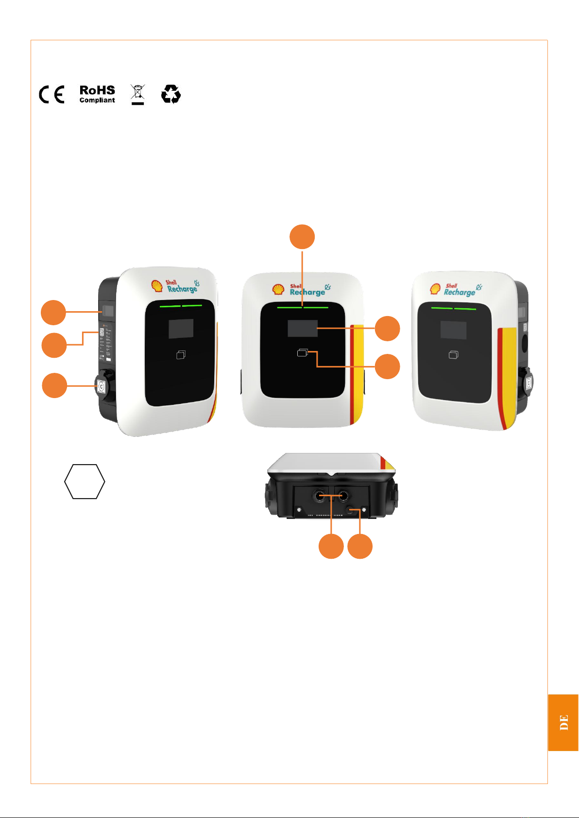
2.1 Overview of appearance
2.1.1 Case B charging point with charging connector holder
[1] —— LED status indicator
[2] —— 4.3-inch display screen
[3] —— RFID reader
[4] —— meter
[5] —— Nameplate
[6] —— Case B mode charging socket
[7] —— Sealed casings at the power cable
inlets
[8] —— Network cable interface
C
The label has been added to the protection cover of
case B mode (with charging connector holder) and
the charging connector head of case C mode (with
charging connector cable) according to EN
17186:2019 for easy identification
1
7
8
4
5
2
6
3
EN

User Manual
6
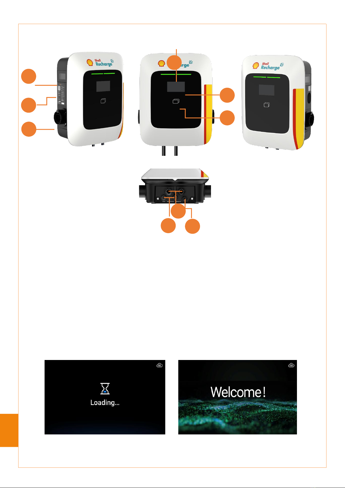
2.1.2 Case C charging point with charging connector cable
[1] ——LED status indicator
[2] —— 4.3-inch display screen
[3] —— RFID reader
[4] —— meter
[5] —— Nameplate
[6] —— Connector holder
[7] —— Sealed casings at the power cable
inlets
[8] —— Network cable interface
[9] —— Charging cable
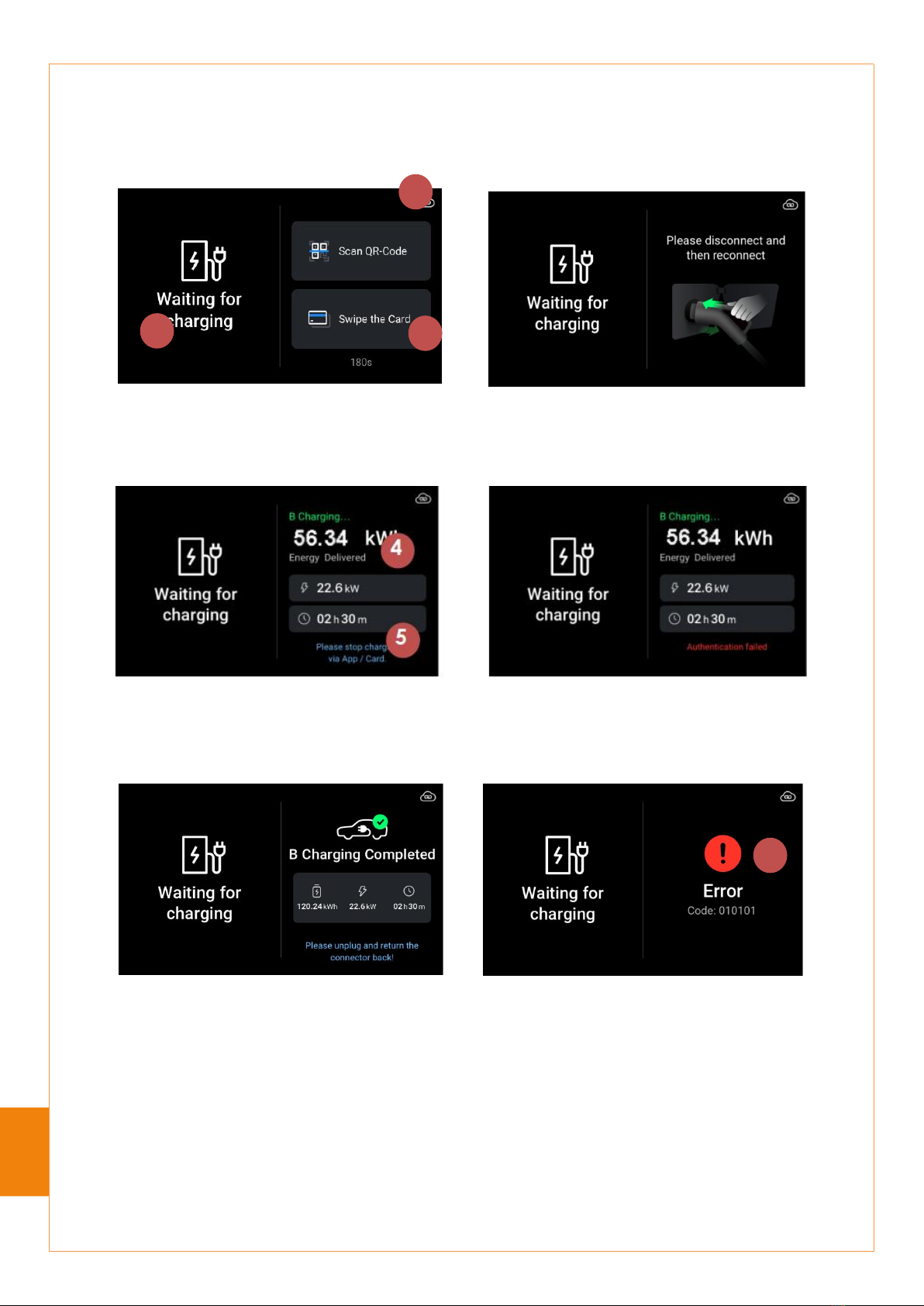
2.2 Instructions for status indication
The charging point is equipped with a color display screen to display the status of charging site.
The charging point is in loading status when started
The charging point is in standby status when no
connector is connected
1
5
2
6
3
4
7
9
8
User Manual
7
The vehicle connecting with the charging connector B is fully
charged
If the authentication for stopping charging connector B
from charging by swiping a card fails, please swipe
your card again (charging can be started and stopped
by swiping the same payment card)
A failure has occured in the charging area B, please
eliminate the failure before use
The vehicle connecting with the charging connector B
is being charged
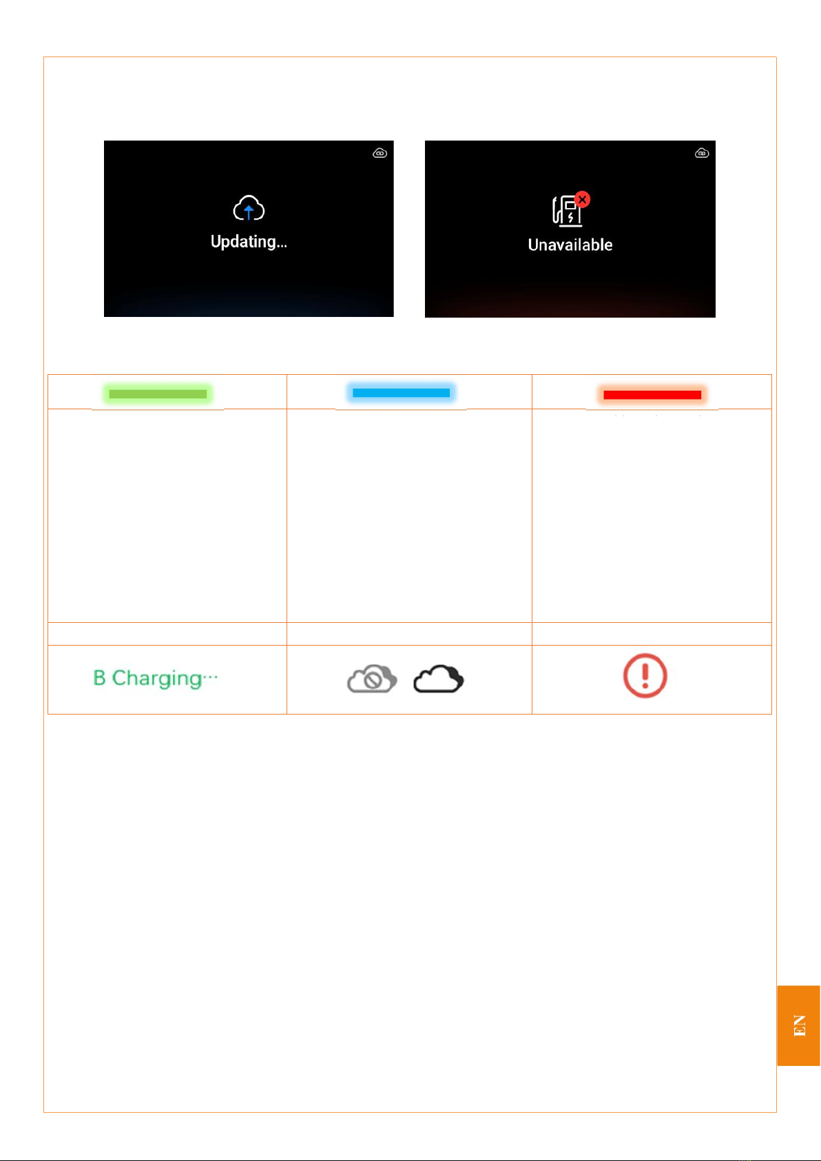
When the charging connector A is idle and the charging connector B is delivering energy, the status of
display screen in the charging process is as follows. The explanation of the icons is shown below:
1
2
3
Waiting for authentication. The charging connector B
has successfully connected with the point and the
vehicle
If the user’s authentication fails within 5min after the
charging connector B has successfully connected with the
point and the vehicle, please disconnect and then
reconnect the charging connector
6
[1] —— Online/offline
[2] —— Status display area of charging
connector A
[3] —— Status display area of charging
connector B
[4] —— Charging information (charging
power & charging time)
[5] —— A supplementary instruction for the
use by users is displayed here
[6] —— Failure notice with failure code
EN
User Manual
8
The updating and unavailable status of the charging point is displayed below. Please use the charging
point normally after it enters standby status:
LED status indication
The green lamp is on: The device is in
standby mode with no failures
1. The blue lamp is on: The charging
connector has been connected
2. The blue lamp flashes quickly: The
RFID card is being read
3. The blue lamp pulses: charging is in
progress
4. The blue lamp flashes slowly: The
vehicle suspends/the terminal suspends
(Suspend EV and suspend EVSE)
1. The red lamp is on: There is a
failure
2. The red lamp flashes quickly:
Authentication failed
3. The red lamp flashes slowly: The
card swiping or QR code scanning has
timed out and the charging connector
needs to be unplugged and plugged in
again
Charging in progress
Online/offline
Failure. A notice with failure codes
3 Technical Parameters
It applies to all vehicles that meet the IEC 62196-2 standard
The output power is configurable
The charging point supports the OCPP 1.6J communication protocol, that is, the charging point can
be connected to the OCPP 1.6J data service platform and management platform (cloud platform))
The charging point can be normally used in indoor and outdoor environments with protection levels
IP55 (Case C) and IP54 (Case B) and IK10
The device is equipped with the following protection functions:
- Lightning protection
- Overcurrent protection
- Short circuit protection
- Earth leakage protection
The charging point is in updating status
The charging point is in unavailable status

User Manual
9
- Overvoltage protection
- Undervoltage protection
- Grounding detection
- Tilt protection (optional)
3.1 Product parameters
Dimension (H x L x W)
505 mm×402 mm×197 mm
Weight
About 9.3kg
Installation method
Wall mounting/pole mounting
Certification
The device has passed the CE certification and meets the requirements of
RED Directive 2014/53/EU and Low Voltage Directive 2014/35/EU and the
following standards:
IEC 61851-1: 2019
IEC 61851-21-2: 2018
EN 300 328 V2.2.2
EN 300 330 V2.1.1
EN 301 908-1 V13.1.1
EN 301 908-2 V13.1.1
EN 301 908-13 V13.1.1
EN 301 511 V12.5.1
EN 301 489-1 V2.2.3
EN 301 489-3 V2.1.1
EN 301 489-17 V3.2.4
EN 301 489-52 V1.1.0
EN 50665:2017 & EN 62311: 2008
3.2 Input parameters
Recommended cable for the input
terminal
5 x 9AWG* (wire gauge 6mm2)
*It is recommended to crimp the adapter terminals on the power cable
conductor
Input wiring
3P + N for the power circuit
1P + N for the control circuit
Input rating
380-415 Vac for the power circuit
220-240 Vac for the control circuit
Input power limits
Single-connector, three-phase: maximum: 1 x 22 kW
Dual-connector, three-phase: maximum: 2 x 22 kW
Power rating
50/60 Hz
Grounding
TN-S、TT、IT
*Note: The supply circuit must not include a PEN conductor; a PME earthing
facility must not be used as for the protective conductor contact of a charging
point located outdoors.
Residual current protection
Type B RCCB
EN

User Manual
10
Standby power consumption
<15W
3.3 Output parameters of the charging point/method of connection with an electric
vehicle
3.4 Protection parameters
Leakage current protection
An independent Type B RCCB is equipped for each charging circuit
Meter
MID certification
Overcurrent protection
When the charging current reaches 110%-125% of the rated current, the circuit
will be cut off in 5s and the charging will be stopped
Once the charging current reaches more than 125% of rated current, the circuit
will be cut off immediately and the charging will be stopped
Overvoltage/undervoltage protection
Overvoltage protection: 269V
Undervoltage protection: 165V
Tilt protection (optional)
It is integrated in the mounting box of payment terminal
When the tilt of charging point in the direction of Z axis is greater than 30°, the
parent MCB of the charging point will be turned off immediately
3.5 Charging and access
Charging mode
Mode 3
Status indication
Displayed by display screen and indicated by LED lamp
Display
4.3’’ TFT color display; resolution: 800x480 pixels
Card reader
RFID (NFC) ISO 14443A/B, ISO 18092, ISO 15693 Mifare 13.56 MHz
Network communication
4G/ Ethernet/ Wi-Fi/ Bluebooth5.0
Communication protocol
OCPP 1.6 (JSON)
Background connection
ICU connection (optional) or other background systems (as required)
Communication with smart meter
RS485 port, Modbus protocol
Payment method
Payment by APP/payment by RFID card/payment by swiping a payment card
on the payment terminal (optional)
3.6 Operating environment
Operating temperature
-25°C - +45°C (natural cooling)
Maximum operating temperature:-30°C ~ +50°C
Storage temperature
-30°C - +85°C
Relative humidity
5% - 95% (no condensation)
Electrical safety level
I
Protection level
Case B (with charging connector holder): IP54; Case C (with charging
connector cable): IP55
Connection with vehicle
2 x type 2 sockets, in accordance with IEC62196-2
2 x type 2 connectors, in accordance with IEC62196-2
Output voltage
400V AC
Maximum charging current
Three-phase output, 32A per phase
Maximum output power
Single-connector, three-phase: maximum: 1 x 22 kW
Dual-connector, three-phase: maximum: 2 x 22 kW

User Manual
11
Anti-collision level
IK10
Attention
Your installation must be carried out in accordance with the standards and regulations of the region (country)
where the device is used. These forms are made according to the actual operating conditions of charging site
on the basis that all conditions are met, and the parameters included are recommended.
3.7 Network communications
4G module
Frequency band
Maximum radio-frequency power
LTE FDD Band 1
23±2.7dBm
LTE FDD Band 3
23±2.7dBm
LTE FDD Band 7
23±2.7dBm
LTE FDD Band 8
23±2.7dBm
LTE FDD Band 20
23±2.7dBm
WCDMA Band 1
24+1/-3dBm
WCDMA Band 8
24+1/-3dBm
GSM Band 3
33+2/-2dBm
GSM Band 8
30+2/-2dBm
WIFI module
Standard
IEEE 802.11 b/g/n, Wi-Fi compliant
Frequency
WLAN: 2.400GHz~2.497GHz
Transmission rate
802.11b: 1, 2, 5.5, 11Mbps
802.11g: 6, 9, 12, 18, 24, 36, 48, 54Mbps
802.11n: MCS 0-7 HT20
Bluetooth module
Standard
Bluetooth 2.1+Enhanced Data Rate (EDR) /Core Specification 5.1
Frequency range
2400-2483.5MHz
Output power
0 ≤ output power ≤ +10 dBm (conductive)
NFC module
NFC transmitting power: -2.59dBuA/m @ 3m
EN

User Manual
12
4 Installation & Commissioning & Maintenance Manual

User Manual
13
Contact / Contact / Kontakt/ Contact
EN

User Manual
14
Benutzerhan
dbuch
Shell Saturn 2*22kW (MID-Version)

User Manual
15
Katalog
1 Sicherheits- und Bedienhinweise ..................................................................................................................16
1.1 Zielgruppe..............................................................................................................................................................16
1.2 Sicherheitsvorkehrungen........................................................................................................................................16
1.3 Entsorgung.............................................................................................................................................................17
1.4 Haftungsausschlüsse.............................................................................................................................................. 17
2 Produktbeschreibung.................................................................................................................................... 18
2.1 Äußeres Erscheinungsbild..................................................................................................................................... 18
2.1.1 Ladestation (Gehäuse B) mit Ladeanschlusshalterung................................................................................... 18
2.1.2 Ladestation (Gehäuse C) mit Ladekabel.........................................................................................................19
2.2 Hinweise zu Statusanzeigen...................................................................................................................................19
3 Technische Spezifikationen.......................................................................................................................... 21
3.1 Produktdaten.......................................................................................................................................................... 22
3.2 Eingangsparameter.................................................................................................................................................22
3.3 Ausgangsparameter der Ladestationen/Anschlussmethode für Elektrofahrzeuge.................................................23
3.4 Produktdaten.......................................................................................................................................................... 23
3.5 Laden und Zugang................................................................................................................................................. 23
3.6 Betriebsumgebung................................................................................................................................................. 23
3.7 Netzwerkkommunikation.......................................................................................................................................24
4 Installations-, Inbetriebnahme- und Wartungshandbuch .............................................................................. 25
DE

User Manual
16
1 Sicherheits- und Bedienhinweise
1.1 Zielgruppe
Die Ladestation Saturn wurde für das Aufladen von Elektrofahrzeugen entwickelt. Um einen normalen
Betrieb der Ladestationen zu gewährleisten, befolgen Sie stets die Anweisungen in diesem Handbuch.
Nur qualifizierte Elektrofachkräfte (von Star Charge autorisierte Partner) dürfen die Installation,
Inbetriebnahme und Wartung der Ladestationen vornehmen. Die qualifizierten Elektrofachkräfte müssen die
folgenden Anforderungen erfüllen:
Beherrschung der Fachkenntnisse bezüglich aller allgemeinen und spezifischen Vorschriften zur
Sicherheit und Unfallverhütung,
Verständnis der gültigen Vorschriften in Bezug auf Elektrizität,
Fähigkeit zur Erkennung von Risiken und Vermeidung potenzieller Gefahren.
1.2 Sicherheitsvorkehrungen
Es ist untersagt, dieses Produkt in den folgenden Situationen zu verwenden:
wenn sich brennbare und explosive Stoffe in der Nähe befinden,
wenn sich eine Wasserquelle in der Nähe des Aufstellungsortes befindet,
wenn das Produkt oder eine einzelne Komponente beschädigt ist,
wenn sich Kinder oder Personen, welche die mit der Verwendung dieses Produkts verbundenen
Risiken nicht richtig einschätzen können, dieses Produkt verwenden.
Star Charge haftet nicht für Schäden jeglicher Art, und jegliche Garantie für Produkte und Zubehör
erlischt unter den folgenden Bedingungen:
Die Umgebungstemperatur ist niedriger als -25 °C oder höher als 45 °C.
Das Produkt wurde unsachgemäß installiert, wird unsachgemäß verwendet oder wird unsachgemäß
gewartet.
Das Produkt wurde demontiert, verändert oder repariert.
Die Installations-, Betriebs- und Wartungsanleitungen, die mit diesem Produkt mitgeliefert wurden,
werden nicht beachtet.
Dieses Produkt wird in der Nähe von brennbaren und explosiven Stoffen oder unter Wasser oder in
der Nähe von Wasser verwendet.
Es ist eine Störung im Stromverteilungsnetz vorhanden.

User Manual
17
Achtung
Die Sicherheitshinweise sollen eine ordnungsgemäße Verwendung gewährleisten. Bei Nichtbeachtung
dieser Sicherheitsvorschriften und -anweisungen besteht die Gefahr eines elektrischen Schlags, eines Brands
oder anderer schwerer Verletzungen.
1.3 Entsorgung
Trennen Sie die verschiedenen Materialien vor der Entsorgung in wiederverwertbare Materialien,
allgemeinen Abfall und Sondermüll.
Befolgen Sie bei der Wiederverwertung oder bei der Entsorgung von Produkten,
Einzelkomponenten und Verpackungen die lokalen Gesetze und Vorschriften sowie einschlägige
Bestimmungen.
Die Produkte mit WEEE-Logos müssen bei einer Entsorgungsstelle abgegeben werden, bei der
elektrische und elektronische Geräte getrennt gesammelt werden.
1.4 Haftungsausschlüsse
Dieses Dokument dient ausschließlich als Referenz und stellt kein verbindliches Angebot an Star
Charge dar.
Star Charge stellt eine aktuelle, möglichst präzise Fassung des Dokuments zur Verfügung und
übernimmt keine ausdrückliche oder stillschweigende Garantie
für deren Inhalt oder für die Vollständigkeit, Genauigkeit, Zuverlässigkeit oder Anwendbarkeit der
darin angebotenen Produkte und Services. Die Spezifikationen und Leistungsdaten können ohne
vorherige Ankündigung geändert werden.
Star Charge haftet nicht für direkte oder indirekte Verluste (einschließlich entgangenem Gewinn),
die aufgrund von Fehlern oder Auslassungen in diesem Handbuch entstehen. Alle Verpflichtungen
von Star Charge sind in den entsprechenden vertraglichen Vereinbarungen festgelegt. Star Charge
behält sich das Recht vor, dieses Dokument von Zeit zu Zeit zu überarbeiten.
Wenden Sie sich vor der Bestellung an Star Charge, um die neuesten Informationen und
Spezifikationen zu erhalten.
Star Charge strebt danach, hochwertige Produkte herzustellen. Dieses Produkt hat die
CE-Zertifizierungsprüfung vollständig bestanden und erfüllt die Anforderungen der RED-Richtlinie
2014/53/EU sowie der Niederspannungsrichtlinie 2014/35/EU. Weitere Einzelheiten finden Sie im
DE
User Manual
18
beiliegenden Handbuch oder bei Ihrem Händler oder Serviceanbieter.
2 Produktbeschreibung
2.1 Äußeres Erscheinungsbild
2.1.1 Ladestation (Gehäuse B) mit Ladeanschlusshalterung
[1] —— LED-Statusanzeige
[2] —— 4,3-Zoll-Bildschirm
[3] —— RFID-Lesegerät
[4] —— Zähler
[5] —— Typenschild
[6] —— Ladebuchse (Gehäuse B)
[7] —— Abgedichtete Gehäuse an den
Netzkabeleingängen
[8] —— Netzwerkkabelanschluss
C
Gemäß den Bestimmungen der Norm EN
17186:2019 wurde dieses Etikett zur
Vereinfachung der Identifizierung auf der
Schutzabdeckung des Gehäuses B (Version mit
Kabelhalter) und am Ladeanschluss des
Gehäuses C (Version mit Ladekabel)
angebracht.
1
7
8
4
5
2
6
3
User Manual
19
2.1.2 Ladestation (Gehäuse C) mit Ladekabel
[1] —— LED-Statusanzeige
[2] —— 4,3-Zoll-Bildschirm
[3] —— RFID-Lesegerät
[4] —— Zähler
[5] —— Typenschild
[6] —— Anschlusssteckerhalterung
[7] —— Abgedichtete Gehäuse an den
Netzkabeleingängen
[8] —— Netzwerkkabelanschluss
[9] —— Ladekabel
2.2 Hinweise zu Statusanzeigen
Die Ladestation ist mit einem Farbdisplay ausgestattet, das den Status der Ladestation anzeigt.
Nach dem Start befindet die Ladestation sich im
Lademodus.
Die Ladestation befindet sich im Standby-Modus,
wenn kein Anschlussstecker angeschlossen ist.
1
5
2
6
3
4
7
9
8
DE
Table of contents
Languages:
Other Shell Batteries Charger manuals

Shell
Shell newmotion Home Advanced Edition 7 User manual

Shell
Shell Recharge Advanced Flex Manual

Shell
Shell SBC400 User manual

Shell
Shell newmotion Business Pro View 2.2 User manual

Shell
Shell newmotion Home Advanced Edition 7 User manual

Shell
Shell NewMotion Business Pro View User manual

Shell
Shell NewMotion Business Pro 2.1 User manual

Shell
Shell Advanced View 2.2 User manual

Shell
Shell SEV-32-01 User manual

Shell
Shell SBC100 User manual


