Shenzhen Shunxun Electronics LM-EHU100 Technical manual
Operation instruction
1
Incorporates HDBase-T technology
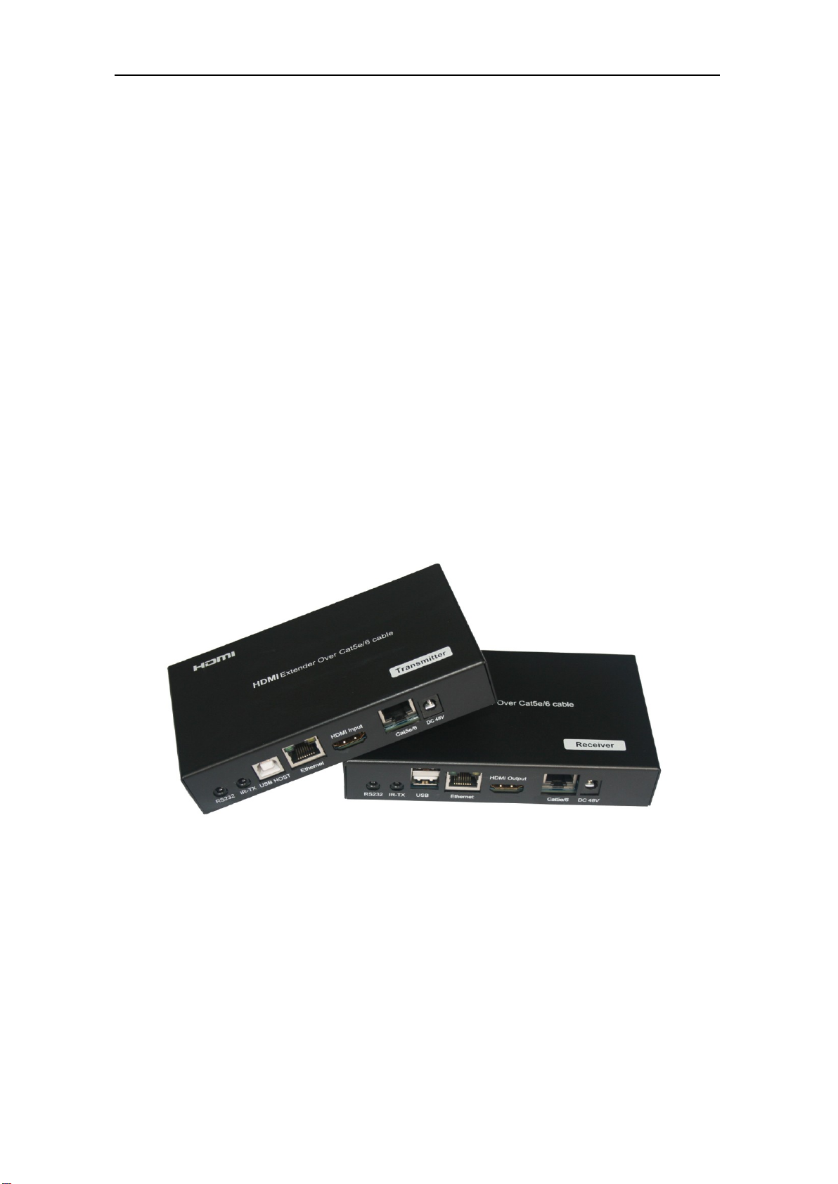
LM-EHU100 HDMI Extender
Operating Instruction

Operation instruction
2
Notice
The information in this document is subject to change without notice. Every effort has
been made in the preparation of this document to ensure accuracy of the contents, but all
statements, information, and recommendations in this document do not constitute the
warranty of any kind, express or implied.
Features
1)Extends HDMI with multi-channel digital audio, IR and RS232 up to 330 feet (100
meters)
2)Supports resolutions up to Ultra HD 4K x 2K (3840 x 2160 @ 30 Hz) and 1080P Full HD
3)5PlayTM convergence: uncompressed high definition Video and Audio, LAN serving,
Power over Ethernet and USB/RS-232/IR controls
4)Supports LPCM 7.1 audio, Dolby® TrueHD, Dolby Digital® Plus, and DTS-HD®
Master Audio™ pass-through
5)Supports 48bit Deep Color
6)Supports Bi-directional IR control.
7)CEC pass-through
8)Supports HDCP
Package Contents
1) 1xHDBaseT Transmitter
2) 1xHDBaseT Receiver
3) 2xIR-TX cable (no need IR-RX cable)
4) 1x48V/1.25A DC Adaptor
5) 1xUser Manual
6) 1xRS232/Female to 3.5 mm audio jack adapter
7) 1xRS232/Male to 3.5 mm audio jack adapter
8) 1x Pair wall/rack mounts

Operation instruction
3
Specifications
Operating Temperature Range
-5 to +35℃(+23 to +95℉)
Operating Humidity Range
5 to 90%RH (No Condensation)
Output Video Bandwidth
300MHz/10.2Gbps
Ethernet Speed
100 Mbps
Transmitter ports
1xHDMI (female)-Video Input
3x3.5mm Phone Jack (RS232 debug,RS232 and IR
Emitter Port) ,
1xUSB Host(Type B female)
1xLink Connector RJ-45
1xEthernet Port RJ-45
1xDC jack(DC48V)
Receiver Ports
1xHDMI (female)-Video output
3x3.5mm Phone Jack (RS232 debug,RS232 and IR
Emitter Port) ,
1xDouble USB (Type A female)
1xLink Connector RJ-45
1xEthernet Port RJ-45
1xDC jack(DC48V)
IR wavelength & frequency
Wavelength: 940nm IR Frequency: 38KHz
Resolution outputs
up to 4K x 2K (3840 x 2160 @ 24Hz)
Dimensions
Transmitter:5.5”Wx3”Hx.96”D(140x77.5x24.5mm)
Receiver:5.59”W x 3”Hx.96”D(142x77.5x24.5mm)
Power consumption
Transmitter: 10 W(MAX);Receiver: 10W(MAX)
Transmission Distance
330ft(100m)over Cat-5e(or better) cable
Net Weight
Transmitter: 339 g Receiver:343g
Operation instruction
4
Panel Description
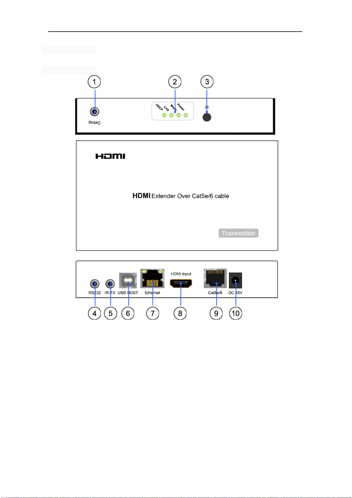
Transmitter Panel
1) Debug port: for firmware update(See default set for update)
2) LED Indicators:
A. Power–The PWR LED indicates that power is available to the unit.
B. Mode–The FW LED indicates that firmware has been loaded and the system is
running.
C. Link–The LINK LED indicates that an HDBaseT link connection has been
established between the two boards over the Cat5e cable.
D. HDCP
a. When the HDCP LED is on, it indicates that video content with HDCP protection is
being transferred.
b. When the HDCP LED is blinking, it indicates that video content without HDCP
protection is being transferred.
c. When the HDCP LED is off, it indicates that no video is being transferred.

Operation instruction
5
3) IR Receiver Window
4) RS232 –This connector is used to deliver RS232 traffic (up to 115200 bps) over the
HDBaseT link
5) IR-TX port - This jack can be used for connecting TX blaster cables.
6) USB HOST (B type) -This USB port on the transmitter board connects to the USB
HOST (i.e., PC or laptop).
7) Ethernet port–There is one standard Ethernet port
8) HDMI Input port
9) HDBaseT port-This is the Cat5e cable connection between the two units.
10) DC input port- The 48V DC is the power input for the transmitter
if power adapter connects with the transmitter, the transmitter is a PSD, the receiver is a PD.
if power adapter connects with the receiver, the receiver is a PSD, the transmitter is a PD).
Note: To avoid the unit being damaged, DO NOT connect power supply for both of
transmitter and receiver.
Update instruction:
①The user should receive a Firmware burn package, containing all software needed for
burning and updating the Firmware on the EEPROM.
②Connect debug port use RS232 cable from RS232 port of unit to PC.
③Power the unit.
④Extract the zipped file from the burn package to a directory (e.g. C:\dir_name).
⑤Browse to the directory (e.g. C:\dir_name\) and double click the batch file Update Source.
bat(for Transmitter) or Update Sink. Bat (for receiver).
⑥A short description of the link created between the PC and the board appears on the screen,
followed by the burn progress percentage report.
⑦A second stage of verifying the content of the EEPROM follows, also with a progress
percentage report
Operation instruction
6
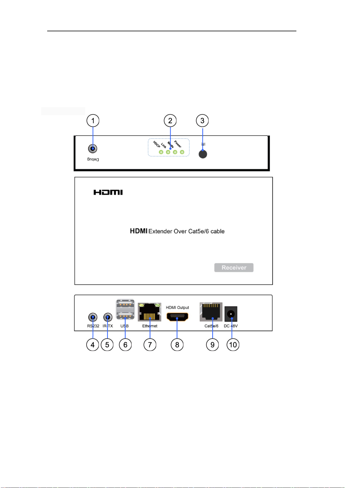
Receiver Panel
1) Debug port: for firmware update.(See default set for update)
2) LED Indicators:
A. Power–The PWR LED indicates that power is available to the unit.
B. Mode–The FW LED indicates that firmware has been loaded and the system is
running.
C. Link–The LINK LED indicates that an HDBaseT link connection has been established
between the two boards over the Cat5e cable.
D. HDCP
a. When the HDCP LED is on, it indicates that video content with HDCP protection is
being transferred.
Operation instruction
7
b. When the HDCP LED is blinking, it indicates that video content without HDCP
protection is being transferred.
c. When the HDCP LED is off, it indicates that no video is being transferred.
3) IR Receiver Window.
4) RS232 –This connector is used to deliver RS232 traffic (up to 115200 bps) over the
HDBaseT link.
5) IR-TX port - This jack can be used for connecting Tx blaster cables.
6) Double USB ports (type A) - This USB port on the sink board connects to the USB
devices or salave (i.e., mouse, keyboard).
7) Ethernet port–There is one standard Ethernet port.
8) HDMI Input port
9) HDBaseT port- Connect a Cat5e /6 cable between transmitter and receiver.
10) DC input port- The 48V DC is the power input for the receiver
if power adapter connects with the transmitter, the transmitter is a PSD, the receiver is a PD.
if power adapter connects with the receiver, the receiver is a PSD, the transmitter is a PD).
To avoid the unit being damaged, DO NOT connect power supply for both of
transmitter and receiver.
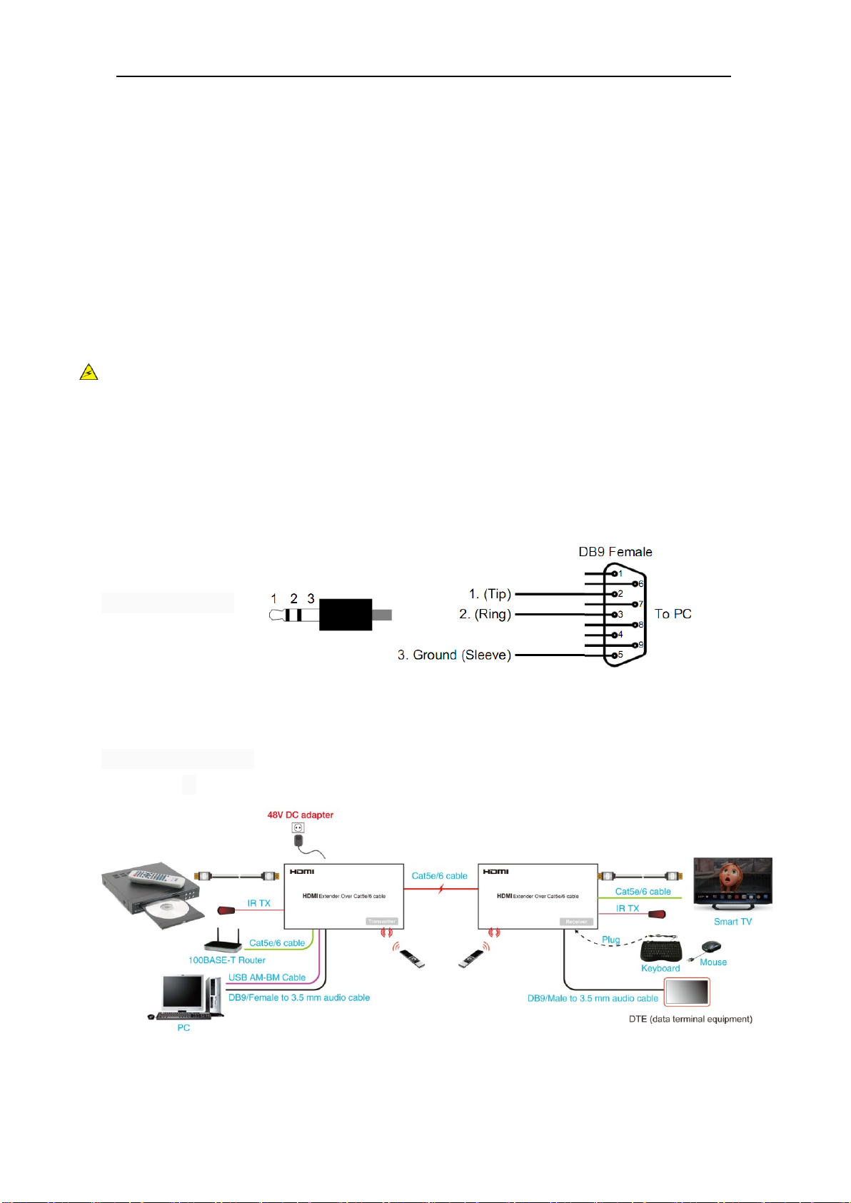
RS232 control:
illustrates the schematics of the RS232 connector used for the RS232 channel or for the
UART debug connector.
TO debug ports
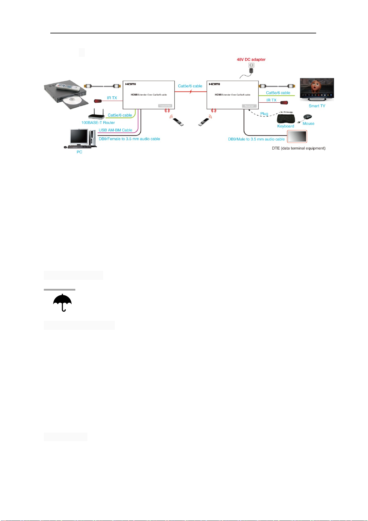
Connection Diagram
Application-1
Operation instruction
8
Application-2
CONNECTING AND OPERATING
1) Connect the HDMI signal sources (Such as DVD, STB etc) to HDMI Transmitter.
2) Connect cat5e/6 cables to both HDBaseT port of the transmitter and HDBaseT port of the
Receiver.
3) Connect the HDMI output (Such as HD-LCD, HD-DLP) into the Receiver.
4) Connect the IR-TX cables into transmitter IR-TX portS on the back panel and affix the
emitter onto the source IR windows ,Connect the IR-TX cables into receiver IR-TX portS on
the back panel and affix the emitter onto the sink IR windows.
5) Connect the 48V DC power supply into transmitter power port or receiver power port. (DO
NOT connect 48V DC power supply for both of transmitter and receiver )
Attention: Insert/Extract cables gently.
Safety information
safeguards
To reduce the risk of electric shock, do not expose this product to rain or moisture
PRODUCT SERVICE
1) Damage requiring service: The unit should be serviced by qualified service personnel if:
(a)The DC power supply cord or AC adaptor has been damaged;
(b)Objects or liquids have gotten into the unit;
(c)The unit has been exposed to rain;
(d)The unit does not operate normally or exhibits a marked change in performance;
(e)The unit has been dropped or the cabinet damaged.
2) Servicing Personnel: Do not attempt to service the unit beyond that described in these
operating instructions. Refer all other servicing to authorized servicing personnel.
3) Replacement parts: When parts need replacing ensure the servicer uses parts specified by
the manufacturer or parts that have the same characteristics as the original parts. Unauthorized
substitutes may result in fire, electric shock, or other hazards.
4) Safety check: After repairs or service, ask the servicer to perform safety checks to confirm
that the unit is in proper working condition.
WARRANTY
If your product does not work properly because of a defect in materials or workmanship, our
Company (referred to as "the warrantor" ) will , for the length of the period indicated as below,
(Parts(1)Year ,Labor(90) Days) which starts with the date of original purchase ("Limited

Operation instruction
9
Warranty period"), at its option either(a) repair your product with new or refurbished parts, or
(b) replace it with a new of a refurbished product. The decision to repair or replace will be
made by the warrantor.
During the "Labor" Limited Warranty period there will be no charge for labor.
During the "Parts" warranty period, there will be no charge for parts. You must mail-in your
product during the warranty period. This Limited Warranty is extended only to the original
purchaser and only covers product purchased as new. A purchase receipt or other proof of
original purchase date is required for Limited Warranty service.
Mail-In Service
When shipping the unit carefully pack and send it prepaid, adequately insured and preferably
in the original carton. Include a letter detailing the complaint and provide a day time phone
and/or email address where you can be reached.
LIMITED WARRANTY LIMITS AND EXCLUSIONS
1) This Limited Warranty ONLY COVERS failures due to defects in materials or
workmanship, and DOES NOT COVER normal wear and tear or cosmetic damage. The
Limited Warranty ALSO DOES NOT COVER damages which occurred in shipment, or
failures which are caused by products not supplied by warrantor,or failures which result from
accidents,misuse,abuse,neglect, mishandling, misapplication, alteration, faulty installation,
set-up adjustments, misadjustment of consumer controls, improper maintenance, power line
surge, lightning damage, modification, or service by anyone other than a Factory Service
center or other Authorized Servicer, or damage that is attributable to acts of God.
2) THERE ARE NO EXPRESS WARRANTIES EXCEPT AS LISTED UNDER "LIMITED
WARRANTY COVERAGE".THE WARRANTOR IS NOT LIABLE FOR INCIDENTAL OR
CONSEQUENTIAL DAMAGES RESULTING FROM THE USE OF THIS PRODUCT, OR
ARISING OUT OF ANY BREACH OF THIS WARRNTY. (As examples, this excludes
damages for lost time, cost of having someone remove or re-install an installed unit if
applicable, travel to and from the service, loss of or damage to media or images, data or other
recorded content. The items listed are not exclusive, but are for illustration only.)
3) PARTS AND SERVICE, WHICH ARE NOT COVERED BY THIS LIMITED
WARRANTY, ARE YOUR RESPONSIBILITY.
Table of contents
Other Shenzhen Shunxun Electronics Extender manuals


Popular Extender manuals by other brands

MuxLab
MuxLab VideoEase 500090 installation guide

Batavia
Batavia BT-EXP001 operating instructions

Ocean Matrix
Ocean Matrix OMX-01HMBL0001 INSTALLATION & SPECIFICATIONS

LINK-MI
LINK-MI LM-EW53 Operation manual

Savant
Savant HCX-4KHDR40 Quick reference guide

Extron electronics
Extron electronics HDMI 230 D Setup guide


