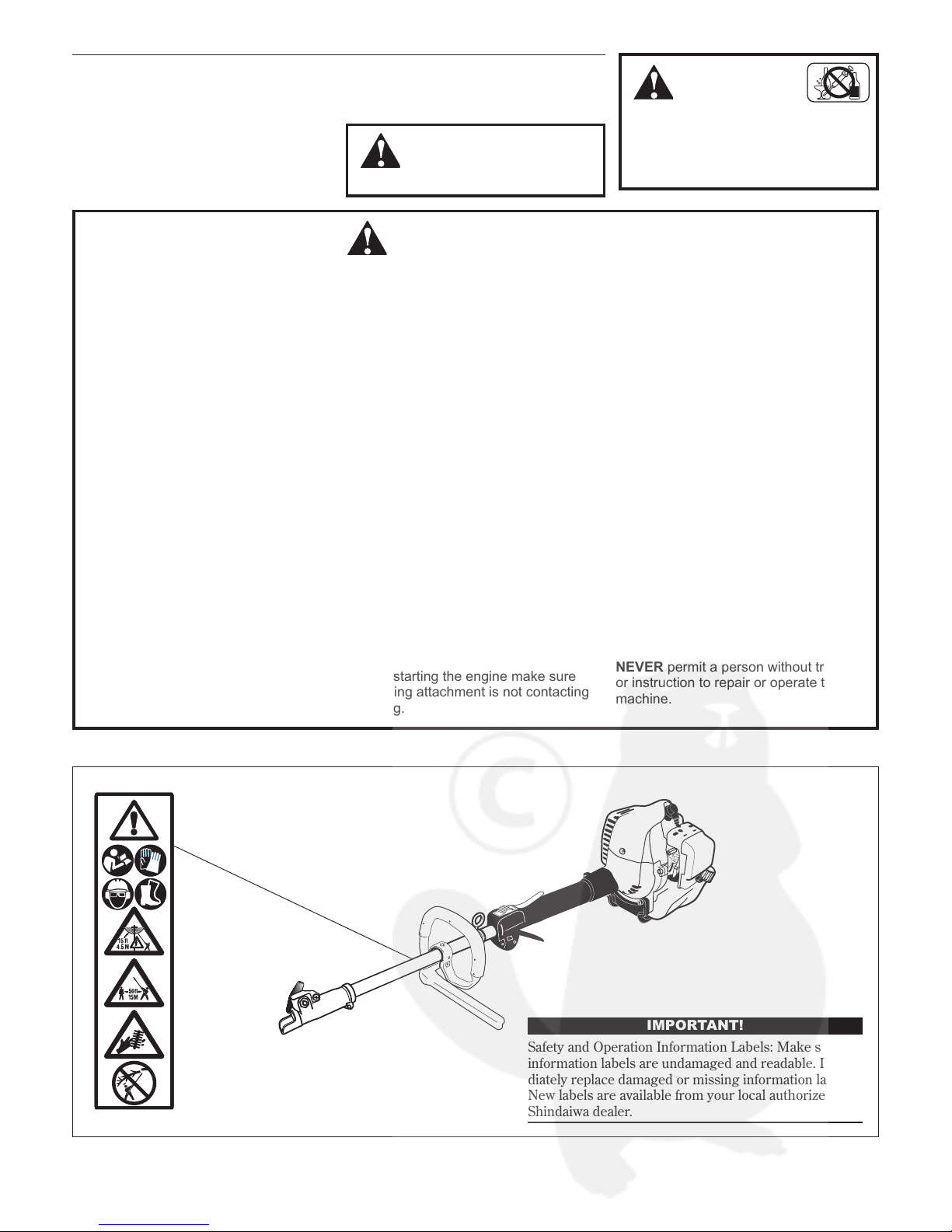
Shindaiwa M242S Owner's manual

M242
English .............. 1
Français ...... FR_1
Italiano ......... IT_1
SHINDAIWA OWNER’S/OPERATOR’S MANUAL
M242S MULTIPURPOSE
TOOL CARRIER
Part Number 65041-94310 Rev 03/2009
WARNING!
Read this manual and the manuals provided with the Shindaiwa
Splitboom Attachment series and familiarize yourself with its contents.
Minimize the risk of injury to yourself and others.
Always wear eye and hearing protection when operating this machine.
Do not operate or service this machine unless you clearly understand
this manual.
This machine is designed for cutting grass, weeds, and brush. Use
only for designated purpose.
Keep this manual available at all times so that you can reference it
whenever you have a question about the use of this unit.

2
Introduction
The Shindaiwa 242 series of hand-held
power equipment is designed and built
to deliver superior performance and
reliability without compromise to quality,
comfort, safety or durability.
Shindaiwa engines represent the leading
edge of high-performance engine
technology, delivering exceptionally high
power with remarkably low displacement
and weight. As an owner/operator, you’ll
soon discover for yourself why Shindaiwa
is simply in a class by itself!
Throughout this manual are special “atten-
tion statements”.
Attention Statements
WARNING!
A statement preceded by the
triangular attention symbol and the
word “WARNING” contains information
that should be acted upon to prevent
serious bodily injury.
CAUTION!
A statement preceded by the word
“CAUTION” contains information
that should be acted upon to prevent
mechanical damage.
IMPORTANT!
A statement preceded by the word
“IMPORTANT” is one that possesses spe-
cial significance.
NOTE:
A statement preceded by the word “NOTE”
contains information that is handy to know
and may make your job easier.
DANGER!
A statement preceded by the
triangular attention symbol and the
word “DANGER” contains information
that should be acted upon to prevent
serious injury or death.
IMPORTANT!
The operational procedures described in this manual are intended to help you get the most from this unit as well as to protect you and
others from harm. These procedures are guidelines for safe operation under most conditions, and are not intended to replace any safety
rules and/or laws that may be in force in your area. If you have questions regarding your Shindaiwa hand held power equipment, or if
you do not understand something in this manual, contact Shindaiwa Inc. at the address printed on the back of this Manual.
Shindaiwa Inc. reserves the right to make
changes to products without prior notice,
and without obligation to make alterations
to units previously manufactured.
IMPORTANT!
The information contained in these instruc-
tions describes units available at the time
of publication.
Operational and warning labels
Contents PAGE PAGEPAGE
WARNING!
The engine exhaust from this
product contains chemicals known to
to cause cancer, birth defects or other
reproductive harm.
Be aware of the danger of falling
debris.
Read and follow this manual, make
sure anyone using the trimmer does
likewise. Failure to do so could
result in serious personal injury or
machine failure. Keep this manual
for future reference.
Attachments for this unit operate
at very high speeds and can do
serious damage or injury if they are
misused or abused. Never allow a
person without training or instruction
to operate this unit!
Always wear a hard hat to reduce
the risk of head injuries during
operation of this machine. In addi-
tion, always wear eye and hearing
protection. Shindaiwa recommends
wearing a face shield as additional
face and eye protection.
Wear heavy duty, non-slip gloves.
Safety tip shoes or boots with non-
slip sole should be worn.
This product conducts electricity.
Keep the product and/or operator
a minimum distance of 15 feet
(4.5 meters) away from electrical
sources and power lines.
Keep bystanders at least 50 feet (15
meters) away from the operating
trimmer to reduce the risk of being
struck by falling objects or thrown
debris.
The blades / cutting attachments
are SHARP! Handle with care.
Safety ........................................................... 3
Product Description...................................4
Specifications..............................................5
Assembly and adjustments .......................6
Mixing fuel..................................................8
Filling the fuel tank....................................8
Starting the Engine ...................................9
Stopping the Engine ................................10
Adjusting Engine Idle ..............................10
Checking Unit Condition.........................10
Operation ..................................................11
Maintenance .............................................12
Long Term Storage..................................14
Troubleshooting Guide ...........................15
Declaration of Conformity.......................18
Sound Power Level (measured in
accordance with 2000/14/EC)

3
IMPORTANT!
Safety and Operation Information Labels: Make sure all
information labels are undamaged and readable. Imme-
diately replace damaged or missing information labels.
New labels are available from your local authorized
Shindaiwa dealer.
ALWAYS wear eye protection to shield
against thrown objects.
ALWAYS wear hearing protection devices
when operating this unit. Prolonged expo-
sure to excessive noise is fatiguing and
could lead to impaired hearing. The use
of proper ear protection can reduce this
potential hazard
NEVER operate the engine when transport-
ing the unit. Make sure cutter safety guards
are in place when transporting this unit.
NEVER operate the engine indoors!
Make sure there is always good ventila-
tion. Fumes from engine exhaust can
cause serious injury or death.
ALWAYS make sure there are no miss-
ing or loose fasteners and that the stop
switch and throttle controls are working
properly.
ALWAYS use the proper cutting tool for
the job.
ALWAYS clear your work area of trash or
hidden debris that could be thrown back
at you or toward a bystander.
ALWAYS make sure the cutting attach-
ment tool is properly installed and firmly
tightened before operation.
NEVER use a cracked or warped cutting
attachment: replace it with a serviceable
one and make sure it fits properly.
ALWAYS stop the engine immediately
if it suddenly begins to vibrate or shake.
Inspect for broken, missing or improperly
installed parts or attachments.
ALWAYS keep the unit as clean as prac-
tical. Keep it free of loose vegetation,
mud, etc.
NEVER extend trimming line beyond the
length specified for your unit.
ALWAYS hold the unit firmly with both
hands when cutting or trimming, and
maintain control at all times.
ALWAYS keep the handles clean.
ALWAYS disconnect the spark plug wire
before performing any maintenance work.
Before starting the engine make sure
the cutting attachment is not contacting
anything.
ALWAYS stop the engine immediately
and check for damage if you strike a
foreign object or if the unit becomes tan-
gled. Do not operate with broken or dam-
aged equipment.
ALWAYS maintain the Multipurpose
Engine according to this owner’s manual
and follow the recommended scheduled
maintenance.
NEVER allow the engine to run at high
RPM without a load. Doing so could
damage the engine.
ALWAYS use genuine Shindaiwa parts
and accessories when repairing or main-
taining this unit.
NEVER modify or disable any of the
unit’s devices. Use only Shindaiwa genu-
ine parts for repairs and maintenance.
WHEN transporting the unit in a vehicle,
tie it down securely to prevent damage
and fuel spillage.
NEVER permit a person without training
or instruction to repair or operate this
machine.
Work Safely
Attachments for this unit operate at very
high speeds and can do serious damage or
injury if they are misused or abused. Never
allow a person without training or instruc-
tion to operate this unit!
Stay Alert
You must be physically and mentally fit to
operate this unit safely.
Safety
WARNING!
Never make unauthorized
attachment installations.
WARNING!
Never operate power
equipment of any kind if you
are tired or if you are under the influ-
ence of alcohol, drugs, medication or
any other substance that could affect
your ability or judgement.
WARNING!
Use Good Judgment
Safety Labels

Product Description
M242 Multipurpose Tool Carrier
Outer Tube
Grip
Handle
Throttle Trigger
Hangar
Barrier bar
Throttle
Interlock
Ignition Switch
Strap
Coupler Screw Knob
Latch
Latch protector
Coupler
Spark Plug
Air cleaner
Fuel tank
Tank guard
Using the accompanying illustration as a
guide, familiarize yourself with this unit and
its various components. Understanding your
unit helps ensure top performance, long
service life and safer operation.
4

Specifications are subject to change without notice. *Shindaiwa One engine oil meets or exceeds these specifications and is recommended for all Shindaiwa products.
Speci cations
Engine Name M242/EC2
Engine model SF242EC2
Engine type 2-cycle catalyst
Dry weight (less attachments) 4.5 kg
Dimensions (L xHxW) 1038 mm x 213 mm x 250 mm
Displacement 23.9 cc
Bore x stroke 34 x 27 mm
Engine Speed at Maximum Power Output min-1
Maximum power output 0.8 kW @ 8000 min-1 (rpm)
Engine speed at idling min-1
Maximum engine speed min-1
Fuel tank capacity 620 cm3
Fuel/oil ratio 50:1 with ISO-L-EGD or JASO FC class 2-cycle mixing oil*
Carburetor Walbro WYK diaphragm-type
Ignition One-piece electronic transistor-controlled
Spark plug NGK BPMR6A
Spark plug torque value 17–19 N·m
Air filter Non-reversible foam filter element
Starting method Recoil
Stopping method Slide switch
Cooling system Forced air
Transmission type
Automatic, centrifugal clutch with bevel gear
Specifications are subject to change without notice.
*Sound Pressure Level: In accordance with EN ISO 11806 and ISO
22868 (average data between Idling and a WOT)
**Sound Power Level: In accordance with EN ISO 11806 and ISO
22868 (average data between at Idling and at WOT)
***Vibration Level: In accordance with EN ISO 11806 and ISO
22867.
Note 1: 8-tooth blade equipped
Note 2: Trimmer head equipped
Sound Pressure Level * (average data between at Idling and at WOT) Note 1 dB (A)
Sound Power Level ** (average data between at Idling and at WOT) Note 1 dB (A)
Vibration Level** (Idling [Front/Rear]) Note 1 / m/s2
(WOT [Front/Rear]) / m/s2
Sound Pressure Level * (average data between at Idling and at WOT) Note 2 dB (A)
Sound Power Level ** (average data between at Idling and at WOT) Note 2 dB (A)
Vibration Level*** (Idling [Front/Rear]) Note 2 / m/s2
(WOT [Front/Rear]) Note 2 / m/s2
With Shindaiwa SBA-TX24 Splitboom Attachment
Specifications are subject to change without notice.
*Sound Pressure Level: In accordance with ISO 11680-1
**Sound Power Level: In accordance with ISO 11680-1
***Vibration Level: In accordance with ISO11680-1
Sound Pressure Level * (Idling) dB (A)
(WOT) dB (A)
Sound Power Level ** (Idling) dB (A)
(WOT) dB (A)
Vibration Level*** (Idling [Front/Rear]) / m/s2
(WOT [Front/Rear]) / m/s2
With Shindaiwa SBA-P24 Splitboom Attachment (254 mm Guide Bar Equipped)
Specifications are subject to change without notice.
*Sound Pressure Level: In accordance with ISO 11680-1
**Sound Power Level: In accordance with ISO 11680-1
***Vibration Level: In accordance with ISO11680-1
Sound Pressure Level * (Idling) dB (A)
(WOT) dB (A)
Sound Power Level ** (Idling) dB (A)
(WOT) dB (A)
Vibrati Level*** (Idling [Front/Rear]) / m/s2
(WOT [Front/Rear]) / m/s2
With Shindaiwa SBA-AH2422 Splitboom Attachment
5

6
Assembly and adjustments
Prior to assembly
This Shindaiwa Multipurpose Tool Carrier
comes fully assembled. You only need
attach the accessory tool of your choice to
the powerhead.
Your Multipurpose tool carrier includes:
Shoulder strap
IMPORTANT!
The terms “left”, “left-hand”, and “LH”;
“right”, “right-hand”, and “RH”; “front” and
“rear” refer to directions as viewed by the
operator during normal operation.
WARNING!
Do not make unauthorized
modifications or alterations to any of
these units or their components.
When the two tube halves are locked together, press down on the spring-loaded latch protector
Press latch
With the unit on a clean, flat surface,1.
loosen the coupler screw. The spring-
loaded coupler protector should pop up.
Press down on the latch with your finger2.
or thumb. This releases the coupler lock.
Pull the upper tube assembly out of the3.
coupler.
Disassembling the tube sections
Tool assembly
Lower tube assembly
Coupler
Latch
Coupler screw
knob
Locking hole
Latch protector (extended)
Slip off the protective plastic cover(s)2.
from the ends of the tube(s), and
loosen the coupler screw knob.
Insert the tool assembly into the cou-3.
pler, with the tool decal facing up, until
the line of the decal is flush with the
end of the coupler.
Twist the tool assembly back and forth4.
until you are sure it snaps in place by
the coupler latch.
When the two tube halves are locked5.
together, press down on the spring-
loaded latch protector and tighten the
coupler screw knob.
Latch Protector (lowered)
Coupler Screw Knob
Coupler
Assembling tube sections
Place powerhead/lower tube assembly1.
on a clean, flat surface so that both
assemblies fit end to end. The power-
head/lower tube assembly should be
facing positioned with the locking hole
in the tube end facing up.
CAUTION!
Keep the open ends of the tubes clean
and free of debris!
Insert the tool assembly into the coupler
Press down on the latch with your finger or thumb
Kit containing this owner’s/operator’s
manual and tool kit for routine mainte-
nance. Tool kits vary by model and may
include a hex wrench, and a spark plug/
screwdriver combination wrench.
CAUTION!
Verify that there is no gap between the
latch protector and coupler.

4 - 6 mm
Remove air cleaner cover
Throttle lever free play
Lock Nut
Cable
Adjuster
Adjust as required to obtain 4-6 mm free play
7
Assembly and adjustments (continued)
Throttle lever free play
The thro
ttle lever free play should be
approximately 4 - 6 mm. Make sure that
the throttle lever operates smoothly
without binding. If it becomes necessary to
adjust the lever free play, follow the proce-
dures and illustrations that follow.
Loosen the air cleaner cover knobs and1.
remove the air cleaner cover.
Loosen the lock nut on the cable2.
adjuster.
Turn the cable adjuster in or out as3.
required to obtain proper free play 4-6
mm (3/16-1/4 inch).
Tighten the locknut.4.
Reinstall the air cleaner cover.5.
Adjusting the handle
Use both hands to position handle
assembly in best location for operator
comfort.
Handle arrow
points toward
coupler.
Loosen square nut in handle
Your Shindaiwa Multi-Purpose Tool Car-
rier comes with the handle installed. It can
be re-adjusted for operator comfort in the
following manner.
Place the unit on a clean, flat surface.1.
With a hex wrench, loosen the square2.
nut as shown.
Slide handle assembly to desired3.
position.
NOTE
Moving the handle may require two hands
and rocking motions, as the handle and
clamp fit tightly to the outer tube.

8
CAUTION
Never use any type of gasoline contain-
ing more than 10% alcohol by volume!
Some types of gasoline contain alcohol
as an oxygenate. Oxygenated gaso-
line may cause increased operating
temperatures. Under certain condi-
tions, alcohol-based gasoline may also
reduce the lubricating qualities of some
2-cycle mixing oils.
Generic oils and some outboard
oils may not be intended for use in
high-performance 2-cycle engines,
and should never be used in your
Shindaiwa engine.
Mixing fuel
Filling the fuel tank
CAUTION
This engine is designed to operate on
a 50:1 mixture consisting of unleaded
gasoline and ISO-L-EGD or JASO FD
class 2-cycle mixing oil only. Use of
non-approved mixing oils can lead to
excessive carbon deposits.
Use only fresh, clean unleaded gasoline
with a pump octane of 87 or higher.
Mix all fuel with a 2-cycle air-cooled
mixing oil that meets or exceeds ISO-L-
EGD and/or JASO FD classified oils at
50:1 gasoline/oil ratio.
Examples of 50:1 mixing quantities
WARNING!
Minimize the Risk of Fire
Gasoline 2-cycle mixing oil
liters milliliters
2.5 - L
50 mL
5 - L 100 mL
10 - L 200 mL
20 - L 400 mL
IMPORTANT!
Mix only enough fuel for your immediate
needs! If fuel must be stored longer than 30
days and oil with fuel stabilizer is not
used, it should first be treated with a fuel
stabilizer such as STA-BIL™.
Oil is a registered JASO FD classi-
fied oil and also meets or exceeds ISO-L-EGD
performance requirements. Shindaiwa One is
recommended for use in all Shindaiwa low emis-
sions engines. Shindaiwa One also includes a
fuel stabilizer.
NEVER smoke or light fires near the
engine.
ALWAYS stop the engine and allow
it to cool before refueling.
ALWAYS Wipe all spilled fuel and
move at least 3 meters (10 feet)
from the fueling point and source
before starting.
NEVER place flammable material
close to the engine muffler.
NEVER operate the engine with-
out the muffler and spark arrester
screen in place and in good work-
ing condition.
FUEL IS HIGHLY FLAMMABLE.
ALWAYS store gasoline in a con-
tainer approved for flammable
liquids.
ALWAYS inspect the unit for fuel
leaks before each use. During each
refill, check that no fuel leaks from
around the fuel cap and/or fuel tank.
If fuel leaks are evident, stop using
the unit immediately. Fuel leaks must
be repaired before using the unit.
ALWAYS move the unit at least 3
meters (10 feet) away from a fuel
storage area or other readily flam-
mable materials before starting
the engine.
Place the unit on a flat, level surface.1.
Clear any dirt or other debris from2.
around the fuel filler cap.
Remove the fuel cap, and fill the tank3.
with clean, fresh fuel.
Reinstall the fuel filler cap and tighten4.
firmly.
Wipe away any spilled fuel before start-5.
ing engine.
CAUTION!
Slowly remove the fuel cap only after
stopping the engine
CAUTION!
Mix and pour fuel outdoors where there
are no sparks and flames.

Make sure the
attachment is clear
of obstructions!
...and pull recoil
starter handle
upward
Hold the unit
rmly...
After engine starts, move
choke to OPEN position
Open
Closed
Move the choke lever to the
CLOSED position
Slide ignition to ON
Primer Bulb
Return Tube
ON
Press primer bulb...
9
Starting the Engine
IMPORTANT!
Engine ignition is controlled by a two position switch mounted on the throttle housing labeled, “I” for ON or START and “O” for OFF or STOP.
Slide the ignition switch to the “I”1.
position.
Press the primer bulb until fuel can2.
be seen flowing in the transparent
return tube.
Set the choke lever to the CLOSED3.
position if engine is cold.
While holding the outer tube firmly4.
with left hand. Use your other hand
to slowly pull the recoil starter handle
until resistance is felt, then pull quickly
to start the engine.
WARNING!
Never start the engine from
the operating position.
When the engine starts, slowly move5.
the choke lever to the “OPEN” position.
If the engine stops after the initial start,
close the choke and restart.
IMPORTANT!
The primer system only pushes fuel
through the carburetor. Repeatedly press-
ing the primer bulb will not flood the
engine with fuel.
CAUTION!
Do not pull the recoil starter to the end
of the rope travel. Pulling the recoil
starter to the end of the rope travel can
damage the starter.
WARNING!
The cutting attachment may
rotate when the engine is started!
IMPORTANT!
If the engine fails to start after several
attempts with the choke in the closed
position, the engine may be flooded with
fuel. If flooding is suspected, see the sec-
tion “Starting a Flooded Engine” for more
information
After the engine starts, allow the engine
to warm up at idle for 2 or 3 minutes
before operating the machine.
Advancing the throttle makes the cut-
ting attachment rotate faster; releasing
the throttle makes the attachment stop
running. If the cutting attachment con-
tinues to rotate refer to “Engine Idle
Adjustment” for engine idle adjust-
ment procedures.
When the engine starts
After the engine is warm, pick up the
unit and clip on the strap or harness if
so equipped. See the section “Opera-
tion: Shoulder Strap” for instructions.
Starting a warm engine involves all of the
steps of starting a cold engine, EXCEPT:
Starting a warm engine
Do not press the primer bulb.
The choke should be in the OPEN ( )
position.
If the engine does not start, follow the cold
engine starting procedure.
WARNING!
Keep all parts of your body
away from the rotating cutting attach-
ment and hot surfaces.
WARNING!
Never start the engine without
the tool assembly and cutting attach-
ments installed to the engine. Failure
to do so could damage the engine and
increase unexpected risk to the opera-
tor and any bystander.

Slide ignition to OFF
OFF
IMPORTANT
When the unit is turned off make sure the
cutting attachment has stopped before the
unit is set down.
10
Idle the engine briefly before stopping
(about 2 minutes), then slide the ignition
switch to the “O” (Engine OFF) position.
Stopping the Engine
Adjusting Engine Idle
Idle Adjusting
Screw
The engine must return to idle speed
whenever the throttle lever is released.
Idle speed is adjustable, and must be set
low enough to permit the engine clutch to
disengage the cutting attachment.
Idle Speed Adjustment
WARNING!
The cutting attachment must
NEVER rotate at engine idle! If the
idle speed cannot be adjusted by the
procedure described here, return the
trimmer to your Shindaiwa dealer for
inspection.
Place the unit on the ground, then start1.
the engine, and then allow it to idle 2-3
minutes until warm.
If the attachment rotates when the2.
engine is at idle, reduce the idle speed
by turning the idle adjustment screw
counter-clockwise.
If a tachometer is available, the engine3.
idle speed should be final adjusted
to the settings recommended in the
Specifications section.
NEVER operate the unit with the cutting
attachment shield or other protective
devices removed!
Use only authorized Shindaiwa parts and
accessories with your Shindaiwa trimmer.
Do not make modifications to this unit with-
out written approval from Shindaiwa, Inc.
ALWAYS make sure the cutting attach-
ment is properly installed and firmly
tightened before operation.
NEVER use a cracked or warped cutting
attachment: replace it with a serviceable
one.
Checking Unit Condition
The cutting attachment may be moving
during carburetor adjustments. Wear your
protective equipment and observe all
safety instructions.
ALWAYS make sure the cutting attach-
ment fits properly into the appropriate
attachment holder. If a properly installed
attachment vibrates, replace the attach-
ment with new one and re-check.
ALWAYS stop the engine immediately and
check for damage if you strike a foreign
object or if the unit becomes tangled.
Do not operate with broken or damaged
equipment.
NEVER allow the engine to run at high
RPM without a load. Doing so could dam-
age the engine.
NEVER operate a unit with worn or dam-
aged fasteners or attachment holders.
When transporting, make sure the engine
is not running and blades are covered with
blade covers.
WARNING!
A cutting attachment shield
or other protective device is no
guarantee of protection against rico-
chet. YOU MUST ALWAYS GUARD
AGAINST FLYING DEBRIS!
Slide the ignition switch button to the1.
STOP position.
Disconnect the spark plug wire, and2.
remove the spark plug.
If the spark plug electrodes and3.
ceramic insulator are fouled or soaked
with fuel, clean or replace the plug. For
spark plug specifications and gapping
procedure, refer to the “Maintenance”
section.
CAUTION!
Incorrect spark plug installation may
cause serious engine damage!
Starting a flooded engine
Open the choke.4.
Hold the throttle control lever5.
depressed and crank the engine several
times to clear excess fuel from the
combustion chamber.
Reinstall the spark plug finger tight and6.
tighten it firmly with the spark plug
wrench provided in the tool kit.
Adjusting engine idle
Starting the Engine (continued)
Repeat the warm engine starting7.
procedure.
If the engine fails to start, consult the8.
troubleshooting guide provided.
NOTE
Carburetor fuel mixture adjustments are
preset at factory and cannot be serviced
in the field.

11
Operation
NEVER operate the unit with the cutting
attachment shield or other protective
devices removed!
Use only authorized Shindaiwa parts and
accessories with your Shindaiwa trimmer.
Do not make modifications to this unit with-
out written approval from Shindaiwa, Inc.
ALWAYS make sure the cutting attach-
ment is properly installed and firmly
tightened before operation.
NEVER use a cracked or warped cutting
attachment: replace it with a serviceable one.
Checking Unit Condition
ALWAYS make sure the cutting attach-
ment fits properly into the appropriate
attachment holder. If a properly installed
attachment vibrates, replace the attachment
with new one and re-check.
ALWAYS stop the engine immediately
and check for damage if you strike a for-
eign object or if the unit becomes tangled.
Do not operate with broken or damaged
equipment.
NEVER allow the engine to run at high
RPM without a load. Doing so could dam-
age the engine.
NEVER operate a unit with worn or dam-
aged fasteners or attachment holders.
WARNING!
A cutting attachment shield or
other protective device is no guarantee
of protection against ricochet. YOU
MUST ALWAYS GUARD AGAINST
FLYING DEBRIS!
Hook the strap hook to the hanger on1.
the outer tube.
Wear the shoulder strap so that the2.
hook stays at your right hand side.
Adjust the length of the shoulder strap3.
so that you can hold and operate the
machine comfortably.
IMPORTANT!
Adjust the shoulder strap or harness so
the shoulder pad rests comfortably on the
off-side shoulder and the cutting path of
the cutting attachment is parallel to the
ground. Make sure all hooks and adjust-
ment devices are secure.
WARNING!
Always wear a shoulder strap
when operating this unit with a blade.
A shoulder strap is also recommened
when using trimmer line.
Shoulder Strap
NOTE:
Using a shoulder strap with a brushcutter
allows you to maintain proper control
of the unit and reduces fatigue during
extended operation.
Emergency Release
In case of emergency, strongly pull the
white tab at the hook. The machine will be
released from the strap.

12
Maintenance
WARNING!
Before performing any mainte-
nance, repair, or cleaning work on the
unit, make sure the engine and cutting
attachment are completely stopped.
Disconnect the spark plug wire before
performing service or maintenance.
WARNING!
Non-standard accessories,
cutting attachment, or replacement
parts may not operate properly with
your unit and may cause damage and
lead to personal injury.
Prior to each work day, perform the
following:
Remove all dirt and debris from the
engine, check the cooling fins and
air cleaner for clogging, and clean as
necessary.
Check the entire unit for leaking fuel or
grease.
Check for loose or missing screws or
components.
Daily maintenance
10-hour maintenance
Make sure nuts, bolts, and screws
(except carburetor idle speed adjusting
screws) are tight.
Carefully remove any accumulations of dirt
or debris from the muffler and fuel tank.
Check cooling air intake area at base of
crankcase. Remove all debris. Dirt build-up
in these areas can lead to engine overheat-
ing, fire, or premature wear.
IMPORTANT!
MAINTENANCE, REPLACEMENT
OR REPAIR OF EMISSION CONTROL
DEVICES AND SYSTEMS MAY BE PER-
FORMED BY ANY REPAIR ESTABLISH-
MENT OR INDIVIDUAL; HOWEVER,
WARRANTY REPAIRS MUST BE PER-
FORMED BY A DEALER OR SERVICE
CENTER AUTHORIZED BY SHINDAIWA
INC. THE USE OF PARTS THAT ARE NOT
EQUIVALENT IN PERFORMANCE AND
DURABILITY TO AUTHORIZED PARTS
MAY IMPAIR THE EFFECTIVENESS OF
THE EMISSION CONTROL SYSTEM AND
MAY HAVE A BEARING ON THE OUT-
COME OF A WARRANTY CLAIM.
Muffler
This unit must never be operated with a
faulty or missing spark arrester or muf-
fler. Make sure the muffler is well secured
and in good condition. A worn or damaged
muffler is a fire hazard and may also cause
hearing loss.
General maintenance
NOTE:
Using non-standard replacement parts
could invalidate your Shindaiwa warranty.
CAUTION!
Do not operate the unit if the air
cleaner or filter is damaged, or if the
filter is wet or water soaked.
Perform more frequently in dusty or
dirty conditions.
Remove the air cleaner filter. Clean or
replace as necessary. To clean filter wash
it thoroughly in soap and water. Let it dry
before reinstalling the filter.
Unscrew
Fastener
Remove and clean or
replace the element
Spark Plug
Keep the spark plug and wire connections
tight and clean.
Fasteners
Make sure nuts, bolts, and screws (except
carburetor adjusting screws) are tight.
Remove all dirt and debris from the engine,
cooling fins, and air intake area
Cooling ns Cooling
ns
Air
intake

Fuel lter element
Hooked wire
Fuel filter maintenance
Clean the spark plug
and check the gap at
the electrode.
0.6–0.7 mm
(0.024–0.028 inch)
13
Every 50 hours of operation; more
frequnetly in dusty conditions:
Remove and clean the cylinder cover
and clean dirt and debris from the cylin-
der cooling fins.
Remove and replace the fuel filter
element.
Use a hooked wire to extract the fuel filter
from inside the fuel tank. Inspect the fuel
filter element. If it shows signs of contami-
nation, replace with a genuine Shindaiwa
replacement fuel filter element.
50 hour maintenance
CAUTION!
Make sure you do not pierce the fuel
line with the end of the hooked wire.
The line is delicate and can be dam-
aged easily.
Every 10 to 15 hours of operation:
Remove and clean the spark plug. Adjust
the spark plug electrode gap to 0.6 - 0.7 mm
(0.024 - 0.028 inch). If the spark plug must
be replaced, use only the an NGK BPMR6A
or equivalent resistor type spark plug of the
correct heat range
CAUTION!
Before removing the spark plug, clean
the area around the plug to prevent
dirt and debris from getting into the
engine’s internal parts.
10/15 hour maintenance
Maintenance (continued)
NOTE
The NGK BPMR6A also meets the
requirements for electro magnetic compli-
ance (EMC).
Before reinstalling the new filter element,
inspect the condition of all the fuel system
components (fuel pick-up line, fuel return
line, tank vent line, tank vent, fuel cap
and fuel tank). If damage, splitting or
deterioration is noted, the unit should
be removed from service until it can be
inspected or repaired by a Shindaiwa-
trained service technician.

Engine Cover
Screws
Muffler Cover
Engine Cover
Muffler
Cover
Screw
Spark Arrester
Screen Spark Arrester
Cover
Outlet
Screws
Muffler Gasket
Muffler
Gasket
Muffler
Screws
Muffler and spark arrester maintenance
135 hour maintenance
14
Maintenance (continued)
Every 135 hours of operation, remove
and clean the muffler.
IMPORTANT!
If you note excessive carbon buildup, con-
sult with an authorized Shindaiwa servic-
ing dealer.
Remove the spark plug boot.1.
With a 4mm hex wrench remove the 12.
muffler cover and 3 engine cover screws
and the engine cover. The muffler cover
is attached to the engine cover at the
top and front by tabs. To remove push
inward at arrow area while pulling out-
ward. See insert image.
With a Phillips type screwdriver remove3.
the 5 screws holding the spark arrester
screen and cover to the muffler.
Remove the screen and clean it with a4.
stiff bristle brush.
If the engine becomes sluggish and low on
power, check and clean the spark arrester
screen.
WARNING!
Never operate the unit with a
damage or missing muffler or spark
arrester! Operating with a missing
or damaged spark arrester is a fire
hazard and could also damage your
hearing.
Remove the 3 muffler bolts and the5.
muffler.
Inspect the cylinder exhaust port for6.
any carbon buildup.
Gently tap the muffler on a wood sur-7.
face to dislodge any loose carbon.
Reassemble the spark arrester, muffler8.
and engine cover in the reverse order
of disassembly.
Whenever the unit will not be used for 30
days or longer, use the following proce-
dures to prepare it for storage:
Clean external parts thoroughly.
Drain all the fuel from the carburetor
and the fuel tank.
Long Term Storage
Remove remaining fuel from the fuel
lines and carburetor with the fuel
drained from the fuel tank. To do so:
Prime the primer bulb until no1.
more fuel is passing through.
Start and run the engine until it2.
stops running.
Repeat steps 1 and 2 until the3.
engine will no longer start.
Remove the spark plug and pour about
7.4 mL (1/4 oz.) of 2-cycle mixing oil
into the cylinder through the spark plug
hole. Slowly pull the recoil starter 2 or 3
times so oil will evenly coat the interior
of the engine. Reinstall the spark plug.
IMPORTANT!
All stored fuels should be stabilized with a
fuel stabilizer such as STA-BIL, if oil
with fuel stabilizer is not used.
CAUTION
Gasoline stored in the carburetor for
extended periods can cause hard start-
ing, and could also lead to increased
service and maintenance costs.
Before storing the unit, repair or
replace any worn or damaged parts.
Remove the air cleaner element from
the carburetor and clean it thoroughly
with soap and water, let dry and reas-
semble the element.
Store the unit in a clean, dust-free area.

NO
NO
NO
NO
NO
YES
YES
YES
YES
YES
15
Troubleshooting Guide
Does the engine crank?
Good compression?
Does the tank contain
fresh fuel of the proper
grade?
Is fuel visible and
moving in the return
line when priming?
Is there spark at the spark
plug wire terminal?
Check the spark plug.
The plug is damaged internally or of
the wrong size.
What To Check Possible Cause Remedy
Faulty recoil starter.
Fluid in the crankcase.
Internal damage.
Loose spark plug.
Excess wear on cylinder, piston,
rings.
Fuel incorrect, stale, or contaminated;
mixture incorrect.
Check for clogged fuel filter
and/or vent.
The ignition switch is in “O” (OFF)
position.
Shorted ignition ground.
Faulty ignition unit.
If the plug is wet, excess fuel may be
in the cylinder.
The plug is fouled or improperly
gapped.
Consult with an authorized
servicing dealer.
Tighten and re-test.
Consult with an authorized
servicing dealer.
Replace fuel filter or vent as required.
Restart.
Move switch to “I” (ON) position
and restart.
Consult with an authorized
servicing dealer.
Crank the engine with the plug
removed, reinstall the plug, and restart.
Clean and regap the plug to
0.6 mm - 0.7 mm (0.025 - 0.028 in.) Restart.
Replace the spark plug. Check the
“Specifications” section for the correct
plug for your unit. Restart.
Primer pump functioning
incorrectly.
Consult with an authorized
servicing dealer.
ENGINE DOES NOT START
Refill with fresh, clean unleaded gasoline
with a pump octane of 87 or higher mixed
with a 2-cycle mixing oil that meets or
exceeds ISO-L-EGD and/or JASO FD
classified oils at 50:1 gasoline/oil ratio.

16
Troubleshooting Guide (continued)
Operator is overworking the unit.
Carburetor mixture is too lean.
Improper fuel ratio.
Fan, fan cover, cylinder fins dirty or
damaged
Carbon deposits on the piston or in the
muffler.
Clogged air cleaner element.
Loose or damaged spark plug.
Air leakage or clogged fuel line.
Consult with an authorized
servicing dealer.
Clean, repair or replace as necessary.
Consult with an authorized servicing
dealer
Clean or replace the air filter
Tighten or replace the spark plug.
Restart. Check the Specifications page
in this manual for the correct spark
plug for this unit.
Repair or replace fuel filter and/or
fuel line.
Water in the fuel.
Piston seizure.
Faulty carburetor and/or diaphragm
Overheating condition.
Improper fuel.
Carbon deposits in the combustion
chamber.
Check fuel octane rating; check for
presence of alcohol in the fuel. Refuel
as necessary.
Consult with an authorized
servicing dealer.
Refill with fresh fuel/oil mixture.
Consult with an authorized
servicing dealer.
Consult with an authorized
servicing dealer.
Is the engine
overheating?
Engine is rough at all
speeds. May also have
black smoke and/or
unburned fuel at the
exhaust.
Engine is knocking.
What To Check Possible Cause Remedy
LOW POWER
Refill with fresh, clean unleaded gasoline with
a pump octane of 87 or higher mixed with a
2-cycle mixing oil that meets or exceeds ISO-
L-EGD and/or JASO FD classified oils at 50:1
gasoline/oil ratio.
Operate at slower rate.

17
ADDITIONAL PROBLEMS
Fuel tank empty.
Clogged fuel filter.
Water in the fuel.
Shorted spark plug or loose terminal.
Ignition failure.
Piston seizure.
Ground (stop) wire is disconnected or
switch is defective
Overheating due to incorrect spark plug
Clogged air filter.
Clogged fuel filter.
Lean fuel/air mixture.
Idle speed set too low.
Switch turned off.
Refuel. See Fuel section of manual.
Replace fuel filter.
Drain; replace with clean fuel. See Fuel
section of manual.
Clean or replace spark plug. Check
the Specifications page in this manual
for the proper spark plug for your unit.
Tighten the terminal.
Replace the ignition unit.
Consult with an authorized
servicing dealer
Test and replace as required.
Idle engine until cool. Replace the spark
plug. Check the Specifications page in this
manual for the proper spark plug for your
unit.
Clean or replace the air filter.
Replace the fuel filter.
Consult with an authorized
servicing dealer.
Reset the switch and re-start.
Overheated engine.
Engine idle too high.
Broken clutch spring or worn clutch
spring boss.
Loose attachment holder.
Poor acceleration.
Engine stops abruptly.
Engine difficult to shut
off.
Cutting attachment moves
at engine idle.
Attachment will not move.
Idle engine until cool.
Replace spring/shoes as required.
Inspect and re-tighten holders securely.
Shaft not installed in powerhead or
gearcase.
Broken shaft.
Damaged gearcase.
Inspect and reinstall as required.
Consult with a authorized
servicing dealer.
Troubleshooting Guide (continued)
What To Check Possible Cause Remedy
Warped or damaged attachment.
Loose gearcase.
Excessive vibration.
Inspect and replace attachment
as required.
Tighten gearcase securely.
Bent main shaft/worn or damaged
bushings.
Inspect and replace as necessary.
Engine will not idle down.
Engine idle is set too high.
Engine has air leak. Consult with a authorized
servicing dealer.
Adjust idle. Check Specifications page
for correct idle speed.
Adjust idle. Check Specifications page
for correct idle speed.
Adjust idle. Check Specifications page
for correct idle speed.

18
Declaration of Conformity
DECLARATION OF
CONFORMITY
We hereby declare the Shindaiwa Pole Pruner, Model SBA-P24 (SBA-P24/EU with M242/
EC2), meets the following respective requirements.
Council Directives: Standard taken:
2004/108/EC as amended ISO 12100 - 1&2
98/37/EC as amended ISO 11806
2000/14/EC as amended CISPR 12
2004/26/EC as amended
Measured sound power level: 107 dB(A)
Guaranteed sound power level: 108 dB(A)
Authorized representative in the European Community:
Mr. Phil Williams
Worldwide Corporate Advisors LLP
8-10 Hallam Street, Suite 405
London W1W 6JE
Tel: +44 20 3008 8910, Fax: +44 20 3008 8911
Technical documentation is kept by:
K. Maeda DIV. Manager
Engineering Research and Development DIV.
Shindaiwa Corporation
Head office: 6-2-11, Ozuka-Nishi, Asaminami-Ku,
Hiroshima, 731-3167, Japan
TEL: 81-82-849-2003, FAX: 81-82-849-2482
S. Torigoe
DIV. Manager
Quality Assurance DIV.
Shindaiwa Corporation
Head office: 6-2-11, Ozuka-Nishi, Asaminami-Ku,
Hiroshima, 731-3167, Japan
TEL: 81-82-849-2206, FAX: 81-82-849-2481
20 November, 2008

19
Declaration of Conformity
DECLARATION OF
CONFORMITY
We hereby declare the Shindaiwa Brushcutter, Model SBA-TX24 (SBA-TX24/EU with
M242/EC2), meets the following respective requirements
Council Directives: Standard taken:
2004/108/EC as amended ISO 12100 - 1&2
98/37/EC as amended ISO 11806
2000/14/EC as amended CISPR 12
2004/26/EC as amended
Measured sound power level: 107 dB(A)
Guaranteed sound power level: 108 dB(A)
Authorized representative in the European Community:
Mr. Phil Williams
Worldwide Corporate Advisors LLP
8-10 Hallam Street, Suite 405
London W1W 6JE
Tel: +44 20 3008 8910, Fax: +44 20 3008 8911
Technical documentation is kept by:
K. Maeda DIV. Manager
Engineering Research and Development DIV.
Shindaiwa Corporation
Head office: 6-2-11, Ozuka-Nishi, Asaminami-Ku,
Hiroshima, 731-3167, Japan
TEL: 81-82-849-2003, FAX: 81-82-849-2482
S. Torigoe
DIV. Manager
Quality Assurance DIV.
Shindaiwa Corporation
Head office: 6-2-11, Ozuka-Nishi, Asaminami-Ku,
Hiroshima, 731-3167, Japan
TEL: 81-82-849-2206, FAX: 81-82-849-2481
20 November, 2008

20
Declaration of Conformity
DECLARATION OF
CONFORMITY
We hereby declare the Shindaiwa Articulated Hedge trimmer, Model SBA-AH2422 (SBA-
AH2422/EU with M242/EC2), meets the following respective requirements
Council Directives: Standard taken:
2004/108/EC as amended ISO 12100 - 1&2
98/37/EC as amended ISO 11806
2000/14/EC as amended CISPR 12
2004/26/EC as amended
Measured sound power level: 107 dB(A)
Guaranteed sound power level: 108 dB(A)
Authorized representative in the European Community:
Mr. Phil Williams
Worldwide Corporate Advisors LLP
8-10 Hallam Street, Suite 405
London W1W 6JE
Tel: +44 20 3008 8910, Fax: +44 20 3008 8911
Technical documentation is kept by:
K. Maeda DIV. Manager
Engineering Research and Development DIV.
Shindaiwa Corporation
Head office: 6-2-11, Ozuka-Nishi, Asaminami-Ku,
Hiroshima, 731-3167, Japan
TEL: 81-82-849-2003, FAX: 81-82-849-2482
S. Torigoe
DIV. Manager
Quality Assurance DIV.
Shindaiwa Corporation
Head office: 6-2-11, Ozuka-Nishi, Asaminami-Ku,
Hiroshima, 731-3167, Japan
TEL: 81-82-849-2206, FAX: 81-82-849-2481
20 November, 2008
Table of contents
Other Shindaiwa Tools manuals