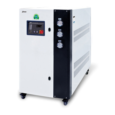
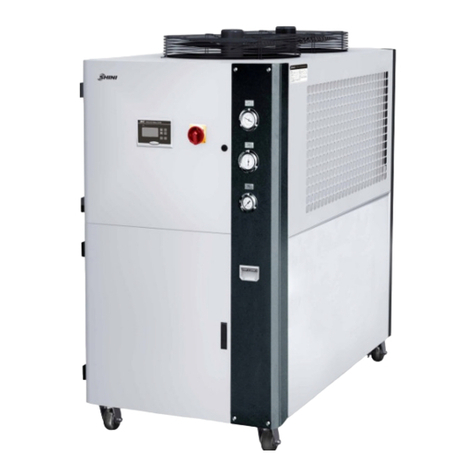
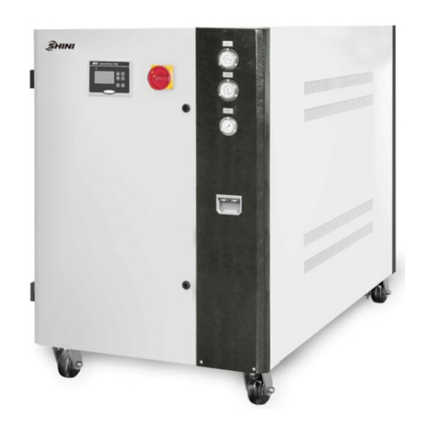
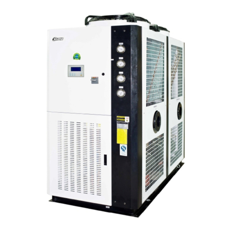
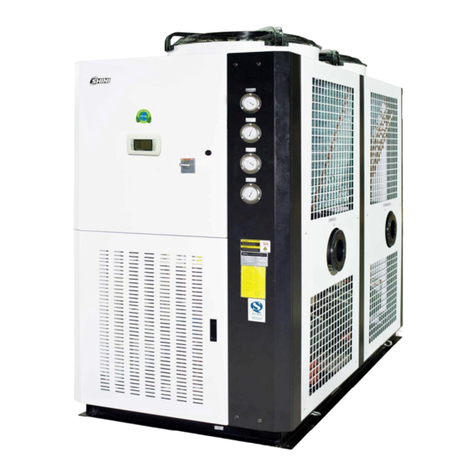
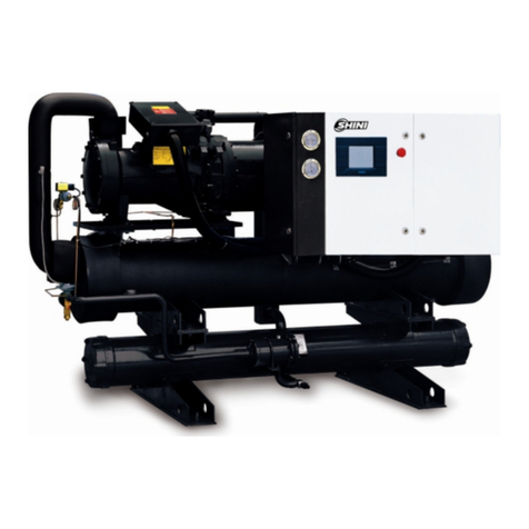
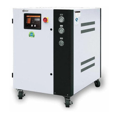
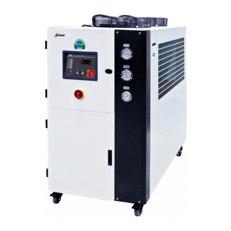
Shini SIC-A-R2 User manual

SIC-A-R2
Air-cooledWaterChiller
Date:Nov, 2014
Version: Ver.B(English)


3(96)
Contents
1. General Description.....................................................................................9
1.1 CodingPrinciple....................................................................................10
1.2 MainFeatures.......................................................................................10
1.3 TechnicalSpecifications........................................................................12
1.3.1 ExternalDimensionsofSIC-A-R2...............................................12
1.3.2 Specification List.........................................................................14
1.4 SafetyRegulations................................................................................15
1.4.1 SecurityLabels...........................................................................15
1.4.2 Signsand Labels........................................................................15
1.5 ExemptionClause.................................................................................16
2. Structural Features and Working Principle..............................................17
2.1 MainFunctions......................................................................................17
2.1.1 WorkingPrinciple........................................................................17
2.2 PartsDrawing........................................................................................19
2.2.1 StructureChart (SIC-7.5A-R2)....................................................19
2.2.2 StructureChart PartsList (SIC-7.5A-R2)....................................20
2.2.3 WaterSystemDiagram(SIC-7.5A-R2).......................................21
2.2.4 WaterSystemPartsList (SIC-7.5A-R2)......................................22
2.2.5 Refrigrant SystemDiagram(SIC-7.5A-R2).................................23
2.2.6 Refrigrant SystemPartsList (SIC-7.5A-R2)...............................24
2.2.7 GeneralAssemblyDiagram(SIC-7.5A-R2)................................25
2.2.8 GeneralAssemblyPartsList (SIC-7.5A-R2)...............................26
2.2.9 RackingDiagram(SIC-12A-R2).................................................27
2.2.10Rack PartsList (SIC-12A-R2).....................................................28
2.2.11WaterSystemDiagram(SIC-12A-R2)........................................29
2.2.12WaterSystemPartsList (SIC-12A-R2).......................................30
2.2.13RefrigerantSystemDiagram(SIC-12A-R2)................................31
2.2.14RefrigerantSystemPartsList (SIC-12A-R2)..............................32
2.2.15Rack Diagram(SIC-12A-R2)......................................................33
2.2.16Rack PartsList (SIC-12A-R2).....................................................34
2.2.17Rack Diagram(SIC-18A-R2~24A-R2)........................................35

4(96)
2.2.18Rack PartsList (SIC-18A-R2~24A-R2).......................................36
2.2.19WaterSystemDiagram(SIC-18A-R2~24A-R2)..........................37
2.2.20WaterSystemPartsList (SIC-18A-R2~24A-R2)........................38
2.2.21Refrigrant SystemDiagram(SIC-18A-R2~24A-R2)....................39
2.2.22Refrigrant SystemPartsList (SIC-18A-R2~24A-R2)..................40
2.2.23GenmeralAssemblyDiagram(SIC-18A-R2~24A-R2)................41
2.2.24GenmeralAssemblyPartsList (SIC-18A-R2~24A-R2)...............42
2.2.25Rack Diagram(SIC-28A-R2~38A-R2)........................................43
2.2.26Rack PartsList (SIC-28A-R2~38A-R2).......................................44
2.2.27WaterSystem& Refrigerant systemDiagram
(SIC-28A-R2~38A-R2)..........................................................................45
2.2.28WaterSystem& Refrigerant systemPartsList
(SIC-28A-R2~38A-R2)..........................................................................46
2.2.29Rack Diagram(SIC-48A-R2~75A-R2)........................................47
2.2.30Rack PartsList (SIC-48A~75A-R2)...........................................48
2.2.31WaterSystemDiagram(SIC-48A-R2~75A-R2)..........................49
2.2.32WaterSystemPartsList (SIC-48A-R2~75A-R2)........................50
2.2.33RefrigerantSystemDiagram(SIC-48A-R2~75A-R2)..................51
2.2.34RefrigerantSytemPartsList (SIC-48A-R2~75A-R2)..................52
2.2.35GeneralAssemblyDisgram(SIC-48A-R2~75A-R2)...................53
2.2.36GeneralAssembleDiagramPartsList (SIC-48A-R2~75A-R2)...54
2.2.37Rack Diagram(SIC-100A-R2)....................................................55
2.2.38Rack PartsList (SIC-100A-R2)...................................................56
2.2.39WaterSystemDiagram(SIC-100A-R2)......................................57
2.2.40WaterSystemPartsList (SIC-100A-R2).....................................58
2.2.41RefrigerantSystemDiagram(SIC-100A-R2)..............................59
2.2.42RefrigerantSytemPartsList (SIC-100A-R2)..............................60
2.2.43GeneralAssemblyDisgram(SIC-100A-R2)...............................61
2.2.44GeneralAssemblyDiagramPartsList (SIC-100A-R2)...............62
2.2.45Rack Diagram(SIC-114A-R2)....................................................63
2.2.46Rack PartsList (SIC-114A-R2)...................................................64
2.2.47WaterSystemDiagram(SIC-114A-R2)......................................65
2.2.48WaterSystemPartsList (SIC-114A-R2).....................................66
2.2.49RefrigerantSystemDiagram(SIC-114A-R2)..............................67

5(96)
2.2.50RefrigerantSytemPartsList (SIC-114A-R2)..............................68
2.2.51GeneralAssemblyDisgram(SIC-114A-R2)...............................69
2.2.52GeneralAssemblyDiagramPartsList (SIC-114A-R2)...............70
2.2.53MainPartsandFunctions...........................................................71
2.3 MainElectricalComponents.................................................................76
2.3.1 ThermalOverload Relay.............................................................76
3. Installation and Debugging........................................................................77
3.1 Installation Notices................................................................................77
3.2 SchematicDrawingofInstallation.........................................................78
3.3 PowerSupply........................................................................................78
4. Application and Operation.........................................................................79
4.1 ControlPanel........................................................................................79
4.2 Machine startup.....................................................................................81
4.3 Machine Shutdown................................................................................82
4.4 Thermostat1.........................................................................................83
4.4.1 TemperatureSetting...................................................................83
4.4.2 DefaultSettingTable..................................................................84
4.4.3 Code Meanings...........................................................................84
4.5 Condenserand EvaporatorCleaningStep............................................85
4.5.1 Tube-in-shell CondenserCleaning.............................................85
4.5.2 Tube-in-shell EvaporatorCleaning.............................................85
5. Trouble-shooting........................................................................................87
6. Maintenance and Repair............................................................................90
6.1 Fill inthe Refrigerant.............................................................................92
6.2 ComponentsMaintenance....................................................................93
6.2.1 Condenser..................................................................................93
6.2.2 Evaporator..................................................................................94
6.3 MaintenanceSchedule..........................................................................95
6.3.1 About theMachine......................................................................95
6.3.2 Check afterInstallation...............................................................95
6.3.3 DailyChecking............................................................................95
6.3.4 WeeklyChecking........................................................................95
6.3.5 MontlyChecking.........................................................................95

6(96)
6.3.6 TrimonthlyChecking...................................................................95
6.3.7 Half-yearlyChecking...................................................................96
6.3.8 YearlyChecking..........................................................................96
6.3.9 3yearChecking..........................................................................96
TableIndex
Table1-1: Specifications..................................................................................13
Table1-2: SpecificationList..............................................................................14
Table2-1 StructureChart PartsList (SIC-7.5A-R2).......................................20
Table2-2 WaterSystemPartsList(SIC-7.5A-R2).........................................22
Table2-3 RefrigrantSystemPartsList (SIC-7.5A-R2)...................................24
Table2-4 GeneralAssemblyPartsList (SIC-7.5A-R2)..................................26
Table2-5 Rack PartsList (SIC-12A-R2)........................................................28
Table2-6 WaterSystemPartsList(SIC-12A-R2)..........................................30
Table2-7 RefrigerantSystemPartsList (SIC-12A-R2)..................................32
Table2-8 Rack PartsList (SIC-12A-R2)........................................................34
Table2-9 Rack PartsList (SIC-18A-R2~24A-R2)..........................................36
Table2-10 WaterSystemPartsList (SIC-18A-R2~24A-R2)..........................38
Tabel2-11 RefrigrantSystemPartsList (SIC-18A-R2~24A-R2)....................40
Table2-12 GenmeralAssemblyPartsList (SIC-18A-R2~24A-R2)................42
Table2-13 Rack PartsList (SIC-28A-R2~38A-R2)........................................44
Table2-14 WaterSystem& RefrigerantsystemPartsList
(SIC-28A-R2~38A-R2)......................................................................................46
Table2-15 Rack PartsList (SIC-48A~75A -R2).............................................48
Table2-16 WaterSystemPartsList (SIC-48A-R2~75A-R2)..........................50
Table2-17 Refrigerant SytemPartsList (SIC-48A-R2~75A-R2)...................52
Table2-18 GeneralAssembleDiagramPartsList (SIC-48A-R2~75A-R2)....54
Table2-19 Rack PartsList (SIC-100A-R2)....................................................56
Table2-20 WaterSystemPartsList (SIC-100A-R2)......................................58
Table2-21 Refrigerant SytemPartsList (SIC-100A-R2)................................60
Table2-22 GeneralAssembleDiagramPartsList (SIC-100A-R2)................62
Table2-23 Rack PartsList (SIC-114A-R2)....................................................64
Table2-24 WaterSystemPartsList (SIC-114A-R2)......................................66

7(96)
Table2-25 Refrigerant SystemPartsList (SIC-114A-R2)..............................68
Table2-26 GeneralAssemblyDiagramPartsList (SIC-114A-R2).................70
PictureIndex
Picture1-1: Outline DimensionalDrawing........................................................12
Picture2-1:WorkingPrincipleDiagram............................................................17
Picture2-2 StructureChart (SIC-7.5A-R2).....................................................19
Picture2-3 WaterSystemDiagram(SIC-7.5A-R2)........................................21
Picture2-4 Refrigrant SystemDiagram(SIC-7.5A-R2)..................................23
Picture2-5 GeneralAssemblyDiagram(SIC-7.5A-R2).................................25
Picture2-6 Rack Diagram(SIC-12A-R2).......................................................27
Picture2-7 WaterSystemDiagram(SIC-12A-R2).........................................29
Picture2-8 Refrigerant SystemDiagram(SIC-12A-R2).................................31
Picture2-9 Rack Diagram(SIC-12A-R2).......................................................33
Picture2-10 Rack Diagram(SIC-18A-R2~24A-R2).......................................35
Picture2-11 WaterSystemDiagram(SIC-18A-R2~24A-R2).........................37
Picture2-12 Refrigerant SystemDiagram(SIC-18A-R2~24A-R2).................39
Picture2-13 GenmeralAssemblyDiagram(SIC-18A-R2~24A-R2)...............41
Picture2-14 SackDiagram(SIC-28A-R2~38A-R2).......................................43
Picture2-15 WaterSystem& RefrigerantsystemDiagram
(SIC-28A-R2~38A-R2)......................................................................................45
Picture2-16 Rack Diagram(SIC-48A-R2~75A-R2).......................................47
Picture2-17 WaterSystemDiagram(SIC-48A-R2~75A-R2).........................49
Picture2-18 Refrigerant SystemDiagram(SIC-48A-R2~75A-R2).................51
Picture2-19 GeneralAssemblyDisgram(SIC-48A-R2~75A-R2)..................53
Picture2-20 Rack Diagram(SIC-100A-R2)...................................................55
Picture2-21 Refrigerant SystemDiagram(SIC-100A-R2).............................59
Picture2-22 GeneralAssemblyDisgram(SIC-100A-R2)...............................61
Picture2-23 Rack Diagram(SIC-114A-R2)...................................................63
Picture2-24 WaterSystemDiagram(SIC-114A-R2).....................................65
Picture2-25 Refrigerant SystemDiagram(SIC-114A-R2).............................67
Picture2-26 GeneralAssemblyDisgram(SIC-114A-R2)...............................69
Picture2-27 Compressor...............................................................................71

8(96)
Picture2-28 Condensor.................................................................................71
Picture2-29 DryingFilter...............................................................................72
Picture2-30 Heat ExpansionValve................................................................72
Picture2-31 Evaporator.................................................................................72
Picture2-32 HighandLowPressureController.............................................73
Picture2-33 Refrigerant Indicator..................................................................73
Picture2-34 SolenoidValve...........................................................................73
Picture2-35 Heat By-pass Valve...................................................................74
Picture2-36 FlowSwitch................................................................................74
Picture2-119: ThermalOverlaod Relay............................................................76
Picture3-1 InstallationLocation.....................................................................78
Picture4-1 ControlPanel...............................................................................79
Picture4-2 StepupStep 1..............................................................................81
Picture4-3 Thermostat...................................................................................83
Picture6-1 Fill inthe Refrigerant (1)..............................................................92
Picture6-2 Fill inthe Refrigerant (2)..............................................................93

9(96)
1.General Description
Pleaseread throughthis operationmanualbeforeusingand installation to
avoiddamage of themachineandpersonalinjuries.
SIC-A-R2seriesareapplicableforcoolingmoldstoreduceproductsmolding
cycle, alsotheyareavailableinthecoolingofequipmentsinordertomaintaina
normaltemperature. Besides,theyaresuitableforotherindustrieswiththeneed
ofcooling.
Model: SIC-7.5A-R2

10(96)
1.1CodingPrinciple
1.2MainFeatures
1)Standardconfiguration
●Coolingrange7~25℃.
●Stainless steelmadeinsulted watertank.
●Anti-freezingthermostat.
●Adopt R410A refrigerant.
●Refrigerationloopcontrolledbyhighandlowpressureswitch.
●Compressorandpumpoverload relays.
●AdoptsItalianmadetemperaturecontrollermaintainsanaccuracyof 0.1℃.
●Lowpressurepumpsarestandardconfigurations.
●All adopt branded compressorswithlownoise, highefficiencyandlong
servicelife.
●SIC-A adoptsfinstylecondenserdesignwithout anyneedof coolingwater
forexcellent heattransferandrapidcooling.
2)Accessoryoption
●Mediumandhighpressurepumpsareoptionaltomeet anypressure
requirements.
●Leversensorof watertankisavailabletodetectthewaterlever.
●Hot-air bypass valvecanbeopted toreachtheaccuracyof±1℃.
●Solenoidvalveisoptionaltoprevent evaporatorfreezingbycuttingthe
refrigerant immediatelyafterdowntime.

11(96)
●Levelsensorcan beoptedtodetectthe refrigerantand ensureitsqualityand
waterratio.
●Optionalflowswitchtodetect chilled waterflow.
All serviceworkshouldbe carried out byaperson withtechnicaltrainingor
correspondingprofessionalexperience.The manualcontainsinstructionsforboth
handlingand servicing.Chapter7, whichcontainsserviceinstructionsintendedfor
serviceengineers. Otherchapterscontaininstructionsforthedailyoperator.
Anymodificationsofthemachinemustbe approved bySHINI inordertoavoid
personalinjuryand damagetomachine.Weshall not beliableforanydamage
causedbyunauthorized changeof themachine.
Ourcompanyprovidesexcellent after-salesservice. Shouldyou haveanyproblem
duringusingthemachine,pleasecontactthecompanyorthelocalvendor.
HeadquarterandTaipeifactory
Tel:(886)226809119
ShiniPlastics Technologies(Dongguan), Inc
Tel:(86)769 81116600
ShiniPlastics TechnologiesIndiaPvt.Ltd.
Tel:(91)250 3021166

12(96)
1.3Technical Specifications
1.3.1ExternalDimensionsofSIC-A-R2
SIC-7.5A-R2~SIC-38A-R2
SIC-48A-R2~SIC-75A-R2
SIC-100A-R2~SIC-114A-R2
Picture1-1: Outline DimensionalDrawing

13(96)
Table1-1: Specifications
Model H
(mm)
H1
(mm)
W
(mm)
W1
(mm)
W2
(mm)
D
(mm)
P1
Chilled
Water
Inlet
(inch)
P2
Chilled
Water
Outlet
(inch)
P3
Water
Tank
Outfall
(inch)
P4
Water
Tank
Overfall
(inch)
P5
Water
Tank
Refill
Port
(inch)
Weight
(kg)
SIC-7.5A-R2
1200
625
685
277
200
1190
1 1 1/2 1/2 1/2 305
SIC-12A-R2 1490
640
735
360
174
1320
1 1 1/2 1/2 1/2 315
SIC-18A-R2 1430
640
735
300
204
1610
11/211/21/2 1/2 1/2 400
SIC-24A-R2 1440
640
735
300
204
1610
11/211/21/2 1/2 1/2 420
SIC-28A-R2 1560
726
905
390
223
1782
11/211/21/2 1/2 1/2 530
SIC-38A-R2 1560
726
905
390
223
1782
2 2 1/2 1/2 1/2 540
SIC-48A-R2 1942
755
1208
400
257
2922
2 2 1 1/2 1/2 775
SIC-58A-R2 1942
755
1208
400
257
2922
2 2 1 1/2 1/2 800
SIC-75A-R2 1942
755
1208
418
257
2922
21/221/21 1/2 1/2 840
SIC-100A-R2
1942
641
1300
800
243
3475
21/221/21 1 1 1400
SIC-114A-R2
1942
641
1300
900
255
3475
21/221/21 1 1 1600

14(96)
1.3.2Specification List Table1-2: SpecificationList
Model
SIC-
Item/
Parameters 7.5A-R2
12A-R2
18A-R2
24A-R2
28A-R2
38A-R2
48A-R2
58A-R2
75A-R2
100A-R2
114A-R2
Refrigerant
Capacity1)
kW(50Hz/60Hz) 7.5 12 / 15
18
24 / 30
28 / 35.5
38 / 45
48 / 60
58 / 70
75 / 90
100 / 122
114 / 136
Refrigerant
Capacity2)
kW(50Hz/60Hz) 9.5 14 / 17.5
24 32 / 37.5
38 / 41
45 / 48
64 / 75
76 / 82
90/ 96
121 / 133.5
135 / 144
Type Scroll
Compressor
Power (50Hz/60Hz)
2.9 4.2 /
5.28 6.4 8.72 /
10.2
9.36 /
11.73
12.25 /
14.8
17.44 /
20.4
18.72 /
23.76
24.86 /
29.6 33.58 / 39.8
37.29 / 44.4
Weight (kg) 3.5 5.0 5.5 5.5 9.0 12.5 7.5 ×2
8 ×2
8 ×2
7.8 ×2 +
6.8 8.7 ×3
ControlMode Thermostatic expansionvalve
Refrigerant
Type R410A
Evaporator
Type Tube-in-shell style
Type Tube-finstyle
Condenser
Blower (kW)
(50Hz/60Hz) 0.19 0.55 /
0.91 2×0.23
2×0.385 /
2×0.57
2×0.6 /
2×0.91
2×0.78 /
2×1.1
2×1.03 /
2×2.2
2×0.85 /
2×2.2
2×1.92 /
2×2.2
2×2.2+1.5 /
2×2.2+2.2
3×2.2 /
3×2.2
Water Tank Capacity (L) 30 65 80 186
186
230
316
Power (kW) 0.75 / 0.75 / 1.1/
- / 0.75 / 1.5
1.1 / 1.1 / 1.1 /
- / 1.1 / 1.1
1.1 / 1.5 / 2.2 /
- / 2.2 / 2.2
2.2 / 1.8 / 2.4 /
- / 3.0 / 3.0
2.2 / 3.0 / 4.0 /
- / 5.5 / 5.5
2.2 / 4.0 /
5.5 /
- / 5.5 /5.5
Pump Flow (L/min)
40
- /83 / 67
80
- /100 / 89
120
- /150 / 133
190
- /300 / 300
320
- /300 / 300
378
- /366 / 367
Pump 2)
(50Hz/60Hz)
Working Pressure
(kg/cm2)
2.5 / 3.5 / 4.4 /
- / 2.6 / 3.8
2.5 / 3.5 / 4.1 /
- / 2.6 / 3.5
2.2 / 3.5 / 4.4 /
- / 3.0 / 4.2
2.2 / 3.1 / 4.4 /
-/ 3.0 / 4.2
2.3 / 3.0 / 4.0 /
- / 3.0 / 4.2
2.2 / 3.2 /
4.4 /
- / 3.4 / 4.3
TotalPower (kW) (50Hz/60Hz) 3.85 5.5 /
5.86 8.0
10.6 /
12.44
11.66 /
15.74
15 / 19.2
21 / 27.8
22.6 /
30.86
30 / 39.5
41.7 / 51.9
46 / 53.51
CoolingWater Outlet
(50Hz/60Hz) 1 / 1 11/2/ 11/22 / 2 2.5 / 2.5
Water Tank Inlet
(50Hz/60Hz) 1 / 1 11/2/ 11/22 / 2 2.5 / 2.5
Water Tank Inlet 1/2 1
Pipe
Coupling
(inch)
Water Tank Overflow
1/2 1
Compressor Overload relay
Pump Overload relay
CoolingWater Circuit
Highand low pressure switch/anti-freeze switch
Protective
Devices
Water Circuit Water levelswitch(Optional)/By-pass valve
OperationNoise dB (A) 78 75 74 78 81 86 84 82 86 90 90
Power(VAC) 3Φ, 400VAC, 50Hz
Measures Exchange 1 kW=860 kcal/hr1 RT =3,024 kcal/hr10,000 Btu/hr =2,520 kcal/hr
Note:
1) Refrigeration capacityis measuredbasedon the flow0.172m3/ (h.kW) and the outlet temperature(7℃)
of chilled water under the environment temperatureof35℃.

15(96)
2) LowpressurepumpisfordomesticandSoutheast Asiaexport, customerscan change for medium
pressurepumps(useP forshort; e.g.: SIC-and A-R2-P) or high pressurepumps(useHP for short; e.g.:
SIC-and A-R2-HP), specific parametersin turnasshownabove.
3) Pumppower isincluded in total power.
4) Specialordersof machine voltagecan beacceptable according tocustomers’requests.
5) The air-cooled water chilleris applicable totheconditionsunder the environmenttemperatureof 43℃.
1.4 SafetyRegulations
Theusermust conformtothefollowingsafetyruleswhen operatingthe
machine.
1.4.1SecurityLabels
Attention!
Installation of the deviceisallowed onlytotheprofessionalelectrician.
Beforemaintainingandrepairingthedevice, be suretoturnoffthemain
switchand controlswitch.
Warning! HighVoltage!
Thislabelisposted on enclosureoftheelectricalcontrolcabinet!
Warning! Becareful!
Paymoreattentionsatthe placeswherethissignisattached!
Attention!
Drainthe waterinsidewhen poweroffat thecolddaytoavoidfreezing!
Attention!
Noneed forregularinspectionbecauseall theelectricalpartsinthe
controlunit arefixed tightly!
1.4.2Signsand Labels
Thisisforindicatingmotorrotating
direction.
When phasereversalhappens, thealarm
soundsandindicatoroncontrolpanelwill
indicate. Pleaseexchangetheplaceof
the twoelectricalwirestosolvethis
problem.

16(96)
Pumppressuregauge:displayactual
pressureofcoldwatersystem.
Highpressuregauge:displaypressurein
the high-pressuresideofrefrigerant
system.
Lowpressuregauge:displaypressurein
the low-pressuresideofrefrigerant
system.
1.5 Exemption Clause
Thefollowingstatementsclarifytheresponsibilitiesandregulationsbornbyany
buyeroruserwho purchasesproductsandaccessoriesfromShini(including
employeesandagents).
Shiniisexempted fromliabilityforanycosts,fees,claimsandlossescausedby
reasonsbelow:
1. Anycarelessorman-madeinstallations,operation andmaintenancesupon
machineswithoutreferringtothe Manualpriortomachineusing.
2. Anyincidentsbeyondhumanreasonablecontrols, whichincludeman-made
viciousordeliberatedamagesorabnormalpower,and machine faultscaused
byirresistiblenaturaldisastersincludingfire,flood,stormand earthquake.
3. Anyoperationalactionsthatarenotauthorized byShiniuponmachine,
includingaddingorreplacingaccessories, dismantling,deliveringorrepairing.
4. Employingconsumablesoroil mediathatarenotappointed byShini.

17(96)
2.Structural Features and Working Principle
2.1MainFunctions
SIC-A-R2seriesareapplicableforcoolingmoldstoreduceproductsmolding
cycle,alsotheyareavailableinthecoolingofequipmentsinordertomaintaina
normaltemperature.Besides,theyaresuitableforotherindustrieswiththe
needof cooling.
2.1.1WorkingPrinciple
Picture2-1:Working PrincipleDiagram
When the SIC-A-R2air-cooled waterchillerstartingup, compressorstarts
working. Refrigerant iscompressed intohightemperaturehighpressuregasin
the process fromB toC, andthen be cooledwhen passingthroughthe
condenserandchangedintoliquid.Heat istaken awaybythe cooling air.Inthe
process fromCtoDtoE andF,theliquidrefrigerant isdried andfiltered bythe
dryfilter. Afterthat, itpassesthroughthe solenoidvalve, levelsensorand then
reachestheexpansion valve. Inthe process fromFtoG,thehighpressure
liquidrefrigerantisthrottled anddepressurized bytheheatexpansionvalveand
the temperaturegoesdown. Inthe process ofG toA, chilled waterabsorbsthe
heatofprocess waterintheevaporatorand returnsback tothe compressor.
Thisheat exchangeprocess repeatsuntil process wateriscooleddownto
required temperature.

18(96)
Hot-air bypass function: thecompressorcontinuesworkingwhen theprocess
wateriscooled downtotherequired temperature,thenthehot-air bypass valve
opensasthetemperaturedropstoitssetvalue. Apartoftherefrigerantfrom
the compressorpassesthroughthe bypass valveand thenreachthe
evaporator,balancingoutpart of themachinerefrigeratingcapacityand then
goesback tothe compressorwithout passingthroughthe condenser.Withthe
helpofhot-air bypass valve, the systemcanstayinan balanced conditionand
meanwhilecan keep thecontrolaccuracyat ±1℃.

19(96)
2.2 Parts Drawing
2.2.1StructureChart (SIC-7.5A-R2)
Note: For detailsofthe numbersinthe partsdrawing, please refer tothe part list in2.2.2
Picture2-2 StructureChart (SIC-7.5A-R2)

20(96)
2.2.2StructureChart PartsList (SIC-7.5A-R2)
Table2-1 StructureChart PartsList (SIC-7.5A-R2)
No.
Name PartsNo. No.
Name PartsNo.
1 Brakingblackcastor 3”
YW03000300000
18
Movable blackcastor
3”PP YW03000300200
2 Triangle support (left) - 19
Middle backbeam -
3 Water tank - 20
Electric control cabinet
support -
4 Water tankCover - 21
Right frontstandstand
column -
5 Left part ofmiddle
beam - 22
Electric control cabinet -
6 Fan cover 1 - 23
Top plate -
7 Left frontstandstand
column - 24
Baseplateofelectric
control cabinet -
8 HexboltM6×20 YW60062000100
25
ScrewM6×20 YW62062000000
9 Fan guide - 26
HexnutM8 YW64080600000
10
Fan cover 3 - 27
Spring washer 8 YW65008000100
11
Back stand stand
column - 28
Flat washer8 YW66082200100
12
Fan cover 2 - 29
Baseframe -
13
HexboltM8×20 YW60082000300
30
Right part ofmiddle
beam -
14
Condensorsupport - 31
Lower beam1 -
15
Squarehandle BW20012000040
32
Lower beam2 -
16
ScrewM6×10 YW62061000000
33
Middle lower beam -
17
Triangle support
(right) - 34
Lower beam3 -
*means possiblebrokenparts. ** means easybroken parts. Sparebackup issuggested.
Please confirmthe versionnumber ofthe manualbeforeyou order toensurethe stock
number and the partsareconsistent.
Table of contents
Other Shini Chiller manuals
Popular Chiller manuals by other brands

Johnson Controls
Johnson Controls SABROE ChillPAC operating manual

Daikin McQuay
Daikin McQuay AWS210BDS installation manual

CLIVET
CLIVET WSH Series Installation, use and maintenance manual

CLIVET
CLIVET WSAT-XEE Series Installation and use manual

Daikin
Daikin EWYD-BZ operating manual

Elkay
Elkay HCR8*1J installation instructions