S&A CWFL-2000 User manual

CWFL-2000
DUAL TEMPERATURE AND
ONE PUMP INDUSTRIAL CHILLER
USER MANUAL

CWFL-2000 Series
2
Contents
<1> Cautions ---------------------------------------------------------------- 3
<2> Contour and parts introduction -------------------------- ------- 4
<3> Installation -------------------------------------------------------------- 5
<4> Operation and parameters adjustment ----------------------- 6
<5> Alarm and output terminal ----------------------------------------- 10
<6> Specifications -------------------------------------------------------- 11
<7> Simple troubleshooting -------------------------------------------- 12

CWFL-2000 Series
3
Thank you for using the machine from GUANGZHOU TEYU
ELECTROMECHANICAL CO., LTD. Please read the installation instructions
carefully before installing and operating and keep it properly.
This installation instructions is not a quality assurance. GUANGZHOU TEYU
ELECTROMECHANICAL CO., LTD reserves the right to the interpretation of
correction of typographical errors, improper mentioned information and product
improvement. The amended content will be reprinted in installation instructions
without notice in advance.
<1> Cautions
1. Please ensure that the power supply and electrical outlet are in good contact
and the earth wire must be firmly grounded!
2. Please make sure there is stable and normal voltage for the working chiller!
As the refrigeration compressor is more sensitive to the power supply and
voltage, so the operating voltage of our standard product is ±10%of the rated
voltage. If you do need a wider operating voltage range, customization is
available for us.
3. Unmatched power frequency can cause the chiller damage!
Please choose model of 50Hz or 60Hz according to actual circumstance.
4. To protect the pump, it’s strictly forbidden to run the chiller without water in the
storage water tank!
The new machine is packed after draining whole water in the tank, so please
make sure the tank has water inside before machine starting, otherwise it’s
easily to have the pump damaged. When the water level is below the green
(NORMAL) range of the water level gauge, the cooling capacity of our chiller
will go down slightly. Hence please ensure the water level is within the green
(NORMAL) range. To drain through circulating pump is strictly prohibited!
5. Please be sure that the air inlet and air outlet are in good ventilation!
There must be at least 50cm from obstructions to the air outlet which is in the
back of the cooler, and should leave at least 30cm between obstructions and
the side air inlet.
6. The filter gauze must be regularly cleaned!
It’s essential to remove and wash the dust gauze regularly, otherwise chiller
malfunction can be caused by serious blockage.
7. Please pay attention to the effect of the condensate water!
With greater ambient humidity, when the water temperature is lower than the
ambient temperature, the condensate water will generate on the surface of
water circular pipes and the cooled components. If above circumstance
appears, it is recommended to set a higher water temperature or keep pipes
and cooled parts warm.
8. This product is an industrial equipment.For professional use only.

CWFL-2000 Series
4
<2> Contour and parts introduction
AIR INLET
(FILTER GAUZE)
POWER SUPPLY
ALARM OUTPUT
WATER OUTLET (H)
WATER INLET (H)
DRAIN
WATER LEVEL GAUGE
WATER SUPPLY INLET
AIR OUTLET
WATER INLET (L)
WATER OUTLET (L)
FILTER
POWER SWITCH
HIGH TEMP
LOW TEMP
WATER PRESSURE
GAUGE

CWFL-2000 Series
5
<3> Installation
It is very simple to install this industrial cooling machine. The installation for the
first time of the new machine can be carried out by following steps:
1. Open the package to check if the machine is intact and all the necessary
accessories are completed.
2. Open the water supply lid to feed cooling water.
Observing the water level gauge to feed water slowly, be careful not to have the
water overflowed!
3. According to system conditions, please connect the water inlet and outlet pipe
properly.
4. Plug in power, turn on the power switch. (Do not start up without water in the
water tank!)
(1) Power switch turned on, the circulation pump of the chiller starts working. The
first time of operating may cause more bubbles in the pipe leading to a flow
alarming occasionally, but running for a few minutes later, it will go back to
normal.
(2) If the chiller starts for the first time, you must immediately check whether the
water pipe leaks.
(3) Power switched on, if the water temperature is under the set value, it is normal
that fans and other components of the machine do not work. The temperature
controller will automatically control the working conditions of the compressor,
magnetic valve, fans and other parts based on the set controlling parameters.
(4) As it takes a longer time to start over the compressor and other components,
according to different conditions, the time is range from seconds to minutes, so
do not turn on and off frequently.
5. Check the water level in the water tank.
The first starting up of a new chiller will empty the air in the water pipe, causing
a slight water level decline, but in order to keep the water level in the green area,
it is allowed to add adequate water again. Please observe and record the current
water level, and inspect it again after the chiller running for a period of time, if
the water level drops obviously, please re-inspect the water pipeline leakage.
6. Adjust parameters of temperature controller.
CWFL-2000 series use an intelligent thermostat. Normally users do not need to
adjust the parameters. If it is necessary, please refer to page 6 , “Operating
status and parameters adjustment.”

CWFL-2000 Series
6
<4> Operation status and parameters
adjustment
The new T506 intelligent temperature controller does not need to adjust the
controlling parameters under normal circumstance. It will self-adjust
controlling parameters according to room temperature for meeting equipment
cooling requirements.
The new T506H intelligent temperature controller is selected constant
temperature control mode as factory setting with water temperature at 25℃.
User can adjust it as needed.
T506 and T506H controllers are of same functions and structure except
default setting.
1. Temperature control panel introduction
(1). Indicators of temperature controller working status:
COMP ON, compressor working
SV ON, solenoid valve working
Heating ON, heating rod working
INT Ctrl ON, controller working in intelligent control mode
CT Ctrl ON, controller working in constant temperature control mode
PARAM Set ON, controller working in parameters setting mode
ALM OUT ON, alarm output status
Room Temp ON, displaying room temperature
ST DLA ON, starting up delay status
(2). Press key to show the room temperature, 6 seconds later default
display restored. (Meanwhile, Room Temp light is on, displaying room
temperature.)
(3). keys are for modifying parameters values and keys
are for switching parameter items.

CWFL-2000 Series
7
(4). RST key: confirm
(5). SET key: setting function
2. Restore to factory settings
Before machine startup, press and hold keys until the controller
displays rE, 6 seconds later after releasing the keys, the controller works in
normal order. All parameters values settings of the controller have been
restored to factory settings.
3. Alarm function
(1) Alarm Display:
When alarm occurs, the error code and the temperature will be alternately
displayed.
E1
E2
E3
E4
E5
E6
Ultrahigh
room
temperature
Ultrahigh
water
temperature
Ultralow
water
temperature
Room
temperature
sensor failure
Water
temperature
sensor failure
External
alarm input
(2) To suspend the alarm:
In alarming state, the alarm sound could be suspended by pressing any button,
but the alarm display remains until the alarm condition is eliminated.
4. Temperature controller parameters list
Order
Code
Item
Range
T-506
Temperature
controller
Factory Setting
T-506H
Temperature
controller
Factory Setting
Note
1
F0
Temperature
setting
F9~F8
30
25
Constant
temperature
control effecting
2
F1
Temperature
Difference values
-15~+5
-2
-2
Intelligent control
effecting
3
F2
Cooling
hysteresis
0.1~3.0
0.3
0.3
4
F3
Way of control
0~1
1
0
1: intelligent
0: constant
temperature
5
F4
Alarm for ultrahigh
water temperature
1~20
20
10
6
F5
Alarm for ultralow
water temperature
1~20
20
15
7
F6
Alarm for ultrahigh
room temperature
40~50
45
45
8
F7
Password
00~99
8
8
9
F8
The allowed highest
water temperature
(F9+1)
~40
35
30
10
F9
The allowed lowest
water temperature
1 ~(F8-1)
25
20

CWFL-2000 Series
8
5. General settings adjustment
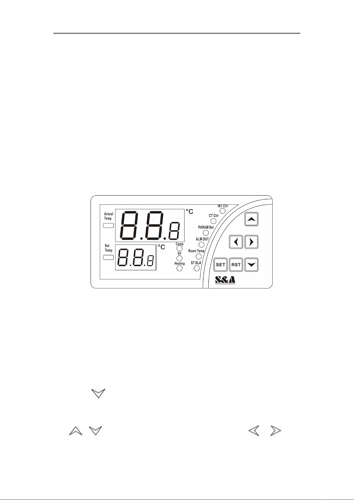
Press SET key to enter into the user-defined state. Meanwhile, PARAM SET is
on, controller in parameters setup status.
(1) Under intelligent mode, the control panel displays the temperature difference
value between water and air (default value is -2).
(2) Under constant temperature mode ,the control panel displays the set
temperature value (default value is 25).
At this moment, press keys to change settings. After modifying the
value, press RST key to save and exit, then new parameters take effect, or
press SET key to exit without saving parameters. If there is no more action
within 20 seconds, it will automatically exit modifying status without saving
parameters.
6. Advanced settings adjustment
(1) Press and hold the key while press SET key for 5 seconds until 00
displayed in upper window and PAS in lower window. Then press
keys to select the password (default setting is 8), and then press the SET key, if
the password is correct, F0 displays, entering into setup status, D1 flashing to
indicate that the controller is under parameters setup status. If the password is
incorrect, it returns to temperature display.
(2) Enter setup state, press keys to switch parameter items
circularly, then press keys to modify the parameter values. Press
enter key RST at any time to exit parameters setup with saving modified
parameters and return to temperature display, then chiller runs under the new
parameters. If no key is pressed within 20 seconds, the controller will
automatically exit parameters setup without saving the modified parameters
(under parameters setup status, system running in original parameters). Under
parameters setup status, SET key does not work.
Note:
1. During parameters setting condition, system runs under original parameters.
2. Under constant temperature control mode, the water temperature is controlled by
parameter F0;
3. Under intelligent control mode, the water temperature will be automatically
adjusted according to temperature changes. The temperature difference is
commanded by F1.

CWFL-2000 Series
9
7. Advanced parameters adjustment cases:
(1) Case 1: cooling water temperature is controlled by constant mode. Requiring
water temperature is constant in 28℃, and the fluctuate does not exceed ±2℃.
The alarm of over high water temperature will be on when water temperature is
5℃higher than normal value, and the alarm of over low water temperature will
be on when water temperature is 10 ℃lower than normal value. It is
convenient for user to adjust the water temperature between 5-30℃.
(2) Case 2: cooling water temperature is controlled by constant mode. Requiring
water temperature is constant in 20℃, and the fluctuate does not exceed ±1℃.
The over high water temperature will be on when water temperature is higher
than 25℃, and the alarm of over low water temperature will be on when water
temperature is lower than 5℃. (Regardless of what is the ambient temperature,
the cooling water temperature is constant in 19℃to 21℃)
Order
Code
Item
Value in
case 1
Value in
case 2
T-506
Temperature
controller
Factory Setting
T-506H
Temperature
controller
Factory Setting
1
F0
Temperature
setting
28
20
30
25
2
F1
Temperature
Difference values
-2
-2
3
F2
Cooling
hysteresis
2.0
1.0
0.3
0.3
4
F3
Way of control
0
0
1
0
5
F4
Alarm for over high
water temperature
5
4
20
10
6
F5
Alarm for over low
water temperature
10
14
20
15
7
F6
Alarm for over high
Room temperature
45
45
45
45
8
F7
Password
8
8
8
8
9
F8
The allowed highest
water temperature
30
30
35
30
10
F9
The allowed lowest
water temperature
5
5
25
20

CWFL-2000 Series
10
<5> Alarm and output terminal
In order to guarantee the equipment will not be effected while abnormal
situation happens on the chiller, CWFL-2000 dual temperature and dual pump
series chillers possess alarm protection function.
1. Alarm output terminals and wiring diagram.
2. Alarm causes and working status table.
Note: The flow alarm is connected to the normally open relay and normally closed
relay contacts, requiring operating current less than 5A, working voltage less
than 300V.
Display
Condition
Alarm code
Buzzer
OUT
H1、H2
OUT
H1、H3
Circulating pump works
properly
DISCONNECTION
BREAKOVER
Blocked cooling water
circulation loop
E6
Sounds
BREAKOVER
DISCONNECTION
Alarm of water shortage
E6
Sounds
BREAKOVER
DISCONNECTION
Faulted circulating
pump
E6
Sounds
BREAKOVER
DISCONNECTION
Ultrahigh room temp
E1
Sounds
BREAKOVER
DISCONNECTION
Ultrahigh water temp
E2
Sounds
BREAKOVER
DISCONNECTION
Ultralow water temp
E3
Sounds
BREAKOVER
DISCONNECTION
Faulted room temp
sensor(constant temp
invalid)
E4
Sounds
BREAKOVER
DISCONNECTION
Faulted water temp
sensor
E5
Sounds
BREAKOVER
DISCONNECTION
Chiller power failure
BREAKOVER
DISCONNECTION

CWFL-2000 Series
11
<6> Specifications
CWFL-2000
Model
CWFL-2000AN
Voltage
AC 1P 220 V
Frequency
50 Hz
Current
5.2~20.7A
Compressor power
2.23 KW
3.08 HP
Nominal cooling
capacity
23440 Btu/h
6.87 KW
5907 Kcal/h
Refrigerant
R-22/R-410a
Refrigerant charge
1800 g
Precision
±0.5℃
Reducer
Capillary
Protection
Overcurrent protection for compressor, flow alarm, over temperature alarm
Pump power
0.75 KW
Tank capacity
15 L
Inlet and outlet
Rp1/2”+Rp1”
Max. lift
53M
Max. flow
70 L/min
N.W
120 Kgs
G.W
155 Kgs
Dimension
85X60X103 cm (L X W X H)
Package dimension
95X70X125 cm (L X W X H)

CWFL-2000 Series
12
<7> Simple troubleshooting
Failure
Failure Cause
Approach
Machine turned on but
unelectrified
Power cord is not plugged in place
Check and ensure the power interface
and the power plug is plugged in place
and in good contact.
Fuse burnt-out
Open the electric box cover, check the
protective tube, replace with spare one
if necessary and check whether the
power supply voltage is stable; Check
and ensure the power interface and the
power plug are in good contact.
Flow Alarm
(controller displays E6) use a
water pipe directly connect
to the water outlet and inlet
but still without water
flowing
Water level in the storage water tank is
too low
Check the water level gauge display,
add water until the level shown in the
green area; And check whether water
circulation pipe leaks.
Flow alarm occurs while
running with other
equipment
(controller displays E6), but
there is water flowing and no
alarm when use a water pipe
directly connected to the
chiller water outlet and inlet.
Water circulation pipes are blocked or
a pipe bending deformation.
Check water circulation pipe
Ultra-high temperature alarm
(controller displays E2)
Blocked dust gauze, bad thermolysis
Unpick and wash the dust gauze
regularly
Poor ventilation for air outlet and inlet
To ensure a smooth ventilation
for air outlet and inlet
Voltage is extremely low or astable
To improve the power supply circuit or
use a voltage regulator
Improper parameter settings on
thermostat
To reset controlling parameters or
restore factory settings
Switch the power frequently
To ensure there is sufficient time
for refrigeration
(more than 5 minuets)
Excessive heat load
Reduce the heat load or use other
model with larger cooling capacity
Alarm for ultra-high room
temperature (controller
displays E1)
The working ambient
temperature is too high for the chiller
To improve the ventilation to guarantee
that the machine is running under 40℃.
Serious problem of
condensate water
Water temperature is much lower than
ambient temperature, high humidity
Increase water temperature or
to preserve heat for pipeline
Water drains slowly from
outfall during water
Injection port is not open
Open the injection port

CWFL-2000 Series
13
changing
CWFL-2000
双温双泵系列工业冷水机
使用安装说明书

CWFL-2000 Series
14
目 录
一.使用注意事项 -------------------------------------------------------------- 15
二.部件介绍 -------------------------------------------------------------------- 16
三.安装说明 -------------------------------------------------------------------- 17
四.运行状况与参数调整 ----------------------------------------------------- 18
五.报警与输出端口 ---------------------------------------------------------- 22
六.技术参数 -------------------------------------------------------------------- 23
七.简单故障处理 -------------------------------------------------------------- 24

CWFL-2000 Series
15
感谢您购买广州特域机电有限公司的产品,请在使用前仔细阅读使用安装说
明书,并妥善保管。
本使用安装说明书并非质量保证书,对印刷错误的更正,所述信息谬误的勘
误,以及产品的改进,均由广州特域机电有限公司随时做出解释,恕不预先通知,
修正内容将编入再版使用安装说明书中。
一、使用注意事项
1、请确保电源插座接触良好并且地线可靠接地!
2、请确保冷水机的工作电压稳定、正常!
由于制冷压缩机对电源电压比较敏感,我公司标准产品的正常工作电压为额
定电压±10%。如果确实需要更宽的工作电压范围,可以另行定制。
3、电源频率不匹配会导致机器损坏!
请根据实际情况,使用 50Hz 或60Hz 的机型。
4、为保护循环水泵,严禁无水运行!
新机装箱前都排空了储水水箱,请确保水箱注水后再开机,否则水泵极易损
坏。当水箱水位在水位计绿色(NORMAL)范围以下时,冷却机制冷量会轻
微下降,请保证水箱水位在水位计的绿色(NORMAL)范围内。严禁使用循
环泵排水!
5、请确保冷水机入风、出风通道顺畅!
冷水机上面的出风口距离障碍物要留有 50cm 以上的距离,侧面的入风口离
障碍物要求距离在 30cm 以上。
6、入风口的滤网必须定期清洗!
必须定期拆洗防尘网,防尘网严重堵塞会引起冷水机故障。
7、请注意冷凝水的影响!
当水温低于环境温度,并且环境湿度较大时,循环水管与被冷却器件表面会
产生冷凝水。当出现以上情况时,建议调高水温或对水管与被冷却器件进行保
温。
8、本产品为工业设备,请勿让非专业人士操作。

CWFL-2000 Series
16
二、 外形及部件名称
电源开关
温度控制器(低温)
温度控制器(高温)
水压表
入风口(滤网)
注水口
电源
低温冷却水出口
高温冷却水入口
出风口
排水口
水位计
流量报警输出
低温冷却水入口
高温冷却水出口
过滤器

CWFL-2000 Series
17
三、安装说明
冷水机安装使用非常简单,新机首次使用可按以下步骤进行:
1、打开包装,检查机器是否完好,附件是否齐备。
2、拧开机器注水口,加入冷却水。
加水时应同时观察水位计的水位慢慢加水,注意不要让水溢出!
3、根据设备情况接好出水管、入水管。
4、插上电源线,打开电源开关。(严禁无水开机!)
(1)打开电源开关后,冷水机循环泵就开始工作了。新机第一次开机时管路中
会有较多的气泡导致机器偶尔流量报警,运行数分钟后就会恢复正常。
(2)第一次开机后,必须马上检查水管管路有无漏水。
(3)打开电源后,如果水温低于设定温度,机器的风扇等器件不工作是正常现
象。温控器会根据设定的控制参数自动控制压缩机、电磁阀、风扇等器件
的工作状态。
(4)由于压缩机等器件有一个较长的启动过程,根据不同的工况从几十秒到数
分钟不等,所以不要频繁开关机。
5、检查水箱水位。
新机开机后排空了水管中的空气,水箱水位会略有下降,为了保持水位在
绿色区域,可以再次适量加水。观察并记下当前的水位情况,等冷水机运行
一段时间后再次观察水位计,如果水位下降明显,就要再次检查水管管路的
渗漏情况。
6、调整温控器参数。
CWFL-2000 双温单泵系列冷水机使用的智能温控器一般情况下不需要调
整控制参数,如确实必要的,可参考第 18 页《运行状况与参数调整》。

CWFL-2000 Series
18
四、运行状况与参数调整
T-506 新型智能控制器一般情况下不需要调整控制参数,它会根据室温的
变化自动调整控制参数,保证满足设备的冷却要求。
T-506H 新型智能控制器出厂设定为恒温温控模式,水温设定为 25 度,用
户可以根据需要调整。
T-506、T-506H 温控器除出厂设定参数不同外,其功能、结构是一样的。
1、温度控制器面板介绍
(1) 温控器工作状态指示灯(如图)
Comp 指示灯亮, 表示压缩机启动。
SV 指示灯亮, 表示电磁阀启动。
Heating 指示灯亮, 表示电发热棒启动。
INT Ctrl 指示灯亮, 指示控制器工作在智能控制模式;
CT Ctrl 指示灯亮, 指示控制器工作在恒温控制模式;
PARAM Set 指示灯亮, 指示控制器工作在参数设定模式;
ALM OUT 指示灯亮, 指示报警输出状态;
Room Temp 指示灯亮, 指示显示室温状态;
ST DLA 指示灯亮, 指示处于开机延时状态;
(2)按 键会显示室温温度,6秒后恢复默认显示。
(此时“Room Temp”亮,表明显示为室温。)
(3) 键变更参数值, 变更参数项。
(4)“RST” 键 确定按键
(5)“SET” 键 设定功能按键

CWFL-2000 Series
19
2、恢复出厂设定
开机前,同时按下“ ”键不放然后开机,直至控制器显示“rE”。
松开按键 6秒后控制器进入正常的工作状态。这时控制器所有参数设定值均已
恢复为出厂设定值。
3、报警功能
(1)报警显示:
报警时,出错的代码与水温会交替显示。
(2)暂停报警声:
在报警状态下按任何键均可停报警声响,但报警显示需等到报警条件消除
后才停止。
4、温控器控制参数表
次序
代码
设定项目
范 围
高温端
T-506 温控器
出厂设定
低温端
T-506H 温控器
出厂设定
备 注
1
F0
设定温度
F9~ F8
30
25
恒温工作模式有效
2
F1
温差数值
-15~+5
-2
-2
智能控制方式有效
3
F2
制冷回差
0.1~3.0
0.3
0.3
4
F3
控制方式
0~1
1
0
1智能、0恒温
5
F4
水温超高报警
1~20
20
10
6
F5
水温超低报警
1~20
20
15
7
F6
气温超高报警
40~50
45
45
8
F7
密码
00~99
8
8
9
F8
最高设定水温
(F9+1)~40
35
30
10
F9
最低设定水温
1 ~(F8-1)
25
20
E1
E2
E3
E4
E5
E6
室温超高
水温超高
水温超低
室温传感器故障
水温传感器故障
外部报警输入

CWFL-2000 Series
20
5、一般设定调整
按设定键“SET”进入用户设定状态,此时 “PARAM Set” 灯亮,表明现
在控制器为参数设定状态
(1)智能模式下显示水温与气温的温差参数值。(出厂设定值为-2)
(2)恒温模式下显示设定水温的数值。(出厂设定值为 25)
此时按“ ”键可修改设定值,修改数值后按下确认键“RST”
后存盘退出,新参数生效。如 20 秒内无按键按下,不保存参数自动退出修改
状态。
6、高级设定调整
(1)按住“ ”键不放,同时按设定键“SET”五秒至上限窗显示“00”,
下显示窗显示“PAS”,此时按“ ”键选择已设定密码(出厂
设定为 8),再按一下设定键“SET”,如密码正确,显示转为“F0”,进
入设定状态,表明现在控制器为参数设定状态。如密码错误,则返回温度
显示。
(2)进入设定状态后按“ ”键循环依次改变参数项,按键
“ ”则更改该参数项的参数值。任何时候按确定键“RST”,
则保存修改的参数退出参数设定状态,返回温度显示,并按新参数运行。
如20秒内无按键按下,控制器也会自动退出参数设定状态,并且不保存修
改的参数。(在参数设定状态时,系统按原参数运行。),在参数设置状态下,
按“SET”键不响应。
注:1、在参数设定状态时,系统按原参数运行;
2、恒温控制模式时,水温由“F0”参数控制;
3、智能控制模式时,水温会根据气温变化自动调整。其温差由“F1”参数
控制。
Table of contents
Other S&A Chiller manuals

S&A
S&A CWFL-6000 User manual

S&A
S&A CW-6080 User manual

S&A
S&A CW-5000 Series Installation instructions

S&A
S&A CWUL-05 User manual

S&A
S&A CW-6000AN250S01 User manual

S&A
S&A CWFL-500 User manual

S&A
S&A CWFL-4000 User manual

S&A
S&A CW-5000 Series Setup guide

S&A
S&A CW-5300 Installation instructions

S&A
S&A CWFL-3000 User manual
Popular Chiller manuals by other brands

Carrier
Carrier AQUASNAP 30RB060-390 Controls, start-up, operation, service and troubleshooting instructions

MTA
MTA MCCY-CY013 301 Operating and maintenance manual

Johnson Controls
Johnson Controls York YCIV A Series Installation operation & maintenance

Elkay
Elkay ER2-1C/2C installation instructions

AERMEC
AERMEC WRL 200 Technical manual

Modena
Modena CG 3180 User manual book