Shipsonic Heavy Duty Series User manual

Distributors for:
Ultrasonic AntiFouling Protection Systems
www.mgpsltd.com
HDS20 INSTALLTION GUIDE

Heavy Duty Series (HDS) Installation and user guide
HDS20 (2 transducer of 100 Watt or 120 Watt)
Contents
Delivery________________________________________________________________________ 3
Parts list________________________________________________________________________ 3
System dimensions and weights ____________________________________________________ 3
Product overview outside _________________________________________________________ 4
Product overview inside __________________________________________________________ 4
System identication _____________________________________________________________ 5
Installation _____________________________________________________________________ 5
Planning _______________________________________________________________________ 5
Installation of the control unit ______________________________________________________ 5
Transducer cable ________________________________________________________________ 6
Activation ______________________________________________________________________ 6
Schematic electrical diagram_______________________________________________________ 7
Maintenance checklist ____________________________________________________________ 7
Troubleshooting_________________________________________________________________ 7
Technical support and after sales service _____________________________________________ 8
Contact ________________________________________________________________________ 8
CE certication __________________________________________________________________ 8
www.mgpsltd.com

www.mgpsltd.com
Delivery
Inspect the shipping crate for exterior damage and if necessary bring this to the attention of the freight
carrier.
Unpack the crate immediately after delivery.
Inspect if the contents comply with the packing list from MGPS Ltd
Check the contents for damage
Open the control unit and inspect the interior for loose and/or damaged parts.
Inspect cable ttings to transducers and IP68 connectors.
If any damage is found, please le a concealed damage claim with the Freight Carrier within 24 hours of
delivery.
Only the consignee can le a damage claim.
Keep the damaged shipping crate until the carrier’s representative has inspected it.
if necessary, contact MGPS Ltd for further assistance.
Parts list
For a complete parts list, please refer to the technical documentation inside the control cabinet.
System dimensions and weights
Part
Dimensions
Weight
Cabinet H x W x D = 300 x 300 x 155 mm 13 kg
Transducers
-100Watt, 28kHz-water-resistant-IP63
-100Watt, 28kHz-water-proof-IP67
-120Watt, 20kHz-water-proof-IP67
H x ⌀= 86 x 74 mm
H x ⌀= 78 x 86 mm
H x
⌀
= 104 x 90 mm
750 grms
1035 grms
1160 grms
www.mgpsltd.com
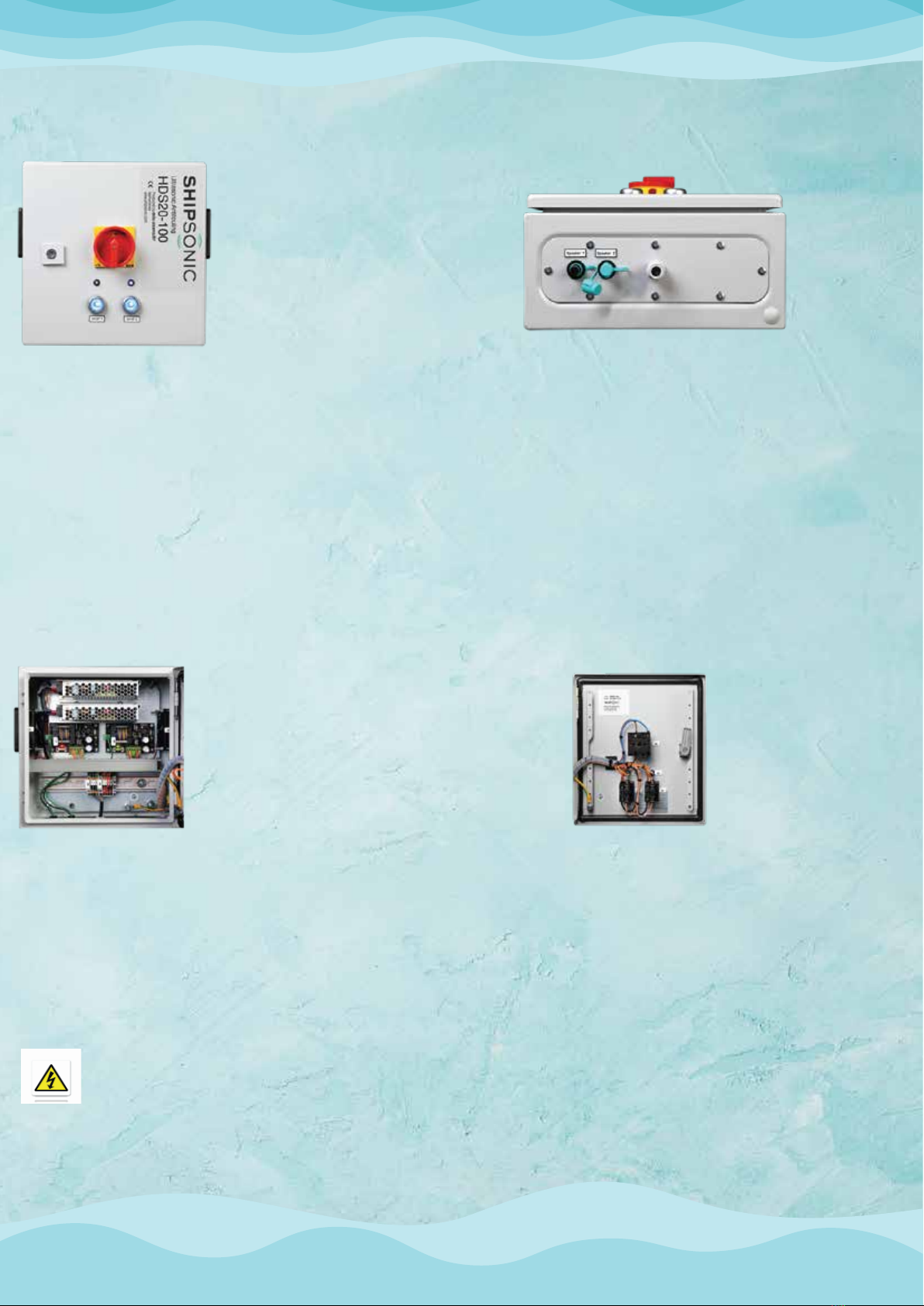
Front exterior of HDS20
The HDS series is mounted in a cabinet with
rubber door seal and safety lock with removable
key.
The red/yellow on/o emergency power switch
(110/240 AC) can be locked in the o position.
The blue signal lamp indicates the power circuit
board (PCB) actuation.
The blue illuminated push switch actuates the
PCB
Bottom exterior of HDS20
To the right the 110-240 AC power
cable inlet, and to the left the TH381
2 pole transducer connector.
Product overview inside
Interior cabinet door of HDS20
Cabinet door with seal, separate
grounding, push buttons, indica-
tor lights, power switch and
system identication sticker.
Product overview outside
Interior of HDS20
On top 2 Mean Well power supplies, below the Power Circuit Boards
(PCB). Each transducer has an individual power supply and PCB.
Each PCB has 2 2-color LED indicators; green for power on and red
for blown fuse. In the picture, the left PCB has a blown fuse (demon-
stration purposes only), the right PCB is functioning properly.
Power supplies, PCBs, activation buttons, indicator lights and trans-
ducer connectors have corresponding numbers.
WARNING:
H
igh voltage and high capacitance is present in Shipsonic HDS ultrasonic systems. Only qualified
electricians are permitted to work on this equipment.

Planning
www.mgpsltd.com
Plan the layout of your complete system. Position the control-unit such that engine room staff can
c
heck the indicator LEDs regularly. Do notlocate it too far from the box-cooler, plate-cooler intake
o
r any other object that you want to protect form fouling. Standard the transducers are equipped
w
ith 10 meter cables. Make sure the control-unit is within reach of a suitable electrical source
(earthed).
www.mgpsltd.com
System identication
Digits of the information on the identification sticker:
T
ype: HDS X0 - XXX
Wattage of transducers
Number of transducers
S
erial: HDS X0 - XXX-XX-XX
Serial number in year of manufacture
Year of manufacture
Wattage of transducers
Number of transducers
Date: day-month-year
Installation
Plan the layout of your complete system. Position the control unit such that engine room staff can
c
heck the indicator LEDs regularly. Do not locate it too far from the box- cooler, plate- cooler intake
o
r any other object that you want to protect form fouling. Standard the transducers are equipped
w
ith 10 meter cables. Make sure the control unit is within reach of a suitable electrical source
(earthed).
Installation of the control unit
Identify a suitable location for the control unit :
•
Clean and dry
•
Well ventilated
•
Ambient temperature of -10° C (14° F) to -50° C (122° F)
•
Protected from airborne particulate, moisture and dirt.
M
ount the control unit using the installation brackets supplied in a plastic bag inside the cabinet.
C
onnect the unit to a dedicated 110-240 VAC–16 ampere, single-phase outlet with grounding,
u
sing the connectors in the lower right corner of the cabinet.
I
ncoming power must be free of any power surges or spikes greater than 15% of rated voltage i.e.:
1
10 VAC with a maximum of 126 VAC
2
40 VAC with a maximum of 276 VAC
(spikes < 0.5 seconds in duration)

www.mgpsltd.com
The standard transducer cable has a length of 10 meter. In your order you might have
specied a dierent length. Conduct the transducer cable between transducer and
control unit out of harm's way, using tie-wraps as deemed necessary. Do not roll up
spare transducer cable into a tight service loop; a tightly rolled loop might start func-
tioning as a spool and interfere with the working of the transducer.
Activation
2 pin Techno IP68 connectors
Connect the control box to a 110–240 Volt power outlet if you had not already done so.
T
urn on the main power red/yellow emergency power switch. Power on the transducer through the
b
lue push button switch. The blue illumination of the push button should come on permanently.
T
he blue indicator light for the transducer should start blinking.
I
f possible check if you can hear a light ticking sound coming fromthe transducer.
Your system is now functional.
Installation of the transducer
Delta-sistems oers dierent types of transducers:
-100 Watt, 28 kHz water resistant IP63, PVC housing, direct glue or aluminum bracket installation
-100 Watt, 28 kHz water proof IP67, POM and stainless steel 316 housing, direct glue installation
-120 Watt, 20 kHz water proof IP67, POM housing, direct glue installation
Especially for clients that operate ROVs, we oer 50 Watt, 40 kHz transducers (water proof IP67,
POM and stainless steel 316 housing, direct glue installation).
You will nd the transducer installation manual -for the specic transducer type you have
chosen- attached to this manual.
Transducer cable
Connect the transducer cables to the connectors at the underside of the control unit using the IP68
connectors. It is not possible to mix up the polarity with these connectors.

www.mgpsltd.com
Schematic electrical diagram
For a detailed electrical diagram please refer to the technical documentation that you have
received separately.
Maintenance checklist
Your ultrasonic antifouling system does not need regular maintenance. Just check the
following minor items regularly:
-Check the inside of the cabinet and remove dust and particles once per month
-Check the installation of the transducer. If the transducer has come o, re-install applying
the steps under 'Installation of the transducer' again.
Troubleshooting
Step 1: The blue LED does not blink
If the transducer is not working properly, the blue indicator light on the cabinet door will stop
blinking. If this happens, open the cabinet, the PCB will probably have the its red LED on.
Then switch o the transducer and remove 240 VAC from the cabinet. Now disconnect the
transducer from the control cabinet.
Step 2: The fuse
Check the fuse of the PCB. If it is blown, replace it with a T6A, reapply 240 AC and check the
functioning of the PCB through the blue blinking light on the cabinet door. If it does start
blinking normally, the PCB is ne and the problem is the transducer. Proceed to step 3. If the
PCB does not start blinking normally (the fuse might trip again), proceed to step 4.
Step 3: Check the transducer
Using a multi-meter, check resistance between pin 1 and pin 2 on the male (cable-end) IP68
connector of the transducer. Resistance should be 1. If it is not 1, there is a short circuit in the
transducer or in the wire. Check the wire for damages, and if possible, take out the damaged
part. If the wire is not damaged, replace the transducer with cable with a new one. The inner
parts of the transducer are not serviceable. If wire and transducer are in order (resistance
between pole 1 and pole 2 is 1), proceed to step 4.
Step 4: Replace the PCB
If the fuse trips again and the transducer has been checked as described under step 3, replace
the entire PCB. On the PCB, pull o the green connectors (do not remove the wires from the
green connector itself). Loosen the 4 screws on the corners of the PCB and pull out the PCB.
Install the new PCB by applying the steps in reverse order. Close the cabinet and power on

www.mgpsltd.com
17 Western Cresent Kilbirnie Ayrshire United Kindom KA25 5JE
Technical support and after sales service
Technical support is available through email or directly by telephone from your local dealer or from Shipsonic.
When calling, please be prepared to provide the information on the identication sticker on the inside of the
cabinet door of the control-unit. Requests for parts can also be placed by phone or sent by email to your local
agent or Shipsonic.
If a system needs to be returned for repair, contact your local agent or Shipsonic directly. We will arrange the
repair and/or eventually the exchange of the system. Shipsonic pays for all repairs/replacements within the
warranty period (1 year). Outside that period, your agent and/or Shipsonic will decide on a case by case basis
what to do and whom will bear the costs.
For any additional information contact your local agent :
Marine Growth Prevention Specialists Ltd
info@mgpsltd.com
+44 7539 432763 / +44 7411 273640
CE certication
All our products are in conformity with the essential requirements of directives 2004/108/EC (Electromagnetic
Compatibility) 2011/65/EC (RoHS Directive) and 2006/95/EC (Low Voltage Directive) and their subsequent
amendments of the European Parliament and Council.
CE - test done in accordance with the company: “Globus Benelux Hattem”The Netherlands:
CE - test ultrasonic anti fouling systems, under the following test norm:
NEN-EN IEC 61000-6
ELECTROMAGNETIC COMPATIBILITY (EMC)-PART 6-4
GENERIC STANDARDS – EMMISION STANDARDS FOR INDUSTRIAL ENVIRONMENTS:
(IEC610000-6-4:2006/A1;2010,IDT)
All modications reserved
Contacts
+44 7539 432763 +44 7411 273640
This manual suits for next models
1
Table of contents
Popular Protection Device manuals by other brands


Victron energy
Victron energy Smart BatteryProtect manual

nvent
nvent ERICO System 3000 Installation, operation and maintenance manual

Ditek
Ditek DTK-DRP16 user guide

Verbatim
Verbatim Endpoint Protector Basic user guide

SNOWSOUND
SNOWSOUND BOTANICA 513-A/L0 manual

BECKWITH ELECTRIC
BECKWITH ELECTRIC M-3425A Instruction book