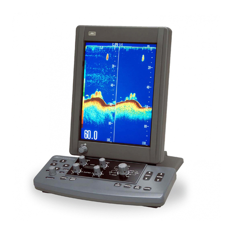
JRC JFV-130HP Series User manual

COLOR ECHO SOUNDER
JFV-130HP SERIES
JFV-130HP
JFV-131HP
INSTALLATION MANUAL
H-7ZPBS6002A

1
General Information
This installation manual describes the installation, maintenance and inspection proce-
dures for the JFV-130HP series. Prior to the installation, users are requested to read
this manual well and familiarize with its contents so that an optimum function may be
derived from the JFV-130HP.
Note that the grounding work is indispensable to prevent electric shock hazards as well
as to ensure the intended function of the set. Don’t try to ignore the grounding work.
For the operation of the set, refer to the Instruction Manual.

2
Before You Begin
Symbols Used In This Manual
Related Symbols Marks
In this manual, and on the equipment, we use several warning signs to call your attention to impor-
tant to items that, if not handled correctly, could present danger to yourself or property. These
warning note classifications are as described below.
Please be fully aware of the importance of these items before using this manual.
Examples of Related Symbol Marks Used in this Manual and on the Unit
Warning Label
You can see the warning label on the top of the unit.
Do you attempt to remove the warning label from the unit or impair or modify it.
Each marks is intended to alert the user to the presence of prohibited
activity. The picture/word in/beside each mark alerts you to operations
that are prohibited
WARNING
CAUTION
Hot Surface
Prohibition
Each △mark is intended to alert the user to the presence of precautions
including danger and warning items. The picture in each △mark alerts
you to operations that should be carefully performed.
Prohibitions
disassembly
Instruction
Each ●mark is intended to alert the user to the presence of necessary
instructions. The picture in each ●mark alerts you to operations that
must be performed..
Indicates warning items that, if ignored, may
result in serious personal injury or even death.
Indicated cautionary items that, if ignored, may
result in personal injury or physical damage.

3
Usage Hints
When installing this set, be sure to connect the
grounding wire to the grounding terminal of the
set. Otherwise, an electric shock can result
when a failure or leakage occurred on the set.
Do not damage, break or modify the power
cord.
Placing a heavy load, heating, pulling or for-
cibly bending the cord can damage it result-
ing in a fire or an electric shock.
Do not use this set at a voltage other than the
supply voltage stated on the set. Otherwise,
a fire, an electric shock or system failure can
result.
Do not touch inside the set with wet hands.
When your hands are wet, don’t try to connect
or disconnect the power cord or touch the
switches. Otherwise, an electric shock can
result.
WARNING

4
When cleaning the surface, do not use any
organic solvent such as thinner or benzene.
Otherwise, the painting on the surface may be
damaged.
For cleaning the surface, remove the dust, then
wipe with clean dry cloth.
Do not try to make transmission when the
transducer is not connected, otherwise, the
transducer may fail.
Do not try to make transmission when the
transducer is not in water. Otherwise, the
transducer or transmitter may fail.
Do not bring the set in a cooled state suddenly
into a warm room.
A high voltage may leak due to dew condensa-
tion resulting in a failure. In this case, use the
set after leaving it alone for 30 minutes.
When removing the power cord, be sure to re-
move the power cord terminal correctly.
Pulling the power cord can damage it resulting
in a fire or an electric shock.
CAUTION
No!
Not connected
Power
on
Trans-
mit
benzene
Thinner

5
General Information ・・・・・・・・・・・・・・・・・・・・・・・・・・・・・・・・・・・・・・・・・・・・・・・・・・・・・・・・・・・・・・・・ 1
Before you Begin・・・・・・・・・・・・・・・・・・・・・・・・・・・・・・・・・・・・・・・・・・・・・・・・・・・・・・・・・・・・・・・・・・・ 2
Usage Hints ・・・・・・・・・・・・・・・・・・・・・・・・・・・・・・・・・・・・・・・・・・・・・・・・・・・・・・・・・・・・・・・・・・・・・・・ 3
1 Configuration
1.1 List of Models・・・・・・・・・・・・・・・・・・・・・・・・・・・・・・・・・・・・・・・・・・・・・・・・・・・・・・・・・ 6
1.2 List of Components・・・・・・・・・・・・・・・・・・・・・・・・・・・・・・・・・・・・・・・・・・・・・・・・・・・・ 7
2 Installation
2.1 Mounting of Echo Sounder ・・・・・・・・・・・・・・・・・・・・・・・・・・・・・・・・・・・・・・・・・・・・・ 9
2.2 Connection Between Components・・・・・・・・・・・・・・・・・・・・・・・・・・・・・・・・・・・・・・ 11
2.3 Connecting the Power Supply and Transducer Connectors・・・・・・・・・・・・・・・・・ 12
2.4 Transducer Installation Procedure ・・・・・・・・・・・・・・・・・・・・・・・・・・・・・・・・・・・・・・ 14
2.5 List of Transducers Equipped ・・・・・・・・・・・・・・・・・・・・・・・・・・・・・・・・・・・・・・・・・・ 20
2.6 Grounding Work ・・・・・・・・・・・・・・・・・・・・・・・・・・・・・・・・・・・・・・・・・・・・・・・・・・・・・ 21
2.7 Connecting Optional Equipment・・・・・・・・・・・・・・・・・・・・・・・・・・・・・・・・・・・・・・・・ 22
2.8 Connecting the Water Temperature Sensor (Thermistor type) ・・・・・・・・・・・・・・ 23
2.9 Connecting External Equipment
2.9.1 Output of Sea Bottom Depth・・・・・・・・・・・・・・・・・・・・・・・・・・・・・・・・・ 25
2.9.2 Output of Cursor Position Water Depth・・・・・・・・・・・・・・・・・・・・・・・・ 25
2.9.3 Input of Water Temperature Data (NMEA type sensor) ・・・・・・・・・・ 26
2.9.4 Connection to Squid Fishing Gear ・・・・・・・・・・・・・・・・・・・・・・・・・・・・ 27
2.10 Connecting the Remote Controller (NCH-466E) ・・・・・・・・・・・・・・・・・・・・・・・・・ 28
2.11 Connecting the S.Split Signal (Telefinder)
2.11.1 Output to the Telefinder・・・・・・・・・・・・・・・・・・・・・・・・・・・・・・・・・・・・ 28
2.11.2 Input of External S.Slip Signal ・・・・・・・・・・・・・・・・・・・・・・・・・・・・・・ 29
2.11.3 Output of Events・・・・・・・・・・・・・・・・・・・・・・・・・・・・・・・・・・・・・・・・・・ 31
2.12 Actions Required After the Installation ・・・・・・・・・・・・・・・・・・・・・・・・・・・・・・・・・ 33
2.13 Actions Taken for Noise Trouble ・・・・・・・・・・・・・・・・・・・・・・・・・・・・・・・・・・・・・・ 33
3 Adjustment After Installation
3.1 Adjustment of Frequency・・・・・・・・・・・・・・・・・・・・・・・・・・・・・・・・・・・・・・・・・・・・・・ 35
3.2 Fishing Method and Corresponding Setup ・・・・・・・・・・・・・・・・・・・・・・・・・・・・・・・ 36
3.3 Setup Changes Needed When Switched from Our Competitors・・・・・・・・・・・・・ 36
4 Frequency Change
4.1 Case of 7PCBS7016A
4.1.1 Switching to Single Frequency ・・・・・・・・・・・・・・・・・・・・・・・・・・・・・・・ 37
4.1.2 Switching to Dual Frequency・・・・・・・・・・・・・・・・・・・・・・・・・・・・・・・・・ 39
4.2 Case of 7PCBS7016C
4.2.1 Switching to Single Frequency ・・・・・・・・・・・・・・・・・・・・・・・・・・・・・・・ 42
4.2.2 Switching to Dual Frequency・・・・・・・・・・・・・・・・・・・・・・・・・・・・・・・・・ 43
4.3 Implementing the Master Reset ・・・・・・・・・・・・・・・・・・・・・・・・・・・・・・・・・・・・・・・・ 46
5 Appendix
5.1 Parts List and Assembly Drawing・・・・・・・・・・・・・・・・・・・・・・・・・・・・・・・・・・・・・・・ 49
5.2 System Setting as Delivered・・・・・・・・・・・・・・・・・・・・・・・・・・・・・・・・・・・・・・・・・・・ 53
6
1 Configuration
1.1 List of Models
Digit 1 2 3 4 5 6 7 8 9 10 11 12 13 14
JFV−13□HP □□□□□
① ② ③ ④ ⑤
① Model identification
0: JFV-130HP 3kw with vertical display.
1: JFV-131HP 3kw with horizontal display.
② Characters used on the display panel
J: Japanese
E: English
③ Selection of piezoelectric transducer
Frequency Output 3 kW
Code
200 kHz K
75 kHz L
50 kHz M
38 kHz 4
28 kHz N
Others W
200 kHz in the single frequency mode is indicated by an alphabet code
followed by an asterisks (*). See below.
200 kHz:K* Other frequencies are indicated as below.
75 kHz,50 kHz,38 kHz、28 kHz:*L、*M、*4、*N
④ Identification of input voltage
B: 24/32 VDC
J: 100/220 VAC
⑤ Customized specification
Individual customized specification is indicated by a corresponding code.
Examples
JFV-13OHPJKMB: 3kw vertical display type, for the frequency of 200 to 50 kHz,
fabricated per DC specification and employing the Japanese lan-
guage for the display panel characters.
JFV-131HE*MJ: 3kw horizontal display type, for the single frequency of 50 kHz,
fabricated per AC specification and employing the English lan-
guage for the display panel characters.

7
1.2 List of Components
Standard Components
Description Model No. Quantity Remarks
Echo sounder Vertical
display
Horizontal
display
JFV‑130HP
JFV‑131HP
1Any one of the two.
Transducer Depends on the frequency and
mounting method. 1 or 2
Spares 7ZXBS0004 2 pieces of fuse.
Power cable CFQ-8383-3 13.0 meters long with4P connec-
tors.
Vinyl cover MPXP30911 1
Instruction
manual Japanese
English
7ZPBS1502
7ZPBS2503 1Any one of the two.
Operation
card Japanese
English
7ZPBS7504
7ZPBS7505 1Any one of the two.
Washer 4M6Accessories
Tapping screws 4M6×25 mm
Optional Accessories
Description Model No. Quantity Remarks
Filter MPOL30152
Hood MTT303329
Interface mounting
parts 7ZZBS0001 Two connectors
Remote
control
switch
Japanese
English
NCH-466J
NCH-466E With 4 meters long cable.
Rectifier NBA-3263 Input 100 VAC and output 24 VDC.

8
2 Installation
When installing the system, make sure that the grounding cable is
connected to the grounding terminal. Otherwise, an electric
shock can result when failure or leakage developed on the sys-
tem.
Do not install the set in a place that exposes the CRT to direct sun
for a long time or a place whose environmental temperature can
reach 50
°
C or above. Otherwise, fire hazards or system failure
can result from such operating environment.
Do not install the set on an unstable place such as shaky or in-
clined bench. Otherwise, personal injuries can result from the
fallen or collapse set.
Environment of the set must be free of magnetism field. Installing
the set near to a speaker or transformer can cause misalignment of
colors on the CRT.
Do not close the ventilation port of the set. Otherwise, fire haz-
ards or system failure can result from the heated set.
Reasonable care must be exercised for the routing of piezoelectric
transducer, power cable and grounding cable. Otherwise, the
echo sounder can adversely effect other equipment or vice versa.
When the echo sounder installation is complete, turn on power for
all other equipment to make sure that they are free of troubles.
CAUTION

9
2.1 Mounting of Echo Sounder
(1) Mounting location
1. The transducer cable tends to pick up generate noise, thus the echo sounder must
be installed in a location that can prevent interference between the cable and a co-
axial cable on a radio equipment.
2. The echo sounder must not be installed near a DSB or amateur radio equipment.
Side View of Mounted Echo Sounder
Maintenance space
Rear side cable is
connected.
Maintenance
space
(Unit: mm)
↑↑ ↑↑
Tapping screw hole Tapping screw hole
(φ6) (φ6)

10
(2) Mounting procedure
1. Loosen two main body fixing bolts situated at lower front side of the main body,
then remove the mounting plate.
2. Drill four tapping screw holes (φ4 mm) in the main body mounting location.
3. Using the tapping screws attached to the main body, fix the mounting plate to the
desk.
4. Using the two bolts already being removed (in the step 1 above), fix the main body
to the mounting plate.
Top View of Mounted Echo Sounder
8 –6 mounting
hole for an M6 tap-
ping screw (four
screws in total)
Any one of the
two holes shall
be used.
Maintenance space
(Unit: mm)

11
2.2 Connection Between Components
Component Connection Diagram

12
2.3 PConnecting the Power Supply and Transducer Connectors
(1) Connecting the Power Cables
1. Use CFQ-8383-8 for the power cable.
2. Connect the power cables as indicated below:
3. When the installation requires to extend the power cable, the cable used must be
DPYC-2.0 or above so that voltage on the connector when conducted may not go
20V or less.
4. At powering on, 8A current is conducted to the JFV-130HP for two seconds. Cur-
rent capacity of a circuit breaker, if any, must be suitable for the above current.
5. If you connect the power cable to the power terminal used on the radio equipment,
noise can be generated on the equipment.
(2) Power Cable Connecting Procedure For AC specification
1. Connect NBA-3263 rectifier to the AC power supply, then connect the power cable
to the rectifier.
(3) Power Cable Wiring Procedure
1. Don't try to bundle the radio equipment coaxial cable with the echo sounder power
cable. Such practice can generate noise on the radio equipment.
(4) Transducer Cable Connecting Procedure
1. Connectors are attached to the 3 kw transducer. Connect the cables to the con-
nectors as indicated below, then solder them to the connectors.
HS21P-3 HS21P-5
transducer for a single, transducer for
dual or low frequency: dual and high frequency:
Cable Pin No. Cable Pin No.
White 1-1
Shielded 2White 2
Black 3Shielded 3
Black 4
-5
Cable Connector pin number Polarity
White 1+
Red 2+
Black 3-
Green 4-
Shielded Connector case -

13
(5) Transducer Cable Wiring Procedure
1. Don't try to bundle the transducer cable with other cables. When this cable is
routed along with another cable, 50 cm minimum space must be provided between
the them.
2. The cable on the echo sounder transducer tends to pick up or generate noise, thus
it must not be bundled with the coaxial cable on the radio equipment.
3. It is recommended to route the transducer cable through iron pipe.
Power connector
HS16P-4
Power Supply and Transducer Connectors Connection Diagram
To the transducer
Low frequency side when the
single or dual frequency mode
is selected.
(75 kHz, 50 kHz, 38 kHz and 28
kHz)
HS21P-3
High frequency side when
the dual frequency mode is
selected.

14
2.4 Transducer Installation Procedure
Installation Diagram of Dual Transducer Installation for FRP Boat

15
Installation Diagram of Dual Frequency Transducer for Iron Boat

16
Installation Diagram of Single Frequency Transducer for FRP Boat

17
Installation Diagram of Single Frequency Transducer for Iron Boat

18
Installation Diagram of Single Frequency Transducer for Iron Boat

19
Installation Diagram of Single Frequency Transducer for Iron Boat
This manual suits for next models
1
Table of contents
Other JRC Marine Equipment manuals

JRC
JRC Alphatron Marine AlphaTurn User manual

JRC
JRC JLR-7900 User manual

JRC
JRC JFV-700 Series User manual

JRC
JRC Alphatron Marine AlphaDynaPos User manual

JRC
JRC Alphatron AlphaPilot MFS User manual

JRC
JRC JFE-680 - User manual

JRC
JRC JHS-182 - User manual

JRC
JRC JMR-5400 Series User manual

JRC
JRC JFC-130 - User manual

JRC
JRC JFE-700 User manual