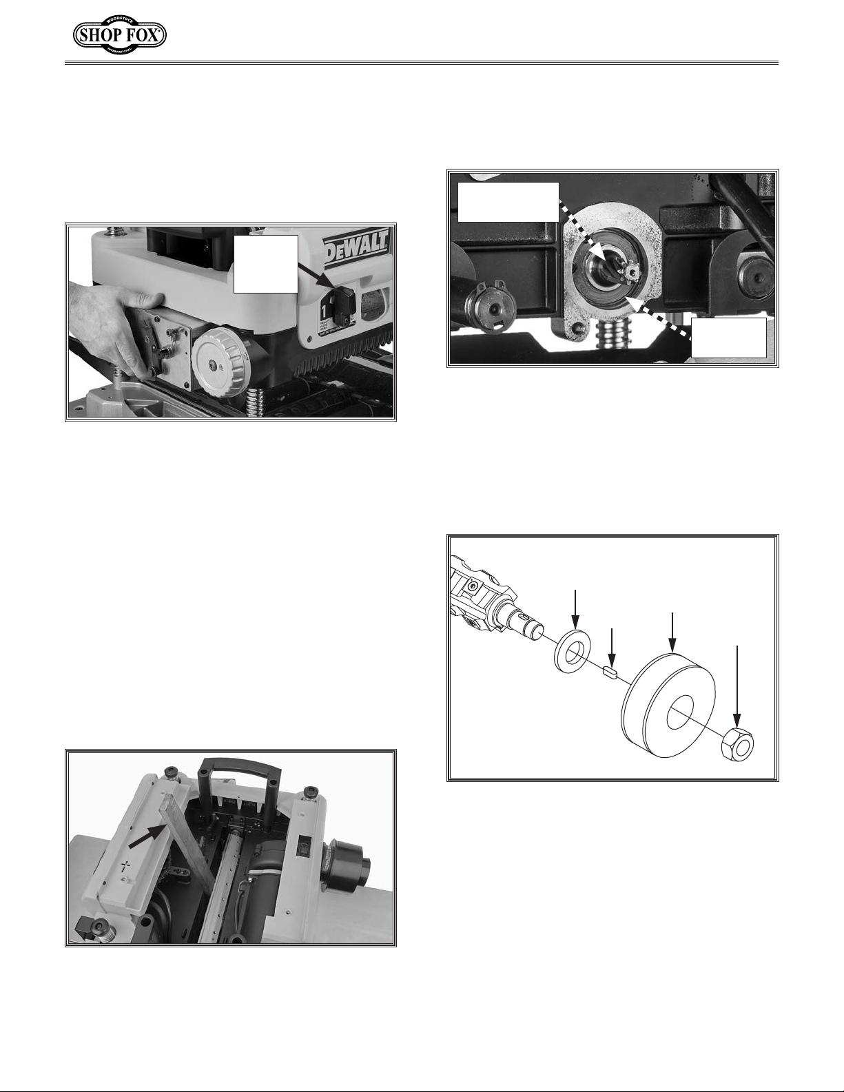
Figure 25. Rotating indexable carbide insert.
Reference Dot
-8-
D4976 13" Spiral Cutterhead Instructions
Item Needed:
Pair of Heavy Leather Gloves ...................... 1
T-Handle Torx Driver T-25 .......................... 1
T-30 Torx Driver (Included w/DW735/X) .........1
Torque Wrench 0-50in.-lb........................... 1
Clean Shop Rags.......................... As Needed
Degreaser ................................. As Needed
Light Machine Oil ........................ As Needed
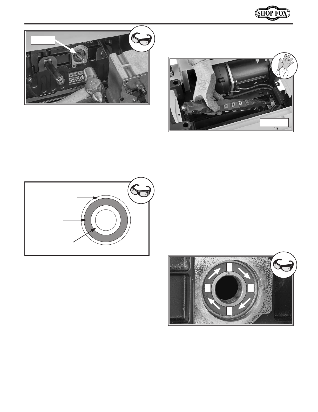
The Model D4976 13" Spiral Cutterhead is
equipped with 30 indexable carbide inserts.
Each insert can be rotated to reveal any one
of its four cutting edges. If one cutting edge
becomes dull or damaged, rotate it 90˚ to reveal
a fresh cutting edge, as shown in Figure 25.
Rotating/Replacing Indexable Inserts Note: Proper cleaning is critical to
achieving a smooth finish. Contaminants
trapped between the insert and cutterhead
will slightly raise the insert, making
noticeable marks on your workpieces the
next time you plane.
5. Lubricate Torx screw threads with a light
machine oil, wipe excess oil off threads,
and torque screw to 48-50 inch/pounds.
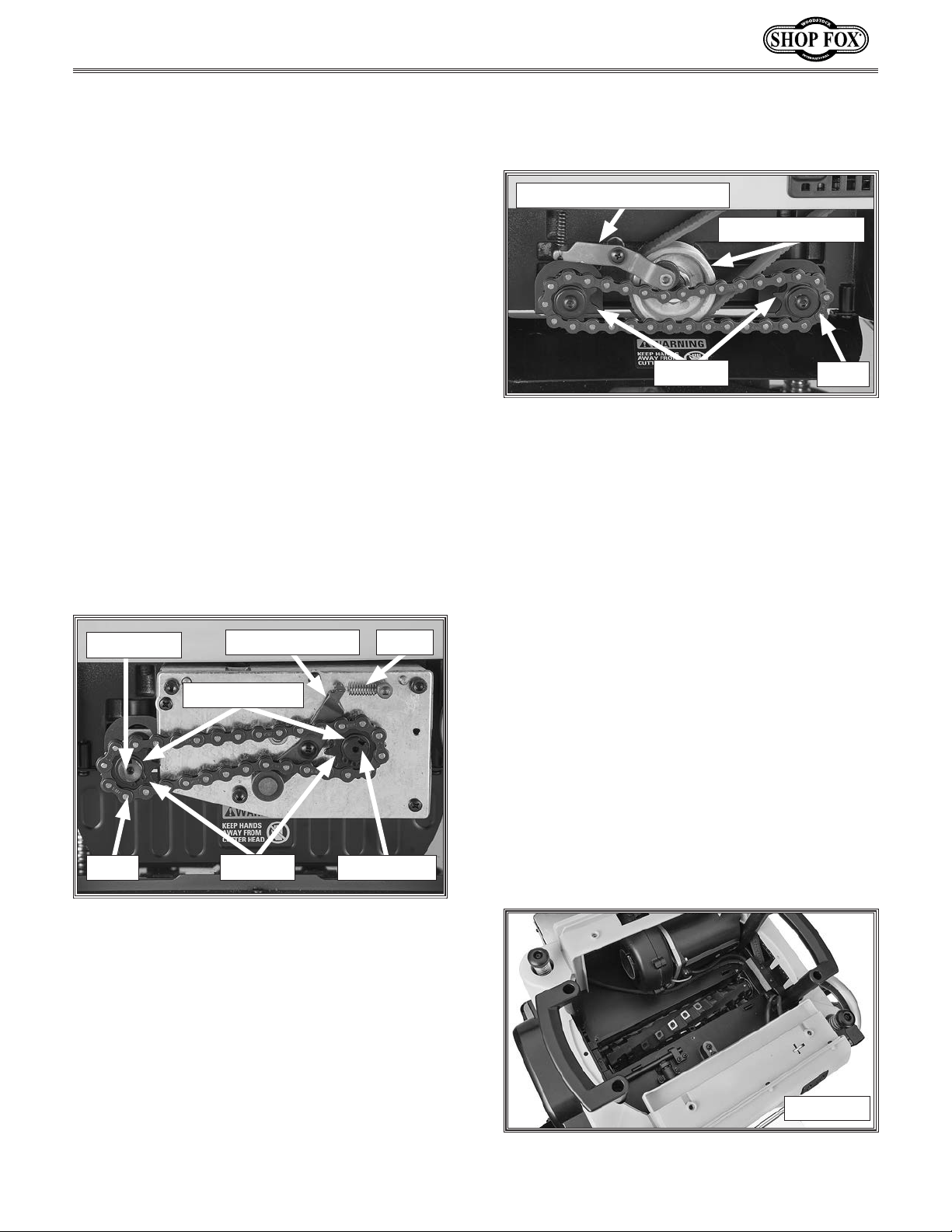
6. Return planer to its original configuration
by performing Steps 33–38 on Page 7 of
Installing Spiral Cutterhead instructions.
Accessories
D4297—Indexable Carbide Inserts (10 pack)
Replacement indexable carbide inserts for Model
D4976 13" Spiral Cutterhead.
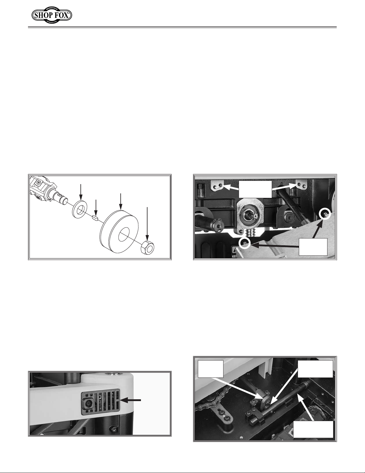
1
3
2
4
6
7
1XD4976001 SPIRAL CUTTERHEAD 13"
2XD4976002 CARBIDE INSERT 15 X 15 X 2.5MM (10PK)
3XD4976003 FLAT HD TORX SCR T-25 #10-32 X 1/2
4XD4976004 BALL BEARING 6204-2NSE
5XD4976005 T-HANDLE TORX DRIVER T-25
6XD4976006 HELICAL PINION GEAR 8T
7XD4976007 BALL BEARING 6202-2NSE
Parts Breakdown & List
Each insert has a reference dot on one corner.
As the insert is rotated, the reference dot
location can be used as an indicator of which
edges are used and which are new. When the
reference dot revolves back to its starting
position, the insert should be replaced.
To rotate or replace an insert, do these steps:
1. DISCONNECT MACHINE FROM POWER!
2. Gain access to cutterhead by performing
Steps 2–6 of Removing Existing
Cutterhead instructions.
3. Remove Torx screw and carbide insert.
4. Clean all dust and dirt off insert and
cutterhead pocket from which insert was
removed, and replace insert so a fresh,
sharp edge is facing outward.