Show Pro Industries Pro Cutter 009 User manual
SHOW PRO INDUSTRIES
P.O. Box 1235, Springtown, TX 76082 / (817)523-4055 / (817)220-5117 fax
Show Pro Industries would like to thank you for purchasing a Pro Cutter.
Every effort has been taken to provide you with a quality product designed to
provide years of trouble-free service.
Pro Cutter 009
Packing List:
control box (steel box containing electronic components)
antenna *
remote control (worn on rider's wrist)
off-side pulley
(4) heavy duty cable ties for mounting control box
installation instructions
Cow Model:
FLEX cow **
slide tube set w/snaps
kevlar cable (custom cut) & "tech" line
Flag Model:
flat braid rope (400’)
trainer flag
*Do not discard protective cap. Re-use cap to protect antenna connector when antenna is
not installed.
** A black & white banner can be added that will interchange with cow.

INSTALLATION INSTRUCTIONS:
Cow Model:
1. Mount control box: Securely attach control box on one side of arena. It
should be mounted so pulley on bottom of box is approximately 45 inches
from the ground.
2. Mount return pulley: Mount off-side return pulley on opposite side of
arena in horizontal position. It should also be mounted approximately 45
inches from the ground. See attached instructions for machines using a
cable tensioner.
3. Install kevlar cable: Have an assistant hold cable in center of arena. Take
end of cable attached to slide tube around idler pulley, across arena, around
both pulleys on bottom of control box, and back to center. Be sure the
straight slide tube slides freely on the back part of the loop. Tie
opposite end of cable to slide tube and tighten removing as much slack as
possible. Tie s knot and cut off extra cable. Keep in mind that the objective
is to form a loop with the cable. The slide tube with two snaps supports
the cow’s head, and the slide tube with one snap (slides freely on back part
of loop) supports the cow’s shoulder.
4. Install "TECH" line: The tech line is static and supports the cow’s hip. A
slide tube is pre-installed on this line. Tie one end of tech line to fence as
close to control box as possible. There should be no more than 2 –3
inches between the back part of the loop and the tech line. Tie to fence on
opposite side of arena and tighten. Installing tech line close to shoulder
line causes the cow to travel flat, stop flat, and turn around smoothly.
5. Install antenna: Remove protective cap from antenna connecter on top of
control box. Insert whip antenna into connecter, push down, and twist
clockwise approximately ¼ turn. You should feel antenna lock into
position. (To remove antenna, squeeze base and twist counter-clockwise)
6. Apply power: Plug Pro Cutter into grounded 120VAC, 3-prong outlet.
Waiting a few minutes before operating allows the climate control system
to stabilize temperatures and remove condensation. Always unplug unit
when not in use. *EURO MODELS: 240VAC/50Hz
7. Attach cow: Following the included drawing, attach cow to slide tubes on
kevlar cable and tech line.
8. Operate system: Take a minute to experiment with the system. Turn speed
dial on control box to "30". Attach remote control to your wrist, and
fingerplate on your index (pointer) finger. Using your thumb to operate
buttons, move cow end to end. Make any adjustments (tighten rope, adjust
Tech line, etc). Once comfortable with the controls, you are ready to
introduce your horse to the Pro Cutter. We recommend working at slow
speeds until both horse and rider are acclimated.
ADDITIONAL FEATURES:
* Soft-start acceleration: Progressive acceleration ramp
* Superior radio system: Better range, less interference.
* Large drive system: Heavy-duty industrial components
* Weather-tight NEMA enclosure
* Climate control system
*Dynamic braking
Thank you for choosing............
SHOW PRO INDUSTRIES
P.O. Box 1235, Springtown, TX 76082 / (817)523-4055 / (817)220-5117 fax
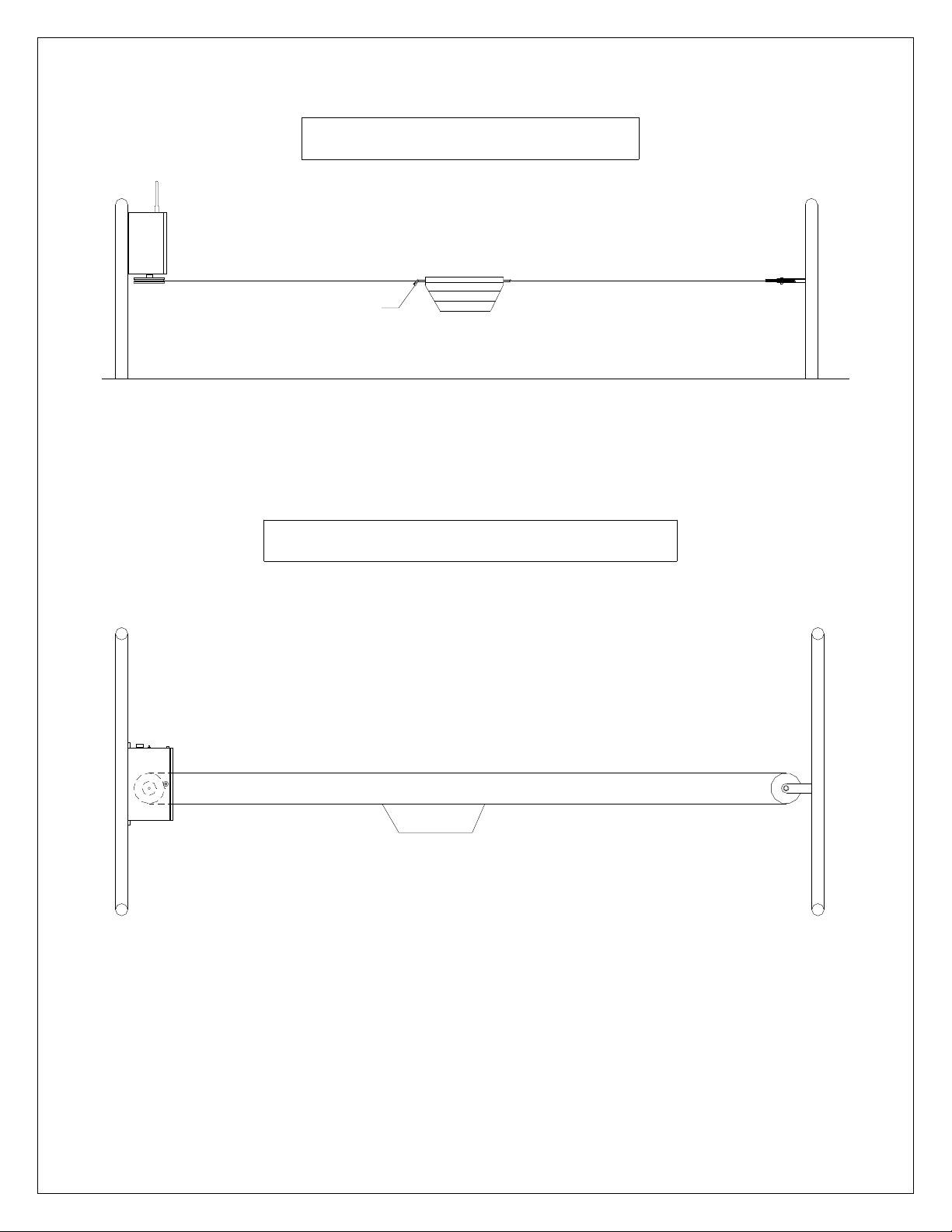
3 inch spacing
Maintain 2 to
Pro Cutter
Off-side Idler Pulley
OVERHEAD VIEW - COW MODEL
Firmly fasten static Tech line to fence
(slides freely on static Tech line)
(fastened rope through center)
Slide tube w/ 2 snaps
(slides freely on second line)
Slide tube w/ 1 snap
Slide tube w/ 1 snap

INSTALLATION INSTRUCTIONS:
Flag Model:
1. Mount control box: Securely attach control box on one side of arena. It
should be mounted so pulleys on bottom of box are approximately 45
inches from ground.
2. Mount return pulley: Mount off-side return pulley on opposite side of
arena in horizontal position. It should also be mounted approximately 45
inches from ground.
3. Install flat-braid rope: To install flat braid rope, start in center of pen.
Take one end of rope around off-side pulley, across pen, around pulley on
bottom of control box, and back to center. Tie one end of rope to left side
of flag and other end to right side of flag while removing slack. Cut extra
line.
4. Install antenna: Remove protective cap from antenna connecter on top of
control box. Insert whip antenna into connecter, push down, and twist
clockwise approximately ¼ turn. You should feel antenna lock into
position. (To remove antenna, squeeze base and twist counter-clockwise)
5. Apply power: Plug Pro Cutter into grounded 120VAC, 3-prong outlet.
Waiting a few minutes before operating allows the climate control system
to stabilize temperatures and remove condensation. Always unplug unit
when not in use. *EURO MODELS: 240VAC/50Hz
6. Operate system: Take a minute to experiment with the system. Turn speed
dial on control box to "30". Attach remote control to your wrist, and
fingerplate on your index (pointer) finger. Using your thumb to operate
buttons, move flag end to end. Make any adjustments (tighten rope, adjust
speed, etc). Once comfortable with the controls, you are ready to introduce
your horse to the Pro Cutter. We recommend working at slow speeds until
both horse and rider are acclimated.
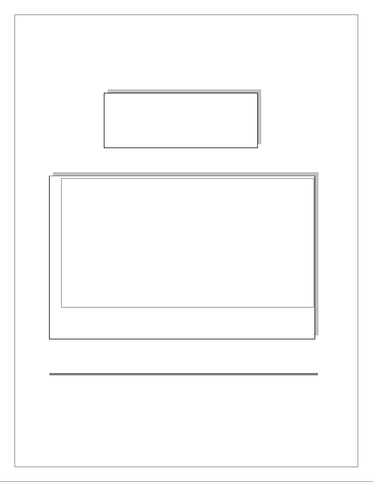
OVERHEAD VIEW - PC009
Fasten rope to
ends of flag
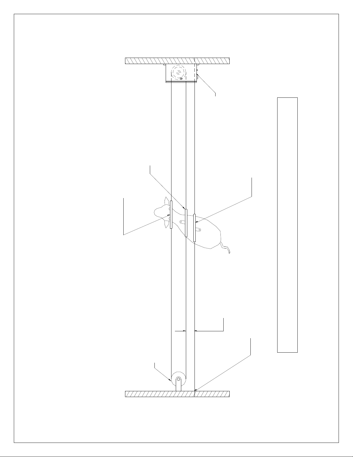
GROUND
FRONT VIEW - PC009
FLAG

FRONT VIEW
TOP VIEW
Pro Cutter Flag models with optional Cable Tensioner
GROUND
Pro Cutter
Fasten rope to
ends of flag
Cable
Tensioner
Cable
Tensioner

RETURN PULLEY
OPPOSITE SIDE OF ARENA
GROUND
46 INCHES 8.00
10.50
HOLE LOCATIONS FOR MOUNTING PC009 TO FIXED PANEL
GROUND
009
PRO CUTTER
45 INCHES

Important Safeguards:
1. Electrical enclosure (control box) should be protected with a non-metal roof or shield.
This not only protects the paint finish but also keeps rubber components (gasket, boots,
antenna, etc.) from drying out.
2. Warning: Electric shock or malfunction could occur if power cord or plug is damaged
in any way. Do not work Pro Cutter in rain –or allow cord or plug to lie in water
3. Always use properly grounded 120VAC electrical outlet.
4. Do not operate Pro Cutter if control box, or any of its components are damaged in any
way, or after malfunction.
5. Use Pro Cutter only as intended and described in literature.
6. Always unplug Pro Cutter when through working each day.
7. Do not allow flag to run into ends, or damage may occur to electronics, rope, or both.
TROUBLESHOOTING
Problem: Solution:
1. Pro Cutter will not operate Make sure there is power to
using remote control or manual machine. Check 4A fuse.
switch.
2. Pro Cutter will operate using Check battery in remote
manual switch but not remote control. Be sure antenna &
control. receptacle aren’t damaged.
3. There’s a “clicking” noise Fuse is blown.
but Pro Cutter won’t run. replace fuse (4 amp, 250 v.,
fast blow).
NOTE: The remote control, worn on the rider’s wrist, has a 9-volt battery in the plastic case
inside the pouch. The battery must be changed on a regular basis. The first sign that a battery
may be failing is when the flag starts hesitating or “missing” going one direction. The natural
tendency is to press harder on the switch, twist the cable leading to the switches, or tap the remote
control, all of which may result in damage. Avoid these conditions and replace battery at first
sign of intermittent operation. Remote control should always be stored indoors.
NOTE: The antenna, or protective cap, must be securely fastened to receptacle on top of control
box at all times. If the antenna or antenna cap is removed or damaged, water can enter the control
box resulting in severe damage to electronics. Care should be taken during installation to mount
unit in a location protected from livestock.
LIMITED WARRANTY
SHOW PRO INDUSTRIES
P.O. Box 1235, Springtown, TX 76082 / (817)523-4055 / (817)220-5117 fax
The following warranty is in lieu of all
other warranties, expressed, implied or
statutory, including but not limited to any
implied warranty of merchantability or
fitness for a particular purpose.
All new products sold by Show Pro Industries are warranted
against defects in material and workmanship for two (2) years
from the date of original purchase. During the warranty period,
Show Pro Industries will repair, or at its option replace without
charge, any SPI product (excluding normal wear items), providing
it is returned to the factory, shipping prepaid, and is proven to be
defective during the subsequent factory inspection. The warranty
period for products repaired after expiration of new product
warranty, as stated above, is limited to the repair portion and is
valid for 90 days from date of reshipment to customer. All
warranties, expressed or implied, are void if product is damaged
by accident, misuse or modification in the absence of written
authority from Show Pro Industries.
Table of contents


