Shurco 4500 HD Series User manual

Aluminum System for Grain Trailers
reverse roll
P/N 1122107 Rev. P

Shur-Co®, LLC Terms & Conditions
SHIPPING. Orders are shipped F.O.B. from the Shur-Co®, LLC sites listed be-
low. No full freight is allowed or prepaid shipment accepted unless quoted and
approved in writing prior to acceptance of the order. All shipments are made
by the most reasonable means in accordance with size and weight of order,
unless specifi ed routing instructions are furnished by the customer. Shipments
are made daily via U.P.S. and common carrier. Claims for shortages must
be made within 10 days. All claims for damages or loss in transit must be
made with the carrier. No collect calls will be accepted. To ensure delivery of
orders, we need your full street address and phone number. When you receive
your shipment, examine it carefully. Be sure all cartons listed on the delivery
sheet are accounted for. Large items may be packaged separately. If a carton
is damaged, open it and inspect the contents before signing for delivery. If
merchandise is damaged, describe damage on the delivery receipt. Failure
on your part to document damaged or missing merchandise on the delivery
receipt releases the carrier of all liability; repair or replacement will be the
customer’s responsibility.
WARRANTY. We warrant all new products are free of defects in materials and
workmanship.* This warranty is effective if products are properly installed and
used for the purpose for which they were intended and applies to the original
buyer only. Except as set forth above or in any product-specifi c warranty docu-
mentation, we make no other warranties, express or implied, including but not
limited to warranties of merchantability of fi tness for a particular use.
Returns of a product for warranty must be accompanied by a Return Merchan-
dise Authorization number (RMA#), obtained by by calling Customer Service
at 866-748-7435, and sent, with freight paid by us, to Shur-Co®, LLC, 2309
Shur-Lok St., PO Box 713, Yankton, SD 57078. All products returned without
an RMA# will be refused. When we issue the RMA#, we will also issue a call
tag to have UPS (or other freight company) pick up the product. C.O.D. returns
not accepted. We will pay no storage fees for a warranty product return prior
to pick by us or the freight company. If a warranty product return is scheduled
to be picked up by us, we will pick up the product at our earliest convenience.
If a product returned is found, in our judgement, to be defective in material
or workmanship, our obligation under this warranty is limited to the repair or
replacement of the product, which will be made by us. Repair or replacement
will be at our discretion, with replacements being made using current products
performing in the equivalent function. Labor charges, other than those incurred
at our factory, including, but not limited to, any labor to install a repaired or re-
placement product, are not covered under this warranty. All expenses associ-
ated with delivering defective products to our factory and delivering repaired or
replacement products from our factory to the owner will be paid by us.
If the product returned is found, in our judgement, to be non-warrantable, the
owner will be contacted to authorize repair work, purchase of a replacement
product or return of the product, all of which will be at the owner’s expense.
Payment authorization must be received by us before any non-warrantable
product is repaired, replaced or returned. All expenses associated with deliver-
ing the repaired non-warrantable product, a replacement product or the non-
warrantable product from our factory to the owner will be paid by the owner.
In no event will we be liable for any damages of any kind to person, product or
property, including but not limited to indirect, incidental, special, consequential
or punitive damages, or damages for loss of profi ts or revenue, even if we
have been advised of the possibility of such damages. There are no warran-
ties for used products or products that have been repaired, altered, modifi ed
or subjected to misuse, negligence or accident. We will not repair or replace
products that fail or malfunction due to ordinary wear and tear, except as ex-
pressly noted in a product-specifi c warranty. Use of non-Shur-Co®, LLC parts
in conjuction with Shur-Co®, LLC products will void this product warranty.
*Certain products have specifi c warranties that differ from this warranty, for example motors and elec-
tronics. Product-specifi c warranty documentation is available for these items. In the event of a confl ict
between this warranty and a product-specifi c warranty, the product-specifi c warranty will govern.
RETURN POLICY. All sales fi nal. See WARRANTY above for return details.
OTHER. All prices, product listings, sizes, weights and manufacturing details
are subject to change without notice. No person is authorized to modify the
foregoing conditions of sale whatsoever.
SHUR-CO®, LLC SERVICE AND DISTRIBUTION CENTERS
Corporate HQ and Outlet Store
SHUR-CO® of SOUTH DAKOTA
2309 Shur-Lok St., PO Box 713, Yankton, SD 57078
Ph 800.474.8756 | Fax 605.665.0501
SHUR-CO® of FLORIDA
3353 SE Gran Park Way, Stuart, FL 34997
Ph 800.327.8287 | Fax 772.287.0431
SHUR-CO®of IDAHO
610 N. 16th Ave., Caldwell, ID 83607
Ph 866.356.0246 | Fax 217.877.8270
SHUR-CO® of ILLINOIS
3993 E. Mueller Ave., Decatur, IL 62526
Ph 866.356.0246 | Fax 217.877.8270
SHUR-CO®of NORTH DAKOTA
1746 4th Ave. NW, West Fargo, ND 58078
Ph 877.868.4488 | Fax 701.277.1283
SHUR-CO®of OHIO
4676 Lynn Rd.
Rootstown, OH 44266
Ph 866.356.0242 | Fax 330.297.5599
SHUR-CO® of VERMILLION
1212 N. Norbeck St., Vermillion, SD
Ph 800.474.8756 | Fax 605.665.0501
SHUR-CO®of CANADA
490 Elgin St., Unit #1
Brantford, Ontario N3S 7P8
Ph 800.265.0823 | Fax 519.751.3997
SHUR-CO®UK, Ltd.
Unit 41 Rochester Airport Estates
Laker Rd., Rochester, Kent ME1 3QX
Ph +44 (0)1795.473499
Fax +44 (0)871.272.8278
For more information, log on to our website:
www.shurco.com
P/N 1122107 Rev. P
Thank you for buying this tarping system from Shur-Co®. We appreci-
ate your condence in our products. Please read and thoroughly un-
derstand this manual before installing and/or operating this system.
Pay particular attention to important safety and operating instructions,
as well as warnings and cautions. The hazard symbol is used
to alert users to potentially hazardous conditions and is followed by
caution, warning or danger messages.
Failure to READ AND FOLLOW INSTRUCTIONS could result in fail-
ure of your tarping system and/or personal injury. Your trailer require-
ments may, however, call for minor variations to these instructions.
Please inspect your tarping system periodically. Repair or replace
worn or damaged parts to your system.
QUESTIONS? CALL OUR HELP LINE:
1-866-748-7435
MON-FRI 8 AM-5 PM CENTRAL TIME
We at Shur-Co® are concerned with your safety and the safety of all
those operating this system. Therefore, we have provided safety de-
cals at various locations on your tarping system. Keep decals as clean
as possible at all times. Replace any decal that has become worn
or damaged, painted over or otherwise difcult to read. Replacement
decals are available through Shur-Co® dealers.
To prevent rust, paint all exposed metal, such as weld seams and/or
metal exposed by grinding or cutting, with corrosion-resistant paint.
4500 Series HD for Semi Grain Trailer - Reverse Roll
P/N 1122107 Rev. P
Hardware Identication.......................................................................1
Pivot Bracket Installation Front & Rear............................................2-5
Pivot Bracket Installation ....................................................................6
Front Flex Arm & Electric Motor Installation ....................................7-8
Rear Flex Arm Installation - 2" Roll Tube.......................................9-10
Rear Flex Arm Installation - 3" Roll Tube.....................................11-12
2" Roll Tube Extension Installation ..............................................13-15
3" Roll Tube Extension Installation ..............................................16-18
Electric Mounting & Wiring ..........................................................19-24
Operation..........................................................................................25
Conversion to Manual Power ...........................................................26
Electric Motor Replacement .............................................................27
Replacement Parts......................................................................28-32
1. Welder
2. Hammer
3. Center Punch or Transfer Punch
4. #3 Phillips Insert Bit
5. Air or Electric Impact Wrench (9/16” deep socket)
6. 7/16" Deep Socket
7. 3/8" Combination Wrench
8. 9/16" Combination Wrench
9. 1/2" Combination Wrench
10. 1/8" Hex Wrench Long T-Handle
11. 3/16" Hex Wrench Long T-Handle (recommended)
12. 7/32" Drill Bit
13. 5/16" Drill Bit (for 3/8” self-tapping screws)
14. 11/32" Drill Bit
15. 13/32" Drill Bit
16. 3/8" Drill
17. 1 1/8" Hole Saw
18. 1 1/2" Hole Saw
19. 2" Hole Saw (if bracket for conductor socket is not used)
20. Standard/Flathead Screwdriver
21. #2 Phillips Screwdriver
22. Utility Knife
23. Ratchet
24. Hack Saw (metal cutter)
25. Pliers
26. Snap-Ring Pliers
27. Wire Cutters
28. Grinder
29. Tape Measure
!
TOOLS REQUIRED
RUST PREVENTION
SAFETY
MESSAGE TO OWNERS TABLE OF CONTENTS
1. Always wear safety glasses during installa-
tion and operation.
2. Stay clear of moving parts.
3. No other use of this system is authorized,
except as designed.
SAFETY INSTRUCTIONS

P/N 1122107 Rev. P
1
Hardware Identication
1704946 Flanged Top Lock Nut - 5/16"
1700429 Flat Washer - 3/8"
1701455 Carriage Bolt - 5/16" x 2 1/2"
1700419 Nylon Lock Nut - 5/16"
1701045 Cap Screw - 5/16" x 3/4"
1700407 Hex Nut - 3/8"
1700434 Lock Washer - 3/8"
1118318 Spacer Washer - 1/4" x 1.81"
1201022 Cap Screw - 5/16" x 3 1/2"
1702890 Flat Washer - 1 1/4"
1701543 Nylon Lock Nut - 1/4"
1700408 Hex Nut 1/4"
1700427 Flat Washer - 1/4"
1700428 Flat Washer - 5/16"
1701580 Nylon Lock Nut - 3/8"
1704905 Hex Flanged Cap Screw #10 x 1"
1703959 Cap Screw 1/4" x 3/4"
1702926 Cap Screw - 5/16" x 7/8"
1120291 Pivot Bracket Washer
1704367 Cap Screw - #10 x 3/4"
1704905 Flanged Cap Screw - #10 x 1"
1808844 Nylon Lock Nut - #10
1700436 Lock Washer - 1/4"
1704931 Flanged Nylon Lock Nut - 5/16"
1704297 Nylon Lock Nut - 5/16"
1702668 Top Lock Nut - 3/8"
AR
S
T
U
V
W
X
Y
Z
B
C
D
E
F
G
H
J
K
L
M
N
P
Q
FF
GG
HH
JJ
KK
LL
DD
EE
AA
BB
CC
1705198 Self-Drilling Screw - 1/4" x 1"
1700403 Self-Tapping Screw - 1/4" x 3/4"
1704338 Self-Tapping Screw - 1/4" x 1"
1700398 Self-Drilling Screw - 1/4" x 3/4"
1702891 Cap Screw - 3/8" x 1 1/4"
1700400 Self-Tapping Screw - 3/8" x 1"
1704264 Cap Screw - 3/8" x 2" - Grade 8
1704943 S
houlder Bolt - 3/8" x 2
- 5/16" x 1/2" Thd
.
1704237 Carriage Bolt - 3/8" x 2"
P/N 1122107 Rev. P Pivot Bracket Installation - Vertical Trailer - Reverse Roll
NOTE: Mount brackets into support braces on trailer, if possible. If bracket cannot be mounted into support braces, reinforce
mounting area with backer plate for adequate support. Before drilling any holes, make sure ex arm has clear pathway to operate.
NOTE: Read pages 2 and 3 entirely before drilling holes.
Determine if rivets are centered or off center on front and
rear of trailer.
NOTE: Use pivot bracket washers LL only when horizontal
corrugation on trailer skin prevents bracket from contacting
trailer skin.
STEP 1: If installing pivot bracket or pivot mount bracket on
horizontally corrugated trailer skin, use brackets as
guide to mark hole locations. Mark and drill 13/32”
holes in trailer and fasten with screws P, at washers
JJ , lock washers HH , pivot bracket washers LL
and nuts AA . Locate pivot bracket washers between
pivot bracket and trailer skin as shown.
pivot
bracket
corrugated
trailer skin
locate pivot bracket
washers between
pivot bracket &
trailer skin
INSTALL BRACKETS ON HORIZONTALLY CORRUGATED TRAILERS
4”
4”
6”
rivets off
center
STEP 2: Locate rear pivot mount bracket so center of pivot lies
within shaded area shown below.
STEP 1: Locate front pivot mount bracket on driver side of
trailer so center of pivot lies within shaded area shown
below. Measure 41" down from top of cap or 43" from
top of windshield.
4"
4"
41"
4"
4"
6"
4”
4”
41”
4"
4"
6"
rivets on
center line
rivets off
center
6”
4”
4”
rivets on
center line
43"
c
l
locate center
of pivot inside
shaded area
c
l
c
l
c
l
locate center
of pivot inside
shaded area
FRONT OF TRAILER
REAR OF TRAILER
2
PAA
HH
JJ LL
P/N 1122107 Rev. P
3
Pivot Bracket Installation - Vertical Trailer - Reverse Roll - cont’d
STEP 3:
Place pivot mount
brackets on trailer as shown below.
Using brackets as guide, mark mounting hole loca-
tions.
STEP 4:
Remove rivets and mount brackets into rivet holes.
If not possible, drill 13/32" holes in trailer. Fasten with
screws
P
, at washers
JJ
, lock washers
HH
, pivot
bracket washers
LL
and nuts
AA
.
center of
trailer
c
l
c
l
c
l
c
l
RIVETS/CORRUGATION OFF CENTER
RIVETS/CORRUGATION ON CENTER
RIVETS/CORRUGATION OFF CENTER
RIVETS/CORRUGATION ON CENTER
FRONT OF TRAILER
REAR OF TRAILER
P
P
P
P
AA
AA
AA
AA
HH
HH
HH
HH
JJ
JJ
JJ
JJ
LL
LL
LL
LL

P/N 1122107 Rev. P
4
Front Bracket Installation - Sloped Trailer - Reverse Roll
NOTE: Mount brackets into support braces on trailer, if
possible. If bracket cannot be mounted into support braces,
reinforce mounting area with backer plate for adequate support.
If bracket does not sit ush with skin of trailer, install spacers
between mounting bracket and skin of trailer to assure solid
contact through support braces or backer plate.
Before drilling any holes, make sure ex arm has clear
pathway to operate.
STEP 4: Drill 13/32" holes in trailer. Fasten sloped pivot mount
bracket to trailer with screws P, at washers JJ , lock
washers HH and nuts AA .
3"
3"
41"
STEP 2: Locate sloped pivot mount bracket 41" below top of
cap, measuring vertically as shown. Do not measure
along slope of trailer.
3"
3"
41"
STEP 3: Place pivot mount brackets on trailer as shown below.
Using brackets as guide, mark mounting hole locations.
c
l
center of
trailer
43"
3"
3"
3"
6"
6"
3"
3"
3"
3"
3" 6"
6"
STEP 1: Locate sloped pivot mount bracket 41” down from top of
cap or 43” from top of windshield, measuring vertically
as shown. Do not measure along slope of trailer.
c
l
c
l
c
l
c
l
c
l
c
l
c
l
RIVETS/CORRUGATION OFF CENTER
RIVETS/CORRUGATION ON CENTER
RIVETS/CORRUGATION OFF CENTER
RIVETS/CORRUGATION ON CENTER
NOTE: Use pivot bracket washers LL only when horizontal
corrugation on trailer skin prevents bracket from contacting
trailer skin (see instructions on page 2).
NOTE: Read entire page before drilling holes. Determine if
rivets are centered or off center on front and rear of trailer.
FRONT OF TRAILER
FRONT OF TRAILER
REAR OF TRAILER
REAR OF TRAILER
P
P
P
P
AA
AA
AA
AA
JJ
JJ
JJ
JJ
HH
HH
HH
HH
LL
LL
LL
LL

P/N 1122107 Rev. P
5
Pivot Bracket Installation - Sloped Trailer - Reverse Roll
STEP 5: Place pivot brackets on pivot mount brackets ias
shown below. Fasten pivot brackets to pivot mount
brackets with screws P, at washers JJ , lock wash-
ers HH and nuts AA .
RIVETS/CORRUGATION OFF CENTER
RIVETS/CORRUGATION ON CENTER
RIVETS/CORRUGATION OFF CENTER
RIVETS/CORRUGATION ON CENTER
c
l
c
l
c
l
c
l
center of
trailer
FRONT OF TRAILER
REAR OF TRAILER
P
P
P
P
AA
AA
AA
AA
HH
HH
HH
HH
JJ
JJ
JJ
JJ
JJ
JJ
JJ
JJ
P/N 1122107 Rev. P
6
Pivot Bracket Installation - Reverse Roll
Item Part # Description
1. 1116920 Pivot Pin - 4 Spring
2. 1120361 Pivot Backer Plate - 5" x 16"
1120418 Pivot Backer Plate - 5" x 20"
3. 1121993 Sloped Pivot Mt. Bracket -
6" Standoff - 6" Wide
1121994 Sloped Pivot Mt. Bracket -
8" Standoff - 6" Wide
4. 1121992 Pivot Bracket - Sloped - 6" Wide
5. 1116919 Vertical Pivot Mount Bracket -
7-1/4" Standoff
1117031 Vertical Pivot Mount Bracket -
9-1/4" Standoff
N. 1700400 Self-Tapping Screw - 3/8" x 1"
P. 1702891 Cap Screw - 3/8" x 1-1/4"
AA. 1700407 Hex Nut - 3/8"
HH. 1700434 Lock Washer - 3/8"
JJ. 1700429 Flat Washer - 3/8"
LL. 1120291 Pivot Bracket Washer
STEP 1: Align and loosely fasten pivot bracket to pivot mount
bracket with screws P, lock washers HH , at wash-
ers JJ and nuts AA .
pivot mount
bracket
pivot
bracket
STEP 2: Align face of pivot bracket vertically and align pivot
pin parallel with top rail of trailer, then tighten screws.
align face of
pivot bracket
vertically
align pivot pin parallel
pivot pin
pivot bracket
top rail
of trailer
tighten screws
pivot
bracket
pivot pin
pivot bracket
assembly
pivot pin
STEP 3: Fasten pivot pins to pivot brackets.
1
2
3
4
1
5
keyway in pivot
pin must face
downward
keyway in pivot pin
must face downward
SLOPED TRAILER
VERTICAL TRAILER
N
N
P
P
P
P
P
P
P
AA
AA
AA
AA
AA
AA
AA
AA
AA
HH
HH
HH
HH
HH
HH
HH
HH
HH
JJ
JJ
JJ
JJ
JJ
JJ
JJ
JJ
JJ
JJ
JJ
JJ
JJ
LL
LL

P/N 1122107 Rev. P
Item Part # Description
1. 1111027 Spiral Torsion Spring
2. 1702888 External Retaining Ring - 1-1/4"
3. 1704987 SMARTwire™ - 6 Ga. Plug x
1/4" Terminal x 10'9"
4. 1704751 Harness Lock Pin - 1/4" x 7/8"
5. 1702108 Wire Clip - 3/4" ID
6. 1121414 Bellow Plate - Square Holes
7. 1121413 Bellow Plate - Round Holes
8. 1704893 Cap Plug w/Holes
E. 1700403 Self-Tapping Screw - 1/4" x 3/4"
F. 1700398 Self-Drilling Screw - 1/4" x 3/4"
L. 1701455 Carriage Bolt - 5/16" x 2-1/2"
V. 1700408 Hex Nut - 1/4"
AA. 1704931 Flanged Nylon Lock Nut - 5/16"
DD. 1700436 Lock Washer - 1/4"
EE. 1700427 Flat Washer - 1/4"
FF. 1702890 Flat Washer - 1 1/4"
KK. 1118318 Spacer Washer - 1/4" x 1.28"
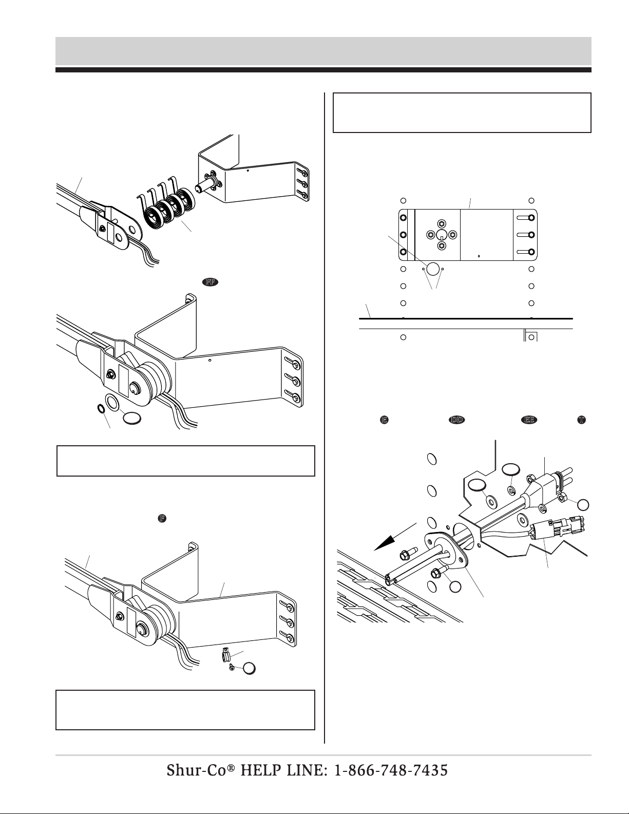
7
Front Flex Arm & Electric Motor Installation - Reverse Roll
pivot mount
bracket assembly
2
1
STEP 1: Assemble spacer washers KK onto pivot pin.
pivot pin
4
3
5
7
6
8
bellow plate
w/round holes
lower flex arm
flex arm
assembly
w/motor
STEP 2: Align holes in bellow, end
plates and bellow plates
with holes in lower ex arm
assembly as shown. Fasten
with carriage bolts L and lock
nuts X.
bellow plate
w/square holes
NOTE: Do not remove cable tie
from front ex arm and motor
assembly until installation is
complete. See step 9.
WARNING
Do not stand or climb on flex arm. Standing or climb-
ing on flex arm could result in fall/impact causing
serious injury or death.
!
X
E
F
L
L
V
AA
DD
EE
FF
KK
KK
P/N 1122107 Rev. P
8
Front Flex Arm & Motor Installation - Reverse Roll - cont’d
NOTE: Motor assembly on upper ex arm must face toward
trailer as shown.
STEP 7: Align wire plate assembly with 1 1/2" hole. Using
wiring hole as guide, mark and drill two 7/32" holes
as shown.
STEP 6: Measure 11" horizontally from center line of trailer and
1" down from lower edge of pivot bracket. Mark and
drill 1 1/2" hole through trailer skin.
drill
1 1/2"
hole
catwalk drill two
7/32" holes
pivot bracket
STEP 8:
Fasten wire plate assembly to front of trailer with screws
E
, lock washers
DD
, at washers
EE
and nuts
T
.
NOTE: Wire lengths are predetermined. Before installing
SMARTwire™ components, review and conrm wire routing
so wires reach components with ample room for
connection.
STEP 5: Route 6-ga. wire from ex arm through trailer skin.
Fasten wire to pivot bracket with wire clip and self-
drilling screw F in location shown.
NOTE: Fasten wire clip with self-drilling screw on opposite
side of pivot bracket from ex arm to prevent wire from being
pinched during operation.
flex arm
pivot bracket
wire clip
STEP 4: Secure with at washer FF and retaining ring.
retaining ring
STEP 3: Assemble spiral torsion springs and lower ex arm
onto pivot pin. Hook springs over spacer tube.
spiral torsion springs
lower flex arm
smartwire™ plug
E
T
to motor/arm
encoder wire
wiring plate assembly
STEP 9: Remove cable tie from front arm/motor assembly
before operating system.
F
DD
EE
FF

P/N 1122107 Rev. P
9
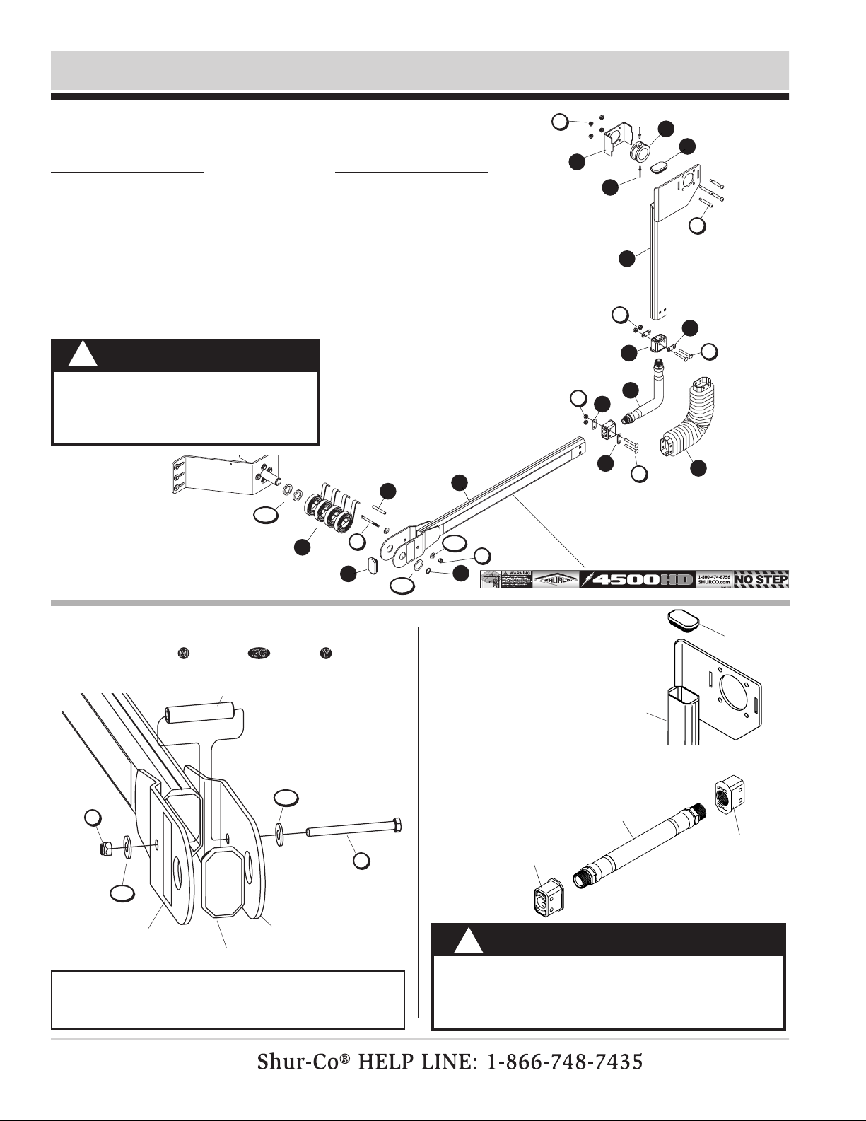
Rear Flex Arm Installation - 2" Roll Tube - Reverse Roll
STEP 1: Install cap plug on lower ex arm. Fasten spacer tube
into spring support bracket on lower ex arm with
screw M, two at washers GG and nylon lock nut Z.
spring support bracket
on lower flex arm
NOTE: Insert cap screw through ex arm so head of screw
is on inside of assembly (towards trailer). Warning label must
be in plain view on outside of assembly.
cap plug
spacer tube
STEP 2: Install cap plug on
rear upper ex arm.
cap plug
upper flex arm
STEP 3: Thread end ttings onto both ends
of ex arm joint. Tighten so end
ttings are parallel.
flex arm joint
end
fitting
end fitting
1
2
3
4
5
6
7
8
9
10
11
12
13
3
WARNING
Flex arms are under tension while torsion springs are
engaged. Use caution while assembling and disas-
sembling arms. Failure to read and follow instructions
could result in serious injury or death.
!
Item Part # Description
1. 1704942 Rear Arm Bearing Ring
2. 1121430 Bearing Mount Box
3. 1704892 Cap Plug
4. 1121281 Upper Flex Arm - Bearing - RR
5. 1121413 Bellow Plate - Round Holes
6. 1121414 Bellow Plate - Square Holes
7. 1703873 Flex Arm Joint
8. 1704775 Bellow - HD Series Arm
9. 1704891 End Fitting
10. 1122000 Lower Flex Arm w/Warning Decals
11. 1702888 Retaining Ring - 1-1/4"
12. 1117033 Spacer Tube - .35" x 2-5/8"
14
Item Part # Description
13. 1111027 Spiral Torsion Spring
14. 1706103 Blind Rivet - 3/16"
L. 1701455 Carriage Bolt - 5/16" x 2-1/2"
S. 1704943 Shoulder Bolt - 3/8" x 2" -
5/16" x 1/2" Thd.
M. 1201022 Cap Screw - 5/16" x 3-1/2"
X. 1704931 Flanged Nylon Lock Nut - 5/16"
Y. 1700419 Nylon Lock Nut - 5/16"
FF. 1702890 Flat Washer - 1-1/4"
GG. 1700428 Flat Washer - 5/16"
KK. 1118318 Spacer Washer - 1/4" x 1.28"
WARNING
Do not stand or climb on flex arm. Standing or climb-
ing on flex arm could result in fall/impact causing
serious injury or death.
!
S
X
X
M
M
Y
Y
L
FF
KK
GG
GG
GG

P/N 1122107 Rev. P
10
Rear Flex Arm Installation - 2" Roll Tube - Reverse Roll - cont’d
STEP 8: Secure with at washer FF and retaining ring.
retaining
ring
STEP 10: Insert roll tube through bearing mount box, bearing
ring and upper ex arm bearing plate, aligning end of
splined shaft 5" past bearing plate as shown.
Fasten
with
shoulder bolts
S
and nuts
X
as shown, anchoring
bearing ring between bolts.
upper flex arm
flex arm joint
bellow
NOTE: Bracket on upper ex
arm must face toward outside
of trailer as shown above.
bearing
mount box
upper flex arm
bearing plate
bearing
ring
STEP 4: Insert ex arm joint into upper ex arm and slide
bellow over ex arm joint. Align holes in upper ex
arm, bellow plates, ex arm joint and bellow. Fasten
with carriage bolts
L
and lock nuts
X
.
STEP 5:
Insert lower end tting into lower ex arm assembly
with end of bellow over outside of arm. Align holes in
lower ex arm assembly, bellow plates, end tting and
bellow. Fasten with carriage bolts
L
and lock nuts
X
.
bellow plate
w/square hole
bellow plate
w/round hole
upper flex
arm assembly
bellow plate
w/round holes
lower flex
arm assembly
STEP 6: Assemble spacer washers KK onto pivot pin.
pivot pin
STEP 7: Assemble spiral torsion springs and lower ex arm onto
pivot pin. Hook springs over spacer tube.
pivot pin
lower
flex arm
spiral torsion
springs
roll
tube
5"
STEP 9: Roll tarp closed over box
with roll tube hanging be-
low latchplate. Remove
crank assembly and U-
clamps from roll tube.
deburr roll tube
if needed before
sliding through
bearing mount
box & ring
NOTE: Remove any existing returns.
Do not leave unattended until ex
arm is securely fastened to roll tube.
bellow plate
w/square holes
rivets to be
added later
S
X
X
X
L
L
FF
KK
P/N 1122107 Rev. P
11
Rear Flex Arm Installation - 3" Roll Tube - Standard Roll
STEP 1: Install cap plug on lower ex arm. Fasten spacer
tube into spring support bracket on lower ex arm
with screw M, washers GG and nut Y.
Item Part # Description
1. 1705160 Rear Arm Bearing Ring - 3"
2. 1123248 Bearing Mount Box - 3"
3. 1704892 Cap Plug
4. 1124958 Upper Flex Arm - Bearing - 3" - RR
5. 1121413 Bellow Plate - Round Holes
6. 1121414 Bellow Plate - Square Holes
7. 1703873 Flex Arm Joint
8. 1704775 Bellow - HD Series Arm
9. 1704891 End Fitting
10. 1121999 Lower Flex Arm w/Warning Decals
11. 1702888 Retaining Ring - 1-1/4" 6
2
3
1
5
12
7
8
10
spacer tube
11
spring support
bracket on lower
flex arm
NOTE: Insert cap screw through ex arm so head of screw
is on inside of assembly (towards trailer). Warning label must
be in plain view on outside of assembly.
4
3
warning decal
cap plug
6
13
9
STEP 2: Install cap plug on
rear upper ex arm. cap plug
upper flex arm
STEP 3: Fully thread end ttings onto both ends of ex arm
joint. Tighten so end ttings are parallel.
flex arm
joint
end fitting
end fitting
WARNING
Flex arms are under tension while torsion springs are
engaged. Use caution while assembling and disas-
sembling arms. Failure to read and follow instructions
could result in serious injury or death.
!
14
Item Part # Description
12. 1117033 Spacer Tube - .35" x 2-5/8"
13. 1111027 Spiral Torsion Spring
14. 1706103 Blind Rivet - 3/16"
L. 1701455 Carriage Bolt - 5/16" x 2-1/2"
S. 1704943 Shoulder Bolt - 3/8" x 2" -
5/16" x 1/2" Thd.
M. 1201022 Cap Screw - 5/16" x 3-1/2"
X. 1704931 Flanged Nylon Lock Nut - 5/16"
Y. 1700419 Nylon Lock Nut - 5/16"
FF. 1702890 Flat Washer - 1-1/4"
GG. 1700428 Flat Washer - 5/16"
KK. 1118318 Spacer Washer - 1/4" x 1.28"
WARNING
Do not stand or climb on flex arm.
Standing or climbing on flex arm
could result in fall/impact causing
serious injury or death.
!
S
X
X
X
M
M
Y
Y
L
L
FF
KK
GG
G
GG

P/N 1122107 Rev. P Rear Flex Arm Installation - 3" Roll Tube - Standard Roll - cont'd
upper flex arm
STEP 9: Roll tarp closed over box
with roll tube hanging be-
low latchplate. Remove
crank assembly and U-
clamps from roll tube.
flex arm joint
bellow
STEP 8: Secure with washer FF and retaining ring.
retaining
ring
NOTE: Bracket on upper ex
arm must face toward outside
of trailer as shown above.
deburr roll tube
if needed before
sliding through
bearing mount
box & ring
NOTE: Remove any existing returns,
such as cable return, bungee return, etc.
Do not leave unattended until ex arm is
securely fastened to roll tube extension.
STEP 4: Insert ex arm joint into upper ex arm and slide
bellow over ex arm joint. Align holes in upper ex
arm, bellow plates, ex arm joint and bellow. Fasten
with bolts
L
and anged nuts
X
.
bellow plate
w/square hole
bellow plate
w/round hole
upper flex
arm assembly
bellow
plates
lower flex
arm assembly
STEP 6: Assemble spacer
washers KK
onto pivot pin.
STEP 7: Assemble spiral torsion springs and lower ex arm
onto pivot pin. Hook springs over spacer tube.
pivot pin
pivot pin
lower
flex
arm
spiral torsion
springs
STEP 5: Insert lower end tting into lower ex arm assembly
with end of bellow over outside of arm. Align holes
in lower ex arm assembly, bellow plates, end tting
and bellow. Fasten with bolts L and anged nuts X.
STEP 10: Insert roll tube through bearing mount box, bearing
ring and upper ex arm bearing plate, aligning end of
splined shaft 5" past bearing plate as shown.
Fasten
with
bolts
S
and nuts
X
as shown, anchoring bearing
ring between bolts.
bearing
mount box
upper flex arm
bearing plate
bearing ring
3" roll
tube
rivets to be
added later
12
spacer
tube
X
X
L
L
FF
KK
S
X
P/N 1122107 Rev. P
13
Item Part # Description
1. Flex Arm Assembly w/Motor - Std. - RR
Flex Arm Assembly w/Motor - 7-1/4" - RR
2. 1120680 Motor Mount Bearing Spacer
3. 1704736 Radial Ball Bearing - 1/4" x 3/4"
4. 1128243 Motor Mount Bearing Retainer
5. 1120679 Motor Spacer
6. 1120697 Roll Tube Extension w/Drive Shaft - 34.43"
1120698 Roll Tube Extension w/Drive Shaft - 45.37"
1120699 Roll Tube Extension w/Drive Shaft - 74.87"
7. 1704982 4500 Series Motor Cover - Black
A. 1704367 Hex Flange Cap Screw - #10 x 3/4"
Q. 1704264 Cap Screw - 3/8" x 2" - Grade 8
U. 1701543 Nylon Lock Nut - 1/4"
BB. 1701580 Nylon Lock Nut - 3/8"
2" Roll Tube Extension Installation - Reverse Roll
STEP 1: Adjust roll tube toward front or rear of trailer so rear
ex arm lies on vertical plane parallel to face panel
and perpendicular to roll tube extension. Mark roll
tube where roll tube extension ends.
VERTICAL TRAILER
SLOPED TRAILER
align flex arm
with vertical
plane parallel
to face panel
face panel
flex
arm
vertical plane
roll tube
face panel
roll tube
vertical plane
flex
arm
align flex arm
with vertical
plane parallel
to face panel
90°
90°
STEP 2: Slide tarp back on roll tube.
roll tube
tarp roll tube
tarp
VERTICAL TRAILER
SLOPED TRAILER
4
5
3
2
1
6
7
A
REAR OF TRAILER FRONT OF TRAILER
U
Q
BB

P/N 1122107 Rev. P
14
2" Roll Tube Extension Installation- Reverse Roll - cont’d
STEP 5: Reverse step 3B to unfasten and remove motor from
roll tube extension. Remove roll tube extension from
roll tube. Cut roll tube at marked location.
STEP 4: Hold ex arm with motor and roll tube extension in
vertical plane to trailer and 90° to roll tube. Mark roll
tube at location to be cut.
vertical plane
vertical plane
flex
arm
roll tube
roll tube
flex
arm
roll tube
extension
roll tube
extension
cut here
cut here
VERTICAL TRAILER
face panel
face panel
90°
NOTE: Requires two people for safe installation.
SLOPED TRAILER
CAUTION
On certain trailers, clearance lights might be in
way of roll tube and can be damaged if caution is
not taken. In some instances, a ‘de
flector’ might
have to be installed to prevent
roll tube from causing
damage to lights.
!
90°
STEP 3A: Slide motor spacer over motor shaft.
STEP 3B: Slide roll tube extension over motor shaft. Fasten with
screws Q and lock nuts BB . Finger tighten only.
Fasten roll tube extension to motor mount bracket:
motor
spacer
motor shaft
roll tube
extension
motor
shaft
roll tube extension
w/drive shaft
roll tube
STEP 6: Insert swaged end of roll tube extension w/drive shaft
into roll tube. Align extension straight with roll tube
and weld all around. Grind smooth.
weld &
grind
smooth
roll tube
extension
w/drive shaft
NOTE: Pull roll tube away from tarp and trailer before welding
to protect from weld spatter. Align roll tube extension straight
with roll tube before welding so tarp system will roll smoothly.
Q
BB

P/N 1122107 Rev. P
15
2" Roll Tube Extension Installation - Reverse Roll - cont’d
STEP 11: When both front and rear ex arms are vertical, drill
3/16" holes and fasten bearing ring to roll tube with
two rivets.
STEP 10: Adjust rear roll tube extension to align ex arm on
vertical plane parallel to face panel. Do not drill holes
and/or fasten until tarp and roll tube are in desired
position.
STEP 12: Fasten tarp to roll tube with existing U-clamps and
screws. Tighten all fasteners securely. Tighten front
and rear ex arm connections.
roll tube
bearing ring
NOTE: Verify ex arm is on vertical plane and parallel to face
panel before proceeding. Make sure all fasteners holding
motor to upper ex arm bracket are tightened securely.
STEP 8: Fasten and
secure roll tube to electric motor shaft with
screw
Q
and lock nut
BB
. Install bearing spacers,
radial ball bearings and bearing mount retainer and
secure with nuts
U
.
drill 3/16"holes
WARNING
!
Flex arms are under tension while torsion springs
are engaged. Use caution while assembling and
disassembling arms. Failure to read and follow
instructions could result in serious injury or death.
NOTE: To prevent rust, paint all exposed metal, such as weld
seams and/or metal exposed by grinding or cutting, with
corrosion-resistant paint.
STEP 7:
Slide roll tube/roll tube extension weldment back into
position and align upper ex arm on front of trailer. Fol-
low step 8 to install motor, positioning motor as shown
below. Make sure torsion springs load when tarp opens.
face panel
pivot bracket
roll tube
electric motor
bearing
mount
retainer
radial ball bearing
bearing
spacer
STEP 9: Fasten motor cover onto motor with screws A.
motor
cover
motor
rivet
A
U
Q
BB

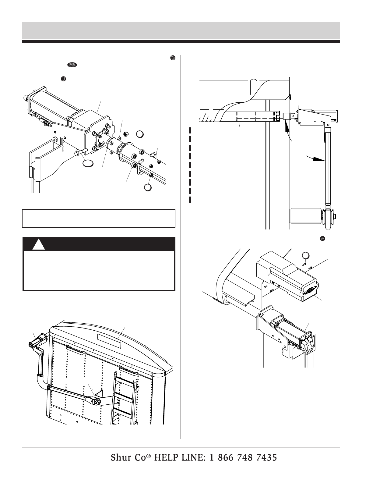
P/N 1122107 Rev. P 3" Front Roll Tube Extension Installation - Reverse Roll
Item Part # Description
1. 1122264 Drive Shaft
2. 1118194 Cartridge Clamp
3. 1128243 Motor Mount Bearing Retainer
4. 1704736 Radial Ball Bearing - 1/4" x 3/4"
5. 1120680 Motor Mount Bearing Spacer
6. 1120679 Motor Spacer
H. 1705198 Pan Hd. Self-Drilling Screw - 1/4" x 1"
N. 1700400 Self-Tapping Screw - 3/8" x 1"
Q. 1704264 Cap Screw - 3/8" x 2" - GR8
R. 1704237 Carriage Bolt - 5/16" x 1"
U. 1701543 Nylon Lock Nut - 1/4"
Z. 1704297 Nylon Lock Nut - 5/16"
BB. 1701580 Nylon Lock Nut - 3/8"
STEP 3:
Slide motor spacer over motor shaft. Slide drive shaft
over motor shaft. Fasten with screws
Q
and nuts
BB
.
Finger tighten only.
motor spacer
motor shaft
drive shaft
roll tube
STEP 1: Loosely fasten cartridge clamp to drive shaft with
screw R and lock nut Z. Insert drive shaft into roll
tube as shown. To secure drive shaft to roll tube,
tighten nut Z to 20 ft.-lbs.
motor mount
assembly
STEP 2: Install three screws H through roll tube and ats on
drive shaft collar. Drill 5/16" hole between ats and
collar, then fasten screw N through roll tube and drive
shaft collar.
drill 5/16" hole
drive
shaft
collar
1/2"
align all
screws 1/2"
from edge of
roll tube
4
3
2
1
5
6
drive shaft
cartridge
clamp
16
CAUTION
If clearance lights are in path of roll tube, install
de
flector to prevent
roll tube from damaging lights.
!
WARNING
!
Flex arms are under tension while torsion springs
are engaged. Use caution while assembling and
disassembling arms. Failure to read and follow
instructions could result in serious injury or death.
U
Z
H
H
N
N
R
Z
R
Q
Q
BB
BB
P/N 1122107 Rev. P
17
3" Front Roll Tube Extension Installation - Reverse Roll - cont'd
CAUTION
On certain trailers, clearance lights might be in
way of roll tube and can be damaged if caution is
not taken. In some instances, a ‘de
flector’ might
have to be installed to prevent
roll tube from causing
damage to lights.
!
face panel
torsion springs
motor
STEP 6: Align ex arm vertically with front of trailer and at 90°
angle to roll tube.
align flex arm
w/vertical
plane parallel
to face panel
roll tube
vertical plane
90°
STEP 5: Position motor as shown below. Make sure torsion
springs load when tarp opens.
STEP 4:
Fasten drive shaft to electric motor shaft with screw
Q
and nut
BB
. Install bearing spacers, radial ball bearings
and bearing mount retainer and secure with 1/4" lock
nuts
U
.
drive shaft
electric motor
bearing
mount
retainer
radial ball bearing
bearing spacer
NOTE: Make sure all fasteners holding motor to upper ex
arm bracket are tightened securely.
STEP 7: Fasten motor cover onto motor with screws A.
motor
cover
motor
A
U
Q
BB
Other manuals for 4500 HD Series
2
Table of contents
Other Shurco Automobile Accessories manuals


Popular Automobile Accessories manuals by other brands


ULTIMATE SPEED
ULTIMATE SPEED 279746 Assembly and Safety Advice

SSV Works
SSV Works DF-F65 manual

ULTIMATE SPEED
ULTIMATE SPEED CARBON Assembly and Safety Advice

Witter
Witter F174 Fitting instructions

WeatherTech
WeatherTech No-Drill installation instructions

TAUBENREUTHER
TAUBENREUTHER 1-336050 Installation instruction