Shurco 4500 HD Series User manual

Aluminum System
for Live-Bottom Trailers
P/N 1121682 Rev. K

Shur-Co®, LLC Terms & Conditions
SHIPPING. Orders are shipped F.O.B. from the Shur-Co®, LLC sites listed
below. No full freight isallowed or prepaid shipment accepted unless quoted
and approved in writing prior to acceptance of the order. All shipments are
made by the most reasonable means in accordance with size and weight of
order, unless specifi ed routing instructions are furnished by the customer.
Shipments are made daily via U.P.S. and common carrier. Claims for short-
ages must be made within 10 days. All claims for damages or loss in transit
must be made with the carrier. No collect calls will be accepted. To ensure
delivery of orders, we need your full street address and phone number. When
you receive your shipment, examine it carefully. Be sure all cartons listed on
the delivery sheet are accounted for. Large items may be packaged separate-
ly. If a carton is damaged, open it and inspect the contents before signing for
delivery. If merchandise is damaged, describe damage on the delivery receipt.
Failure on your part to document damaged or missing merchandise on the
delivery receipt releases the carrier of all liability; repair or replacement will be
the customer’s responsibility.
WARRANTY. We warrant all new products are free of defects in materials and
workmanship.* This warranty is effective if products are properly installed and
used for the purpose for which they were intended and applies to the original
buyer only. Except as set forth above or in any product-specifi c warranty docu-
mentation, we make no other warranties, express or implied, including but not
limited to warranties of merchantability of fi tness for a particular use.
Returns of a product for warranty must be accompanied by a Return Merchan-
dise Authorization number (RMA#), obtained by by calling Customer Service
at 866-748-7435, and sent, with freight paid by us, to Shur-Co®, LLC, 2309
Shur-Lok St., PO Box 713, Yankton, SD 57078. All products returned without
an RMA# will be refused. When we issue the RMA#, we will also issue a call
tag to have UPS (or other freight company) pick up the product. C.O.D. returns
not accepted. We will pay no storage fees for a warranty product return prior to
pick by us or the freight company. If a warranty product return is scheduled to
be picked up by us, we will pick up the product at our earliest convenience.
If a product returned is found, in our judgement, to be defective in material
or workmanship, our obligation under this warranty is limited to the repair or
replacement of the product, which will be made by us. Repair or replacement
will be at our discretion, with replacements being made using current products
performing in the equivalent function. Labor charges, other than those incurred
at our factory, including, but not limited to, any labor to install a repaired or
replacement product, are not covered under this warranty. All expenses asso-
ciated with delivering defective products to our factory and delivering repaired
or replacement products from our factory to the owner will be paid by us.
If the product returned is found, in our judgement, to be non-warrantable, the
owner will be contacted to authorize repair work, purchase of a replacement
product or return of the product, all of which will be at the owner’s expense.
Payment authorization must be received by us before any non-warrantable
product is repaired, replaced or returned. All expenses associated with deliver-
ing the repaired non-warrantable product, a replacement product or the non-
warrantable product from our factory to the owner will be paid by the owner.
In no event will we be liable for any damages of any kind to person, product or
property, including but not limited to indirect, incidental, special, consequential
or punitive damages, or damages for loss of profi ts or revenue, even if we
have been advised of the possibility of such damages. There are no warran-
ties for used products or products that have been repaired, altered, modifi ed
or subjected to misuse, negligence or accident. We will not repair or replace
products that fail or malfunction due to ordinary wear and tear, except as
expressly noted in a product-specifi c warranty. Use of non-Shur-Co®, LLC
parts in conjuction with Shur-Co®
, LLC products will void this product warranty.
*Certain products have specifi c warranties that differ from this warranty, for example motors and elec-
tronics. Product-specifi c warranty documentation is available for these items. In the event of a confl ict
between this warranty and a product-specifi c warranty, the product-specifi c warranty will govern.
RETURN POLICY. All sales fi nal. See WARRANTY above for return details.
OTHER. All prices, product listings, sizes, weights and manufacturing details
are subject to change without notice. No person is authorized to modify the
foregoing conditions of sale whatsoever.
SHUR-CO® of NORTH DAKOTA
1746 4th Ave. NW
West Fargo, ND 58078
Ph 877.868.4488 | Fax 701.277.1283
SHUR-CO® of OHIO
1100 N. Freedom, St. Rt. 88 & 14
Ravenna, OH 44266
Ph 866.356.0242 | Fax 330.297.5599
SHUR-CO® of TEXAS
34505 I-10 West, S. Frontage Rd.
Brookshire, TX 77423
Ph 866.689.0039 | Fax 281.934.3311
SHUR-CO® UK, Ltd.
Unit 41 Rochester Airport Estates
Laker Rd., Rochester, Kent ME1 3QX
Ph +44 (0)1795.473499
Fax +44 (0)871.272.8278
For more info, log on to our website:
www.shurco.com
Corporate HQ and Outlet Store
SHUR-CO® of SOUTH DAKOTA
2309 Shur-Lok St., PO Box 713
Yankton, SD 57078-0713
Ph 800.474.8756 | Fax 605.665.0501
ShurTite™ Service Centers
SHUR-CO® of CANADA
490 Elgin St., Unit #1
Brantford, Ontario N3S 7P8
Ph 800.265.0823 | Fax 519.751.3997
SHUR-CO® of SIOUX FALLS
47184 258th St., Suite B
Sioux Falls, SD 57107
Ph 844.573.9322 | Fax 605.543.5469
SHUR-CO® of ILLINOIS
Ph 866.356.0246 | Fax 217.877.8270
SHUR-CO® of OHIO
Ph 866.356.0242 | Fax 330.297.5599
SHUR-CO® of COLORADO
10220 Brighton Rd., Unit #1
Henderson, CO 80640
Ph 866.355.9173 | Fax 303.289.2298
SHUR-CO® of FLORIDA
3353 SE Gran Park Way
Stuart, FL 34997
Ph 800.327.8287 | Fax 772.287.0431
SHUR-CO® of ILLINOIS
3993 E. Mueller Ave.
Decatur, IL 62526
Ph 866.356.0246 | Fax 217.877.8270
SHUR-CO® of IOWA
3839 Midway Blvd.
Ft. Dodge, IA 50501
Ph 866.356.0245 | Fax 515.576.5578
SHUR-CO® of MICHIGAN
5100 Lakeshore Dr.
Lexington, MI 48450
Ph 800.327.8287 | Fax 772.287.0431
SHUR-CO®, LLC SERVICE AND DISTRIBUTION CENTERS
P/N 1121682 Rev. K
4500 Series HD for Live-Bottom Trailer
P/N 1121682 Rev. K
Hardware Identication.......................................................................1
Front Pivot Bracket/Pivot Pin Installation............................................2
Front Flex Arm & Electric Motor Installation ....................................3-4
Rear Mounting Beam & Pivot Bracket Installation .............................5
Rear Flex Arm Installation - Top Hinge............................................6-7
Rear Flex Arm Installation - Side Hinge...........................................8-9
Roll Tube Extension Installation - Top Hinge...............................10-12
Roll Tube Extension Installation - Side Hinge..............................13-15
Electric Mounting & Wiring ..........................................................16-20
Conversion from Electric to Manual Power ......................................21
Electric Motor Replacement .............................................................22
Replacement Parts......................................................................23-27
1. Welder
2. Hammer
3. Center Punch or Transfer Punch
4. #3 Phillips Insert Bit
5. Air or Electric Impact Wrench (9/16" deep socket)
6. 7/16" Deep Socket
7. 3/8" Combination Wrench
8. 9/16" Combination Wrench
9. 1/2" Combination Wrench
10. 1/8" Hex Wrench Long T-Handle
11. 3/16" Hex Wrench Long T-Handle (recommended)
12. 5/16" Drill Bit (for 3/8” self-tapping screws)
13. 11/32" Drill Bit
14. 13/32" Drill Bit
15. 3/8" Drill
16. 1 1/8" Hole Saw
17. 1 1/2" Hole Saw
18. 2" Hole Saw
19. Standard/Flathead Screwdriver
20. #2 Phillips Screwdriver
21. Utility Knife
22. Ratchet
23. Hack Saw (metal cutter)
24. Pliers
25. Snap Ring Pliers
26. Wire Cutters
27. Grinder
28. Tape Measure
Thank you for buying this tarping system from Shur-Co®. We appreci-
ate your condence in our products. Please read and thoroughly un-
derstand this manual before installing and/or operating this system.
Pay particular attention to important safety and operating instructions,
as well as warnings and cautions. The hazard symbol is used to
alert users to potentially hazardous conditions and is followed by cau-
tion, warning or danger messages.
Failure to READ AND FOLLOW INSTRUCTIONS could result in fail-
ure of your tarping system and/or personal injury. Your trailer require-
ments may, however, call for minor variations to these instructions.
Please inspect your tarping system periodically. Repair or replace
worn or damaged parts to your system.
QUESTIONS? CALL OUR HELP LINE:
1-866-748-7435
MON-FRI 8 AM-5 PM CENTRAL TIME
We at Shur-Co® are concerned with your safety and the safety of all
those operating this system. Therefore, we have provided safety de-
cals at various locations on your tarping system. Keep decals as clean
as possible at all times. Replace any decal that has become worn
or damaged, painted over or otherwise difcult to read. Replacement
decals are available through Shur-Co® dealers.
To prevent rust, paint all exposed metal, such as weld seams and/or
metal exposed by grinding or cutting, with corrosion-resistant paint.
!
TOOLS REQUIRED
RUST PREVENTION
SAFETY
MESSAGE TO OWNERS
TABLE OF CONTENTS
1. Always wear safety glasses during instal-
lation and operation.
2. Stay clear of moving parts.
3. No other use of this system is authorized,
except as designed.
SAFETY INSTRUCTIONS

P/N 1121682 Rev. K
Hardware Identication
1
Inspect 4500 Series HD kit upon arrival.
1704946 Flanged Top Lock Nut - 5/16"
1700429 Flat Washer - 3/8"
1703487 Cap Screw - 5/16" x 1 1/2"
1700419 Nylon Lock Nut - 5/16"
1701045 Cap Screw - 5/16" x 3/4"
1700407 Hex Nut - 3/8"
1700434 Lock Washer - 3/8"
1702891 Cap Screw - 3/8" x 1 1/4"
1118318
Spacer Washer -
1/4" x 1.81" x 1.28"
1201022 Cap Screw - 5/16" x 3 1/2"
1702890 Flat Washer - 1 1/4"
1701543 Nylon Lock Nut - 1/4"
1700400 Self-Tapping Screw - 3/8" x 1"
1700428 Flat Washer - 5/16"
1700381 Cap Screw - 1/4" x 1" O
P
A
B
D
E
F
H
Q
S
T
U
V
b
c
1700408 Hex Nut - 1/4"
1700418 Centerlock Nut - 3/8"
1702573 Cap Screw - 3/8" x 2 1/2"
1700436 Lock Washer - 1/4"
C
1702926 Cap Screw - 5/16" x 7/8"
a
NOTE: Use lock washers and nuts with
self-tapping screws whenever possible.
A minimum material thickness of 3/16" is
required in order to use self-tapping screws
without lock washers and nuts. Drill 13/32"
holes if lock washers and nuts are used.
Drill 5/16" holes if lock washers and nuts
are not used.
1120291 Pivot Bracket Washer
1704264 Cap Screw - 3/8" x 2" - Grade 8
G
1701580 Nylon Lock Nut - 3/8"
1700403 Self-Tapping Screw - 1/4" x 3/4"
1704338 Self-Tapping Screw - 1/4" x 1"
J
K
1700427 Flat Washer - 1/4"
R
h
d
N
1704367 Cap Screw - #10 x 3/4"
1700398 Self-Drilling Screw - 1/4" x 3/4"
M
L
W
X
1704971 Carriage Bolt - 5/16" x 2 1/4"
1704943 Shoulder Bolt - 3/8" x 2" - 5/16" x 1/2" Thd.
1705198 Self-Drilling Screw - 1/4" x 1"
Z
1704931 Flanged Nylon Lock Nut - 5/16"
e
f
g
Y
1701455 Carriage Bolt - 5/16" x 2 1/2"

P/N 1121682 Rev. K
2
Front Pivot Bracket Installation
rivets off
center
STEP 1: Locate front pivot mount bracket on passenger side
of trailer so center of pivot lies within shaded area
shown below. Measure 41" down from top of cap or
43" from top of windshield.
4"
4"
4"
4"
6"
4"
4"
6"
rivets on
center line
43"
c
l
locate center
of pivot inside
shaded area
STEP 2: Place pivot mount brackets on trailer in orientation
shown below. Using brackets as guide, mark mounting
hole locations.
e
d
J
e
X
d
J
RIVETS/CORRUGATION OFF CENTER
RIVETS/CORRUGATIONS ON CENTER center of
trailer
NOTE: Read entire section before drilling holes. Determine if
rivets on front of trailer are centered or off center.
NOTE: Mount front pivot bracket into support braces on trailer,
if possible. If bracket cannot be mounted into support braces,
reinforce mounting area with backer plate for adequate support.
Before drilling any holes, make sure ex arm will have a clear
pathway to operate.
Item Part # Description
1. 1116920 Pivot Pin - 4 Spring
2. 1116919 Vertical Pivot Mount Bracket - 7 1/4" Standoff
1117927 Vertical Pivot Mount Bracket - 12 1/4" Standoff
1117767 Pivot Mount Bracket - 1 1/4"
3. 1120361 Pivot Backer Plate - 5" x 16"
1120418 Pivot Backer Plate - 5" x 20"
J. 1702891 Cap Screw - 3/8" x 1 1/4"
x. 1700407 Hex Nut - 3/8"
d. 1700434 Lock Washer - 3/8"
e. 1700429 Flat Washer - 3/8"
pivot bracket
pivot pin
STEP 1: Fasten pivot pin to pivot bracket with keyway facing
downward as shown.
keyway in pivot pin
must face downward
PIVOT PIN INSTALLATION
e
31
d
e
e
d
STEP 3:
Remove rivets and mount brackets into rivet holes. If this
is not possible, drill 13/32" holes in trailer. Fasten with 3/8"
x 1 1/4" cap screws, at washers, lock washers and nuts.
2
c
l
c
l
c
l
2
41"
J
J
X
X
X
e
h
h
NOTE: Use pivot bracket washers only when horizontal
corrugation on trailer skin prevents bracket from contacting skin.
STEP 4: If installing pivot bracket or pivot mount bracket on
horizontally corrugated trailer skin, center bracket
between corrugations and use brackets as guide to
mark hole locations. Mark and drill 13/32" holes in
trailer and fasten with 3/8" x 1 1/4" cap screws, at
washers, lock washers, pivot bracket washers and
nuts. Locate pivot bracket washers between pivot
bracket and trailer skin as shown.
W
dc
J
pivot bracket
corrugated trailer skin locate pivot bracket
washers between pivot
bracket & trailer skin
HORIZONTALLY CORRUGATED TRAILERS
g
FRONT OF TRAILER

P/N 1121682 Rev. K
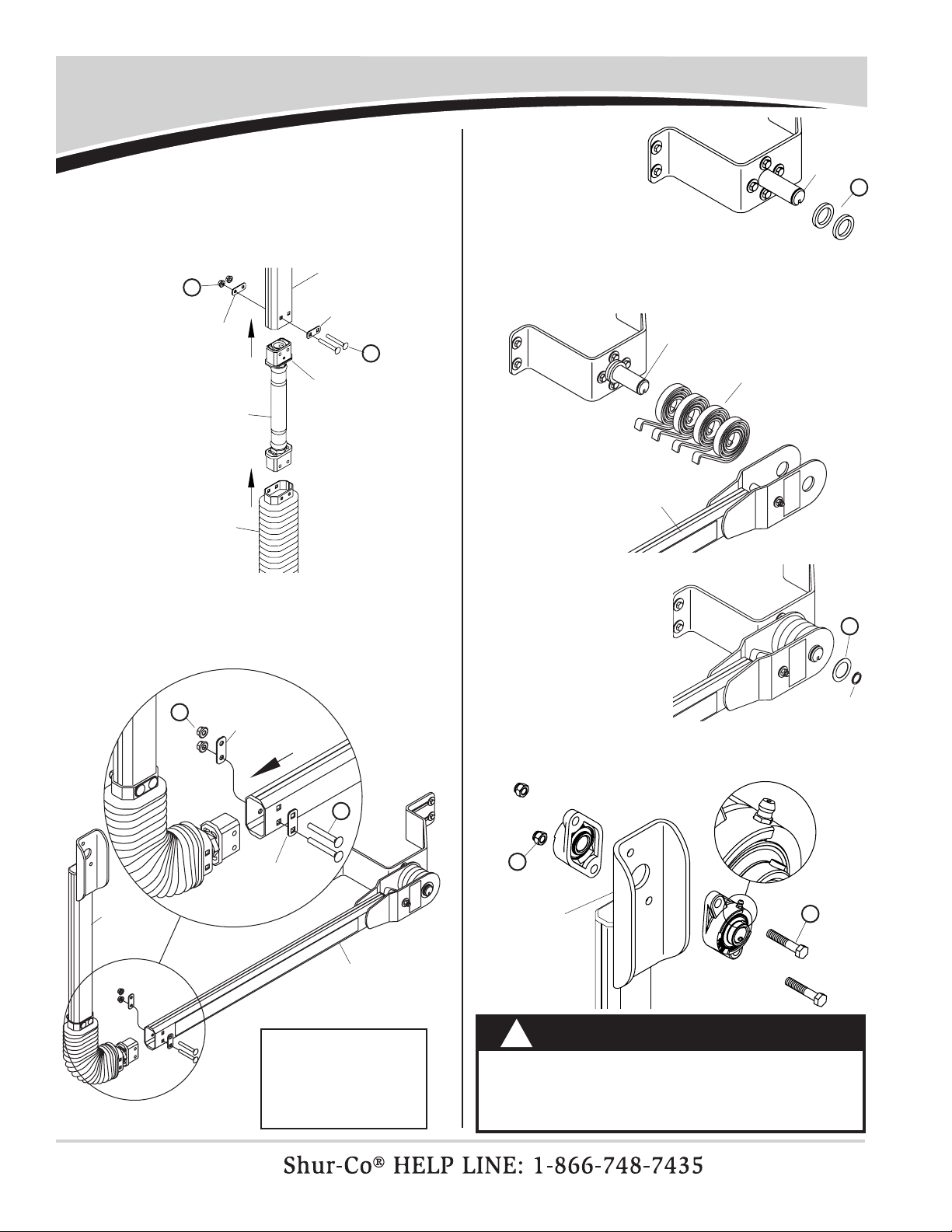
Front Flex Arm & Electric Motor Installation
3
1
pivot mount
bracket assembly
3
2
STEP 1: Assemble spacer washers onto pivot pin.
pivot pin
S
6
5
4
7P
Item Part # Description
1. Flex Arm Assembly - Std.
Flex Arm Assembly - 7 1/4"
2. 1111027 Spiral Torsion Spring
3. 1702888 External Retaining Ring - 1-1/4"
4. SMARTwire™ Encoder Wire w/Plate -
18 Ga. - 10' 9"
5. 1704987 SMARTwire™ - 6 Ga. Plug x
1/4” Terminal x 10’9”
6. 1704751 Harness Lock Pin - 1/4" x 7/8"
7. 1702108 Wire Clip - 3/4" ID
8. 1121414 Bellow Plate - Square Holes
9. 1121413 Bellow Plate - Round Holes
P. 1700398 Self-Drilling Screw - 1/4" x 3/4"
F. 1701455 Carriage Bolt - 5/16" x 2 1/2"
O. 1700403 Self-Tapping Screw - 1/4" x 3/4"
S. 1700408 Hex Nut - 1/4"
V. 1704931 Flanged Nylon Lock Nut - 5/16"
a. 1700436 Lock Washer - 1/4"
b. 1700427 Flat Washer - 1/4"
f. 1702890 Flat Washer - 1-1/4"
g. 1118318 Spacer Washer - 1/4” x 1.28”
b
ag
f
O
g
8
V
F
9
flex arm joint w/bellow
lower flex arm
assembly
NOTE: Motor assembly on upper ex arm must face toward
trailer as shown.
upper flex
arm w/motor
V
F
bellow plate
w/square holes
STEP 2: Align holes in bellow and bellow plates with holes in
lower ex arm assembly as shown. Fasten with 5/16"
x 2 1/2" carriage bolts and lock nuts.
bellow plate
w/round holes
NOTE: Do not remove cable tie
from front ex arm and motor
assembly until installation is
complete. See step 9.
WARNING
Do not stand or climb on flex arm. Standing or climb-
ing on flex arm could result in fall/impact causing
serious injury or death.
!
P/N 1121682 Rev. K
4
Front Flex Arm & Motor Installation - continued
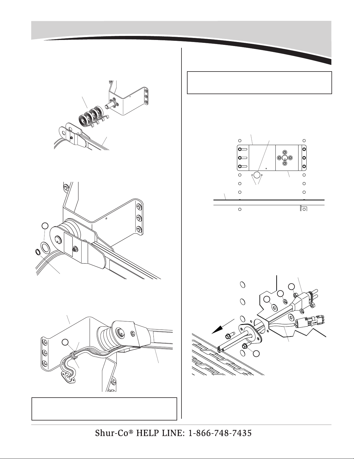
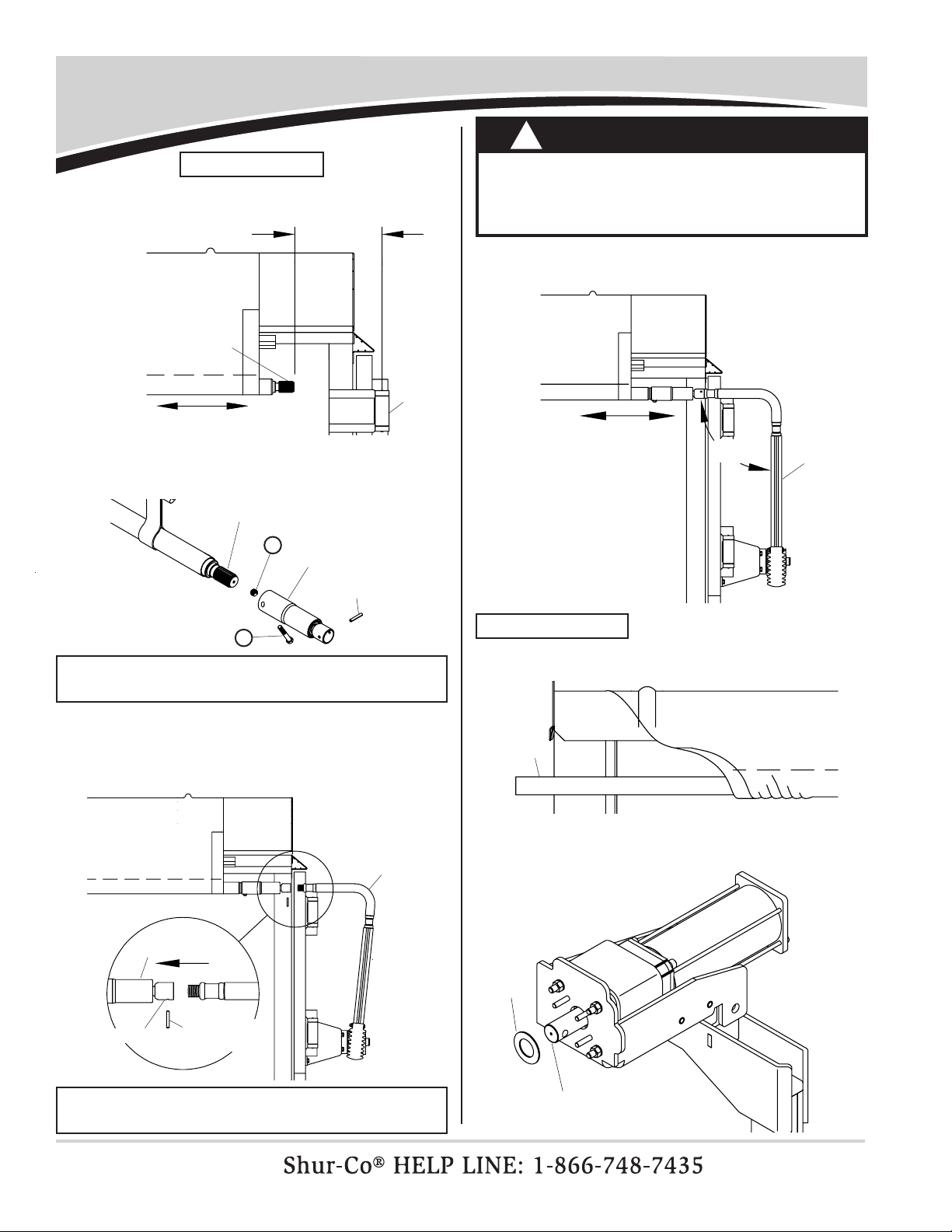
STEP 7: Align adapter plug with 1 1/2" hole. Using wiring plate
as guide, mark and drill two 7/32" holes as shown.
STEP 6: Measure 11" horizontally from center line of trailer and
1" down from lower edge of pivot bracket. Mark and
drill 1 1/2" hole through trailer skin.
drill 1 1/2" hole
pivot bracket
catwalk drill two
7/32" holes
pivot bracket
STEP 8: Fasten adapter plug to front of trailer with 1/4" x 3/4"
self-tapping screws, at washers, lock washers and
nuts.
smartwire™ plug
NOTE: Wire lengths are predetermined. Before installing
SMARTwire™ components, review and conrm wire routing
so wires reach components with ample room for
connection.
STEP 5: Choose appropriate pilot hole on pivot bracket to route
6-ga. wire from ex arm through trailer skin. Fasten
wire clip to pilot hole with 1/4" x 3/4" self-drilling screw.
NOTE: Fasten wire clip to pilot hole on opposite side of pivot
bracket from ex arm to prevent wire from being pinched
during operation.
P
wire clip
pilot
hole
flex arm
pivot bracket
O
b
a
S
STEP 4: Secure with 1 1/4" at washer and retaining ring.
retaining ring
f
STEP 3: Assemble spiral torsion springs and lower ex arm
onto pivot pin. Hook springs over 3/8" x 3 1/2" cap
screw and spacer tube.
spiral torsion springs
lower flex arm
to motor/arm
encoder wire
STEP 9: Remove cable tie from front arm/motor assembly
before operating system.
P/N 1121682 Rev. K
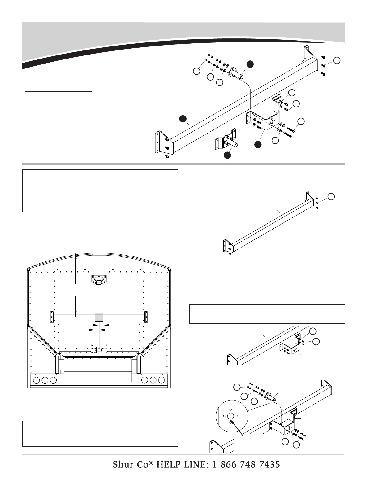
Rear Mounting Beam & Pivot Bracket Installation
5
Item Part # Description
1. 1116920 Pivot Pin - 4 Spring
2. 1116919 Vertical Pivot Mount Bracket
1117767 Low-Prole Pivot Mount Bracket
3. ___*___ Mounting Beam
4. 1117816 Pivot Bracket - Side Hinge
H. 1700400 Self-Tapping Screw - 3/8" x 1"
J. 1702891 Cap Screw - 3/8" x 1 1/4"
X. 1700407 Hex Nut - 3/8"
d. 1700434 Lock Washer - 3/8"
e. 1700429 Flat Washer - 3/8"
* Specify size
1
X
3
2
d
e
H
H
J
e
STEP 4: Center pivot bracket vertically on mounting beam.
Move pivot bracket from left to right until pivot pin falls
in shaded area shown in step 1. Using holes in pivot
bracket as guide, mark and drill 5/16" holes. Fasten
pivot bracket to beam with 3/8" x 1" self-tapping
screws and washers.
STEP 3: Remove rivets and fasten mounting beam into rivet
holes. If not possible, drill 5/16" holes in trailer. Fasten
with 3/8" x 1" self-tapping screws.
STEP 1: Locate mounting beam so center of mounting beam
lies within shaded area shown.
NOTE: Fasten rear mounting beam to structural door only.
DO NOT mount beam to door skin. Tarping system will fail if
beam is mounted to door skin.
Before drilling any holes, make sure ex arm has clear
pathway to operate. Read entire section before drilling.
STEP 5: Fasten pivot pin to pivot bracket with keyway facing
downward as shown.
NOTE: If using optional low-prole pivot mount bracket,
complete step 5 before step 4.
42"±3"
3"
3"
c
l
NOTE: On trailers with knife gate, mounting beam must be
centered from left to right. Verify bolt locations do not interfere
with operation of knife gate or knife gate track.
STEP 2: Place mounting beam on trailer as shown. Using beam
as guide, determine mounting hole locations.
H
mounting beam
mounting beam
H
pivot bracket
pivot bracket
pivot pin
X
de
eJ
slot in pivot
pin must face
downward
4
e
e
P/N 1121682 Rev. K
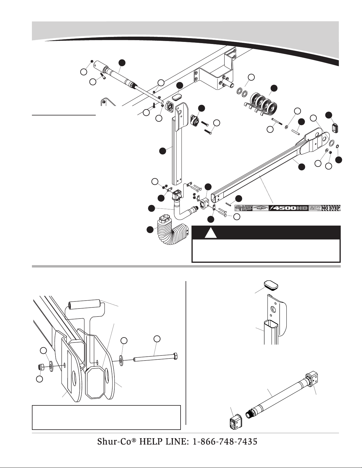
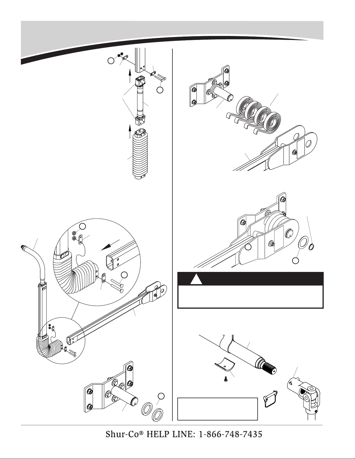
STEP 1: Install cap plug on lower ex arm. Fasten spacer tube
into spring support bracket on lower ex arm with
5/16" x 3 1/2" cap screw, two at washers and nylon
lock nut.
Rear Flex Arm Installation - Top Hinge
6
M
c
c
W
spacer tube
spring support
bracket on
lower flex arm
NOTE: Insert cap screw through ex arm so head of screw is
on inside of assembly (toward trailer). Warning label must be
in plain view on outside of assembly.
1
3
2
4
5
6
7
cap plug
warning decal
Y
L
g
W
D
W
c
M
c
d
F
V
9
8
13
7
12
10
11
K
Item Part # Description
1. 1116990 Gate Flex™
2. 1111027 Spiral Torsion Spring
3. 1121649 Upper Flex Arm - Gate Flex™
4. 1702888 Retaining Ring - 1 1/4”
5. 1121999 Lower Flex Arm w/Warning Decals
6. 1117033 Spacer Tube - .35" x 2 5/8"
7. 1704892 Cap Plug
8. 1121414 Bellow Plate - Square Holes
9. 1121413 Bellow Plate - Round Holes
10. 1704891 End Fitting
11. 1121655 Flex Arm Joint Assembly
12. 1704703 Flange Bearing - 20 mm - 2 Bolt
13. 1704775 Bellow
14. 1701360 Spring Pin - 1/4" x 1 3/4"
D. 1703487 Cap Screw - 5/16" x 1 1/2"
F. 1701455 Carriage Bolt - 5/16" x 2 1/2"
K. 1704264 Cap Screw - 3/8" x 2" - Grade 8
L. 1702573 Cap Screw - 3/8" x 2 1/2"
M. 1201022 Cap Screw - 5/16" x 3 1/2"
V. 1704931 Flanged Nylon Lock Nut - 5/16"
W. 1700419 Nylon Lock Nut - 5/16"
Y. 1700418 Centerlock Nut - 3/8"
Z. 1701580 Nylon Lock Nut - 3/8"
a. 1700428 Flat Washer - 5/16"
f. 1702890 Flat Washer - 1 1/4"
g. 1118318 Spacer Washer - 1/4" x 1.81"
Z
STEP 2: Install cap plug on rear upper ex arm.
cap plug
upper flex arm
STEP 3: Thread end tting onto end of ex arm joint assembly.
Tighten so end tting is parallel to existing end tting.
flex arm
joint
existing
end fitting
w/spring pin
end fitting
14
WARNING
Do not stand or climb on flex arm. Standing or climb-
ing on flex arm could result in fall/impact causing
serious injury or death.
!
P/N 1121682 Rev. K
Rear Flex Arm Installation - Top Hinge - continued
7
STEP 5: Align holes in end ttings and bellow plates with holes
in lower ex arm assembly as shown. Temporarily
install 5/16" x 2 1/2" carriage bolts and lock nuts.
lower flex
arm assembly
upper
flex arm
assembly
STEP 8: Secure with 1 1/4"
at washer and
retaining ring. f
retaining
ring
F
V
bellow plate
w/square holes
upper flex arm
flex arm joint
assembly
bellow
STEP 4: Insert ex arm joint into upper ex arm and slide
bellow over ex arm joint. Align holes in upper ex
arm, bellow plates, ex arm joint and bellow. Fasten
with 5/16" carriage bolts and anged nylon lock nuts.
S
F
bellow plate
w/square hole
bellow plate
w/round hole
STEP 9: Position ange bearings as shown and fasten to bearing
mount plate with 3/8" x 2" cap screws and lock nuts.
bearing
mount
plate
K
Z
WARNING
Flex arms are under tension while torsion springs are
engaged. Use caution while assembling and disas-
sembling arms. Failure to read and follow instructions
could result in serious injury or death.
!
bellow plate
w/round holes
STEP 6: Assemble
spacer washers
onto pivot pin.
g
pivot pin
STEP 7: Assemble spiral torsion springs and lower ex arm
onto pivot pin. Hook springs over 5/16" x 3 1/2" cap
screw and spacer tube.
pivot pin
lower flex arm
spiral torsion
springs
pinned end fitting
NOTE: Do not tighten
nuts as adjustments
will be made later. See
“Roll Tube Extension
Installation - Top Hinge”

P/N 1121682 Rev. K Rear Flex Arm Installation - Side Hinge
8
Item Part # Description
1. 1117777 Roll Tube Bearing Pack
2. 1121680 Upper Flex Arm Joint Assembly
3. 1121738 Upper Flex Arm - Side Hinge
4. 1700445 Spring Pin - 1/4" x 1 1/2"
5. 1704775 Bellow
6. 1121999 Lower Flex Arm w/Warning Decals
7. 1702888 Retaining Ring - 1 1/4"
8. 1117033 Spacer Tube - .35" x 2 5/8"
9. 1111027 Spiral Torsion Spring
10. 1704892 Cap Plug
11. 1121679 Lower Flex Arm Joint Assembly
12. 1121413 Bellow Plate - Round
13. 1121414 Bellow Plate - Square
E. 1704971 Carriage Bolt - 5/16" x 2 1/4"
F. 1701455 Carriage Bolt - 5/16" x 2 1/2"
L. 1702573 Cap Screw - 3/8" x 2 1/2"
M. 1201022 Cap Screw - 5/16" x 3 1/2"
V. 1704931 Flanged Nylon Lock Nut - 5/16"
W. 1700419 Nylon Lock Nut - 5/16"
Y. 1700418 Centerlock Nut - 3/8"
c. 1700428 Flat Washer - 5/16"
f. 1702890 Flat Washer - 1 1/4"
g. 1118318 Spacer Washer - 1/4" x 1.81"
M
c
c
W
spacer tube
STEP 1: Install cap plug on lower ex arm. Fasten spacer tube
into spring support bracket on lower ex arm with
5/16" x 3 1/2" cap screw, two at washers and nylon
lock nut.
spring support
bracket on lower
flex arm
NOTE: Insert cap screw through ex arm so head of screw is
on inside of assembly (toward trailer). Warning label must be
in plain view on outside of assembly.
STEP 2: Insert upper ex arm joint into upper ex arm and
align bellow plates with square holes as shown.
Fasten with 5/16” carriage bolts and anged nylon
lock nuts.
upper flex
arm joint
upper flex arm
12
9
W
7
6c
5
8
3
pivot pin
warning decal
cap plug
10
f
c
M
L
Y4
F
V
E
F
V
11
12
13
13
13
E
V
bellow plates
w/square holes
g
12
WARNING
Do not stand or climb on flex arm. Standing or climb-
ing on flex arm could result in fall/impact causing
serious injury or death.
!
P/N 1121682 Rev. K
Rear Flex Arm Installation - Side Hinge - continued
9
STEP 5: Assemble spacer
washers onto
pivot pin.
STEP 6: Assemble spiral torsion springs and lower ex arm
onto pivot pin. Hook springs over 5/16" x 3 1/2" cap
screw and spacer tube.
STEP 7: Secure with 1 1/4" at washer and retaining ring.
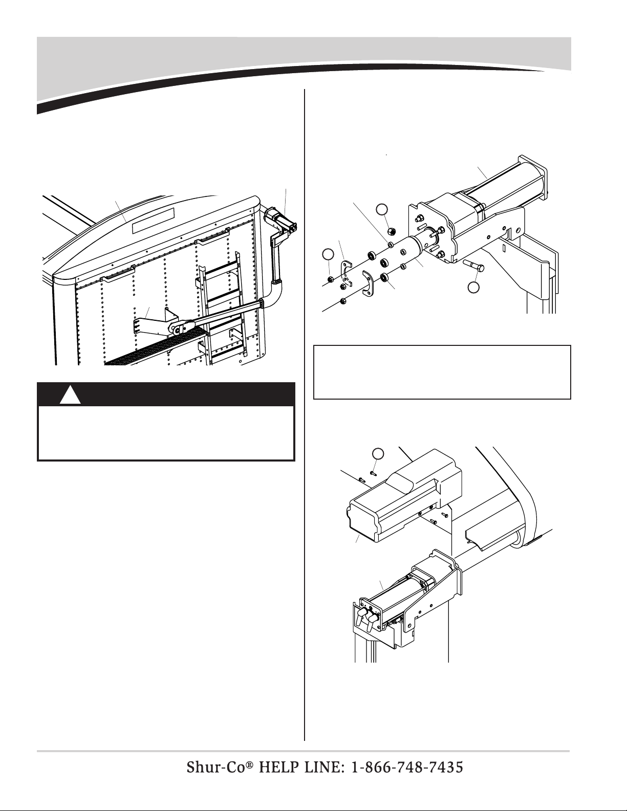
STEP 8: Roll tarp closed over box with roll tube hanging below
latchplate. Remove crank assembly and U-clamps
from roll tube.
CAUTION
Do not open or close tarp without U-joint se-
curely fastened to splined shaft with wire lock
pin. Failure to do so could result in injury.
!
crank assembly
u-clamp
roll tube
retaining
ring
pivot pin
lower flex arm
spiral torsion springs
pivot pin
NOTE: Remove any existing
returns, such as cable return,
bungee return, etc.
g
D
f
STEP 3: Insert lower flex arm joint
into upper ex arm and slide
bellow over joint. Align holes
in upper flex arm, bellow
plates, lower ex arm joint
and bellow. Fasten with 5/16"
carriage bolts and lock nuts.
STEP 4: Insert lower ex arm joint into lower ex arm assembly
with bellow on outside of arm.
Align holes in lower
ex arm, bellow plates, end tting and bellow. Fasten
with 5/16" carriage bolts and lock nuts.
F
V
bellow
plate w/
rnd. holes
lower
flex
arm
joint
plate w/
sq. holes
F
V
upper flex
arm assembly
bellow plate
w/square holes
lower flex
arm assembly
bellow plate
w/round holes
pinned end fittings
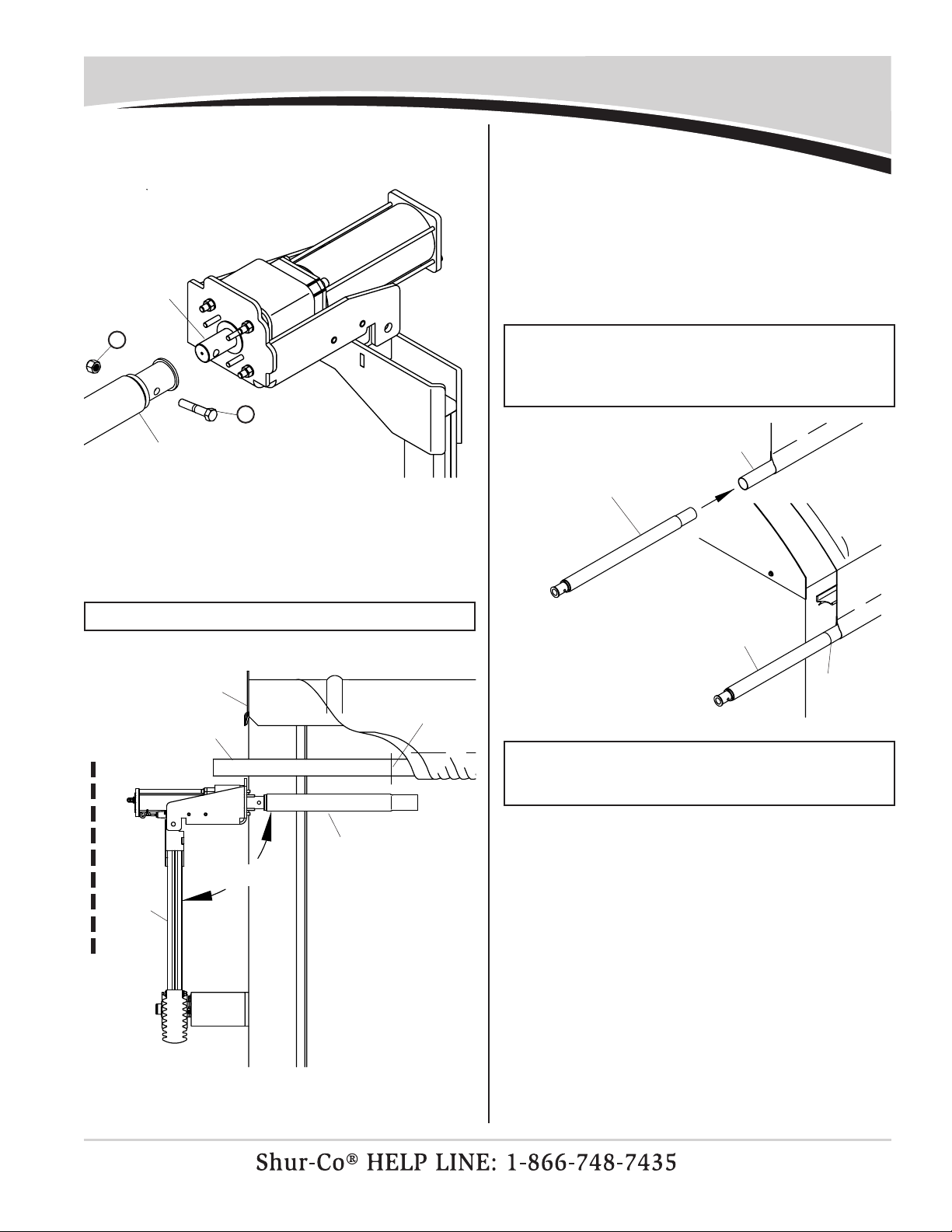
P/N 1121682 Rev. K Roll Tube Extension Installation - Top Hinge
10
gate hinge pin
splined shaft
STEP 1: Adjust roll tube forward or backward to align end of
splined shaft with gate hinge pin.
adjust roll tube
NOTE: If hinge depth is 0" to 4", set end of splined shaft 4"
in from back of gate.
STEP 2: Slide Gate Flex™ completely over splined shaft on
roll tube. Fasten with 3/8" x 2 1/2" cap screw and
centerlock nut.
NOTE: Do not remove splined shaft. Splined shaft will be
used if system is switched to manual operation.
gate flex™
splined shaft
4"
Y
L
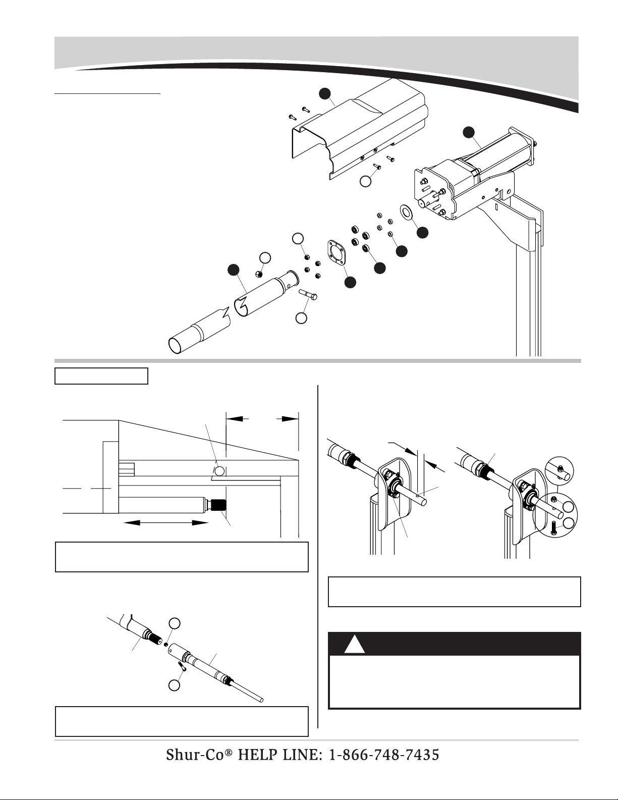
Item Part # Description
1. Flex Arm Assembly w/Motor - Std.
Flex Arm Assembly w/Motor - 7 1/4"
2. 1120680 Motor Mount Bearing Spacer
3. 1704736 Radial Ball Bearing - 1/4" x 3/4"
4. 1120681 Motor Mount Bearing Retainer
5. 1120679 Motor Spacer
6. 1120697 Roll Tube Extension w/Drive Shaft - 34.43"
1120698 Roll Tube Extension w/Drive Shaft - 45.37"
1120699 Roll Tube Extension w/Drive Shaft - 74.87"
7. 1704982 Motor Cover - Black
K. 1704264 Cap Screw - 3/8" x 2" - Grade 8
N. 1704367 Hex Flange Cap Screw - #10 x 3/4"
T. 1701543 Nylon Lock Nut - 1/4"
Z. 1701580 Nylon Lock Nut - 3/8"
4
5
3
T
K
Z2
1
6
STEP 3: Slide bearing shaft on Gate Flex™ through ange
bearing on upper ex arm. Drill 5/16" hole through
bearing shaft. Insert 5/16" x 1 1/2" cap screw through
hole and secure with lock nut.
bearing flange
bearing shaft on
gate flex™
1"
drill
5/16"
hole
NOTE: Do not leave unattended until ex arm is securely
fastened to roll tube extension as shown.
WARNING
Flex arms are under tension while torsion springs
are engaged. Use caution while assembling and
disassembling arms. Failure to read and follow
instructions could result in serious injury or death.
!
N
7
REAR OF TRAILER
D
W
P/N 1121682 Rev. K
Roll Tube Extension Installation - Top Hinge - continued
11
STEP 7: Hold ex arm with motor and roll tube extension in
vertical plane to trailer and 90° to roll tube. Mark and
cut roll tube at location shown.
vertical plane
flex
arm
roll tube
roll tube
extension
cut here
face panel
90°
NOTE: Two people required for safe installation.
STEP 8: Unfasten and remove motor from roll tube extension.
Remove roll tube extension from roll tube. Cut roll tube
at marked location.
roll tube extension
w/drive shaft roll tube
STEP 9: Insert swaged end of roll tube extension w/drive shaft
into roll tube. Align extension straight with roll tube and
weld all around. Grind smooth.
weld &
grind
smooth
roll tube
extension
w/drive shaft
NOTE: Pull roll tube away from tarp and trailer before
welding to protect from weld spatter. Align roll tube extension
straight with roll tube before welding so tarping system will
roll smoothly.
NOTE: To prevent rust,
paint all exposed metal,
such as weld seams and/
or metal exposed by
grinding or cutting, with
corrosion-resistant paint.
STEP 4: Align upper ex arm in vertical plane
90° to roll tube. Tighten set screws in ush mount
bearing.
align upper flex arm on vertical
plane 90° to roll tube
roll tube
vertical plane
upper
flex
arm
tighten
set
screws
90°
STEP 5: Slide tarp back on roll tube.
roll tube tarp
STEP 6A: Slide motor spacer over motor shaft.
STEP 6B: Slide roll tube extension over motor shaft. Fasten with
3/8" x 2" cap screws and lock nuts. Finger tighten only.
Fasten roll tube extension to motor mount bracket:
motor
spacer
motor shaft
roll tube
extension
motor shaft
FRONT OF TRAILER
K
Z

P/N 1121682 Rev. K Roll Tube Extension Installation - Top Hinge - continued
12
NOTE: Verify ex arm is on vertical plane and
parallel to
face panel before proceeding. Make sure all fasteners holding
motor to upper ex arm bracket are tightened securely.
STEP 14:
Place wrench on ex arm joint next to lower ex arm.
Turn ex arm joint counter-clockwise (up) to move
upper ex arm and Gate Flex™ from side to side.
drill 1/4" hole
spring pin
rear of
trailer
top view
flex arm & gate flex™
will move side to side
turn counter-
clockwise (up)
STEP 16:
Drill 1/4" hole through lower ex arm and ex arm joint
as shown. Install 1/4" x 1 3/4" spring pin into drilled hole.
STEP 15: Keep turning ex arm joint until
Gate Flex™
is parallel
to side of trailer and 90° to rear door.
90°
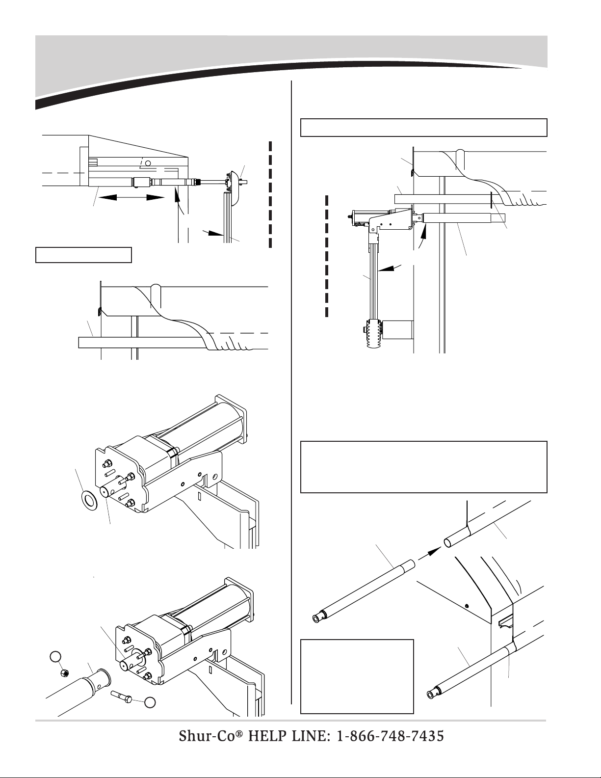
STEP 11: Refasten and
secure roll tube to electric motor shaft
with 3/8" x 2" cap screw and lock nut. Install bear-
ing spacers, radial ball bearings and bearing mount
retainer and secure with 1/4" lock nuts.
roll tube extension
electric motor
bearing
mount
retainer
radial
ball bearing
bearing
spacer
WARNING
!
Flex arms are under tension while torsion springs
are engaged. Use caution while assembling and
disassembling arms. Failure to read and follow
instructions could result in serious injury or death.
STEP 10: Slide roll tube/roll tube extension weldment back into
position and align upper ex arm on front of trailer.
Follow step 11 to install motor, positioning motor as
shown below. Make sure torsion springs load when
tarp opens.
face panel
pivot bracket
7/16"
STEP 13: Refasten tarp to roll tube with existing
U-clamps and screws. Tighten all fasteners
securely. Tighten front and rear ex arm connections.
STEP 12: Fasten motor
cover onto mo-
tor with #10 x
3/4" screws. motor
cover
motor
N
K
Z
T
STEP 17:
Remove tension from rear arm by lowering roll tube
to lowest position on side of trailer. Disconnect Gate
Flex™ from splined shaft on roll tube. Remove carriage
bolts and plates from lower arm. Slide bellow into posi-
tion and re-assemble carriage bolts and plates. Tighten
nuts and reconnect Gate Flex™ to splined shaft.
flex arm joint
lower flex arm
or less
NOTE: Do not overtighten
or plastic insert will break.
REAR OF TRAILER
P/N 1121682 Rev. K
Roll Tube Installation - Side Hinge
13
WARNING
Flex arms are under tension while torsion springs
are engaged. Use caution while assembling
and disassembling arms. Failure to read and follow
instructions could result in serious injury or death.
!
STEP 1: Adjust roll tube forward or backward so end of splined
shaft is 11" from center line of gate hinge pin.
STEP 2: Slide roll tube bearing pack completely over splined
shaft on roll tube. Fasten with 3/8" x 2 1/2" cap screw
and centerlock nut.
STEP 3:
Screw upper ex arm assembly into roll tube bear-
ing pack. Drill 1/4" hole through bearing pack and
secure ex arm joint to bearing pack with 1/4" x 1
1/2" spring pin.
STEP 4: Align upper ex arm in vertical plane 90° to roll tube.
STEP 5: Slide tarp back on roll tube.
NOTE: Do not remove splined shaft. Splined shaft will be
needed if system is switched to manual operation.
roll tube
NOTE: Do not leave unattended until ex arm is securely
fastened to roll tube extension as shown.
11"
adjust roll tube
gate
hinge
pin
splined shaft
splined shaft
roll tube
bearing pack
upper
flex
arm
adjust roll tube
90°
upper
flex arm
assembly
roll tube
bearing pack
1/4" x1 1/2"
spring pin
drill 1/4" hole
STEP 6A: Slide motor spacer over motor shaft.
Fasten roll tube extension to motor mount bracket:
motor
spacer
motor shaft
REAR OF TRAILER
FRONT OF TRAILER
Y
L
spring pin
P/N 1121682 Rev. K Roll Tube Installation - Side Hinge - continued
14
STEP 7: Hold ex arm with motor and roll tube extension in
vertical plane to trailer and 90° to roll tube. Mark and
cut roll tube at location shown.
STEP 8: Unfasten and remove motor from roll tube extension.
Remove roll tube extension from roll tube. Cut roll
tube at marked location.
STEP 9: Insert swaged end of roll tube extension w/drive shaft
into roll tube. Align extension straight with roll tube
and weld all around. Grind smooth.
NOTE: Two people are required for safe installation.
NOTE: Pull roll tube away from tarp and trailer before
welding to protect from weld spatter. Align roll tube extension
straight with roll tube before welding so tarping system will
roll smoothly.
vertical plane
flex
arm
roll tube
roll tube
extension
cut here
face panel
90°
roll tube extension
w/drive shaft
roll tube
weld &
grind
smooth
roll tube
extension
w/drive shaft
NOTE: To prevent rust, paint all exposed metal, such as
weld seams and/or metal exposed by grinding or cutting,
with corrosion-resistant paint.
STEP 6B: Slide roll tube extension over motor shaft. Fasten with
3/8" x 2" cap screws and lock nuts. Finger tighten only.
motor shaft
roll tube extension
K
Z
P/N 1121682 Rev. K
Roll Tube Installation - Side Hinge - continued
15
WARNING
Flex arms are under tension while torsion springs
are engaged. Use caution while assembling
and disassembling arms. Failure to read and follow
instructions could result in serious injury or death.
!
NOTE: Verify ex arm is on vertical plane and parallel to
face panel before proceeding. Make sure all fasteners
holding motor to bearing mount plate to upper ex arm are
tightened securely.
STEP 13: Refasten tarp to roll tube with existing U-clamps and
screws. Tighten all fasteners securely. Tighten front
and rear ex arm connections.
STEP 10: Slide roll tube/roll tube extension weldment back into
position and align upper ex arm on front of trailer.
Follow steps 6 A and B to install motor, positioning
motor as shown below. Make sure torsion springs
load when tarp opens.
STEP 11: Refasten and
secure roll tube to electric motor shaft
with 3/8" x 2" cap screw and lock nut. Install bear-
ing spacers, radial ball bearings and bearing mount
retainer and secure with 1/4" lock nuts.
roll
tube
electric motor
bearing
mount
retainer
radial
ball
bearing
bearing
spacer
face panel
pivot bracket
electric motor
STEP 12: Fasten motor cover onto motor with #10 x 3/4" screws.
motor
cover
motor
K
Z
T
N
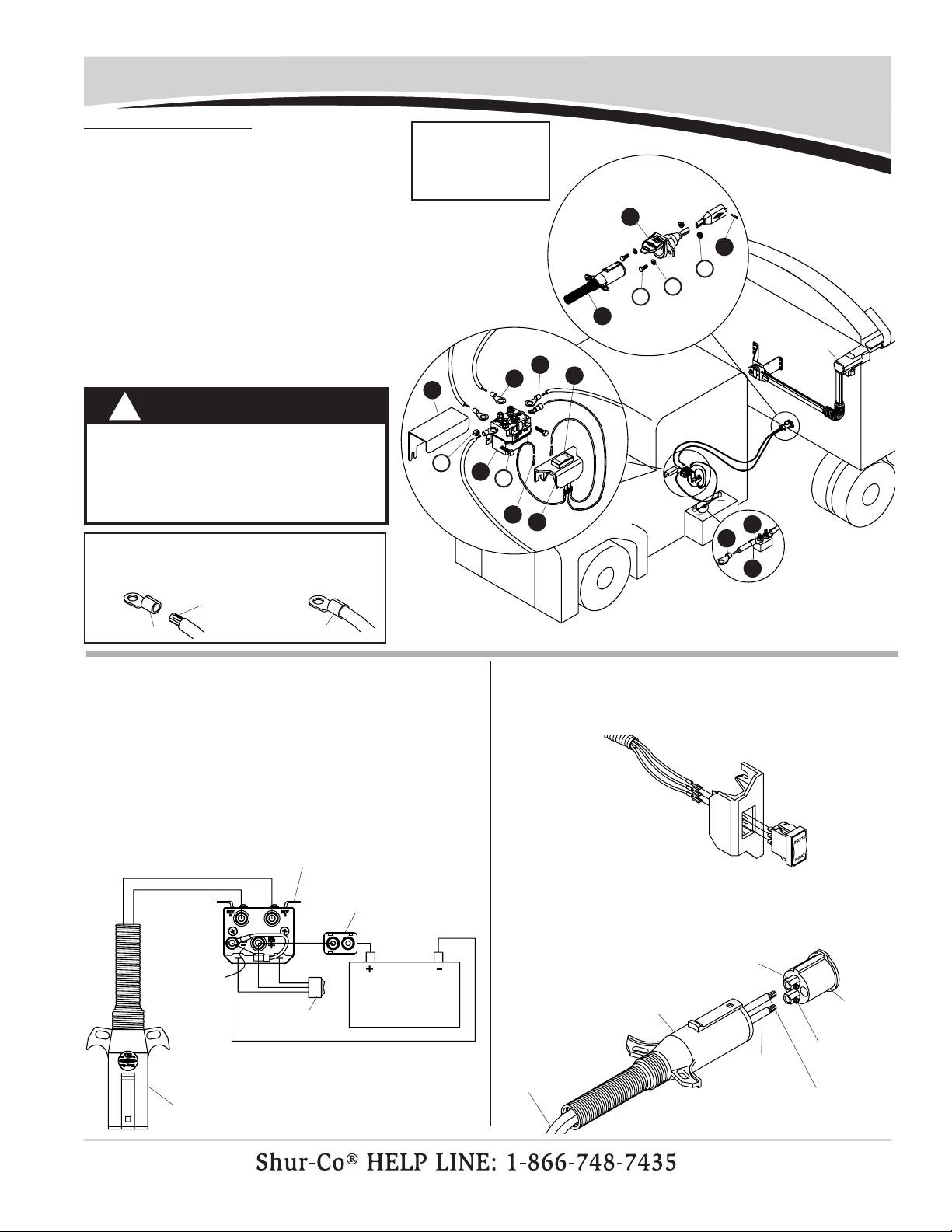
P/N 1121682 Rev. K Rocker Switch - Cab Wiring
16
STEP 2: Mount solenoid in suitable location - ventilated area
near battery is ideal. Determine best route for wire,
usually along frame with existing wire harness. Run
6-ga. wire from conductor plug to solenoid and from
power supply to solenoid as shown in diagram. Run
14-ga. wires from solenoid to switch.
STEP 3: Locate rocker switch in convenient operating loca-
tion. Switch can be mounted in cab, on dash panel,
on driver side door jamb or in a convenient location
outside cab.
connect wires to
switch as shown
set screw
insert
conductor plug
positive wire -
colored stripe
on top
brass contact
wire
STEP 4: Unfasten and remove insert from conductor plug. Feed
6-ga. wire through plug and into brass contacts on
insert. Tighten set screws to secure wires. Replace
insert into conductor plug and secure screw.
negative
(ground)
wire
STEP 1: Mount circuit breaker as close as possible to battery
or power supply.
battery
rocker
switch
relay solenoid
circuit
breaker
jumper
wire
provided
conductor
plug
electric
motor
3
2
7
1
5
6
mount circuit breaker as close
to power supply as possible
8
4
U
b
B
T
A
NOTE: Only one
electric tarp system
can be hooked up
at a time.
NOTE: Cut wires to length and strip only enough
wire insulation to install ring terminals. Insert bare
wire into ring terminals and crimp securely.
strip wire
insulation
ring terminal crimp securely
WARNING
!
When transporting trailer, wiring from in-
cab rocker switch must be connected to
4500HD system on trailer. If motor is not
connected to cab-wired solenoid while
in transit, tarp may unwind and blow off.
Item Part # Description
1. 1703661 Rocker Switch Mounting Bracket
2. 1116020 Rocker Switch
3. 1703845 Motor-Reversing Solenoid
4. 1704751 Harness Lock Pin - 1/4" x 7/8"
5. 1115385 Heavy-Duty Dual-Conductor Plug
6. 1120670 SMARTwire™ Dual-Conductor Socket
7. 1704354 40-Amp Modied-Reset Circuit Breaker
8. 1703896 Solenoid Cover
9. 1703659 Push-On Terminal - 14 Ga. 1/4"
10. 1704153 Ring Terminal - 14 Ga. x 1/4" Stud
11. 1703244 Ring Terminal - 6 Ga. x 3/8" Stud
12. 1703245 Ring Terminal - 6 Ga. x #10 Stud
13. 1702707 Ring Terminal - 6 Ga. 1/4 Stud
A. 1700381 Cap Screw - 1/4" x 1"
B. 1701045 Cap Screw - 5/16" x 3/4"
T. 1701543 Nylon Lock Nut - 1/4"
U. 1704946 Flanged Top Lock Nut - 5/16"
b. 1700427 Flat Washer - 1/4"
12
11
9
13
10
P/N 1121682 Rev. K
Rocker Switch - Trailer Mounting & Wiring
17
CAUTION
Check all hardware for complete assembly before
operating. Inspect system at this time and adjust
as required.
!
CAUTION
Do not cut SMART-
wire™. Bind excess
wire with cable ties.
!
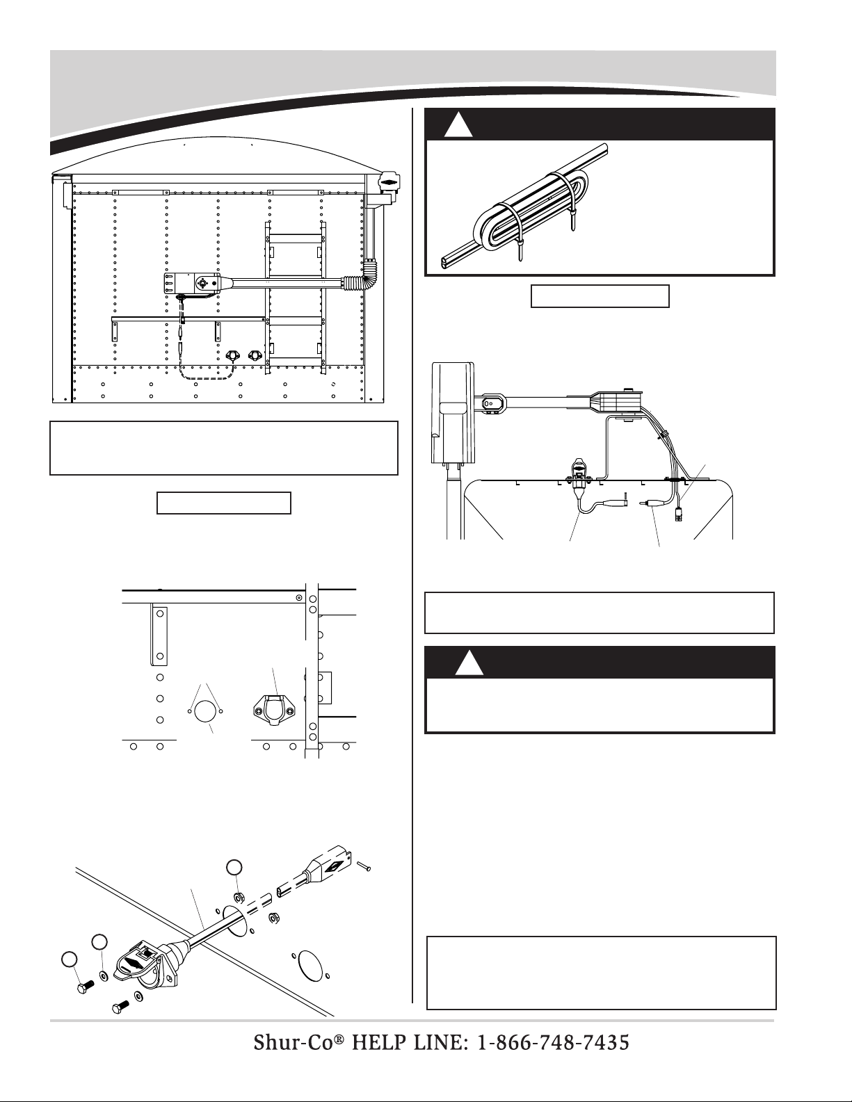
STEP 1:
Connect SMARTwire™ from electric motor to SMART-
wire™ from dual-conductor and secure connection with
lock pin.
Secure all wires to trailer with cable clips and
screws. If needed, use cable ties.
NOTE: Coat each connection with dielectric grease (P/N
1704378) to prevent corrosion.
STEP 2: Align socket over 2" hole. Using holes in anges on
socket as guide, mark and drill two 5/16" holes.
drill two
5/16" holes
7-pole
conductor
drill 2" hole
STEP 1: Locate dual-pole conductor socket near 7-pole con-
ductor socket as shown. Determine location and drill
2" hole through trailer skin.
STEP 3: Fasten conductor socket to trailer with 5/16" x 3/4"
cap screws, at washers and nuts.
smartwire™
smartwire™
from motor
smartwire™ from
dual-conductor socket
NOTE: Wire lengths are predetermined. Before installing
SMARTwire™ components, review and conrm wire routing
so wires reach components with ample room for
connection.
WIRING SCHEMATIC
DUAL CONDUCTOR
B
U
front of trailer
b
secure
w/cable
tie
NOTE: Release switch at end of cycle or modied-reset
circuit breaker will trip. After breaker resets, switch will
activate motor again. To reduce unnecessary strain on tarp
components, release switch at end of each cycle.
OPERATION:
A) Check motor direction by activating switch to OPEN. If switch
is running system backwards, change wire leads on dual-con-
ductor plug to opposite connections.
B) Close tarp: Push switch to CLOSE and hold. Observe tarp
and release switch when tarp is fully closed.
C) Open tarp: Push switch to OPEN and hold. Observe tarp
and release switch when tarp is fully open.
Other manuals for 4500 HD Series
3
Table of contents
Other Shurco Automobile Accessories manuals


Popular Automobile Accessories manuals by other brands


ULTIMATE SPEED
ULTIMATE SPEED 279746 Assembly and Safety Advice

SSV Works
SSV Works DF-F65 manual

ULTIMATE SPEED
ULTIMATE SPEED CARBON Assembly and Safety Advice

Witter
Witter F174 Fitting instructions

WeatherTech
WeatherTech No-Drill installation instructions

TAUBENREUTHER
TAUBENREUTHER 1-336050 Installation instruction