manuals.online logo
Brands
  1. Home
  2. •
  3. Brands
  4. •
  5. Shure
  6. •
  7. Microphone
  8. •
  9. Shure 527B User manual

Shure 527B User manual

Other Shure Microphone manuals

Shure SM27-LC User manual

Shure

Shure SM27-LC User manual

Shure MV5C User manual

Shure

Shure MV5C User manual

Shure Beta 91 User manual

Shure

Shure Beta 91 User manual

Shure MXA710 Series User manual

Shure

Shure MXA710 Series User manual

Shure KSM44A User manual

Shure

Shure KSM44A User manual

Shure 545D User manual

Shure

Shure 545D User manual

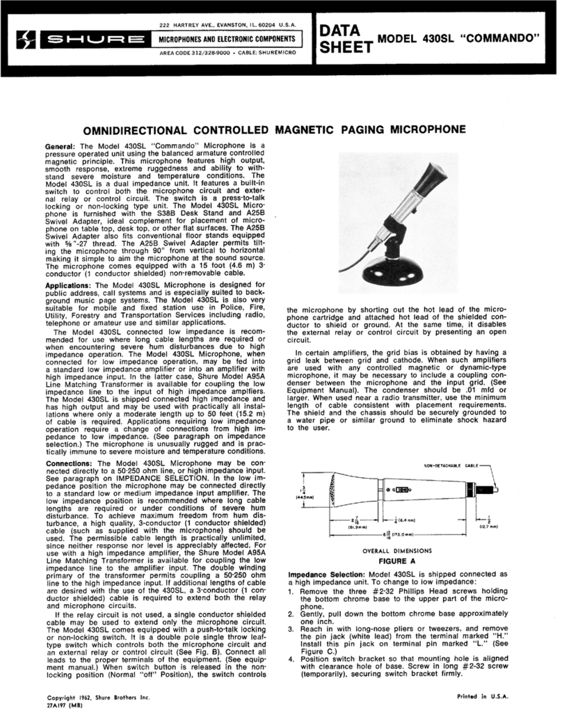
Shure Commando 415 User manual

Shure

Shure Commando 415 User manual

Shure 588SDX User manual

Shure

Shure 588SDX User manual

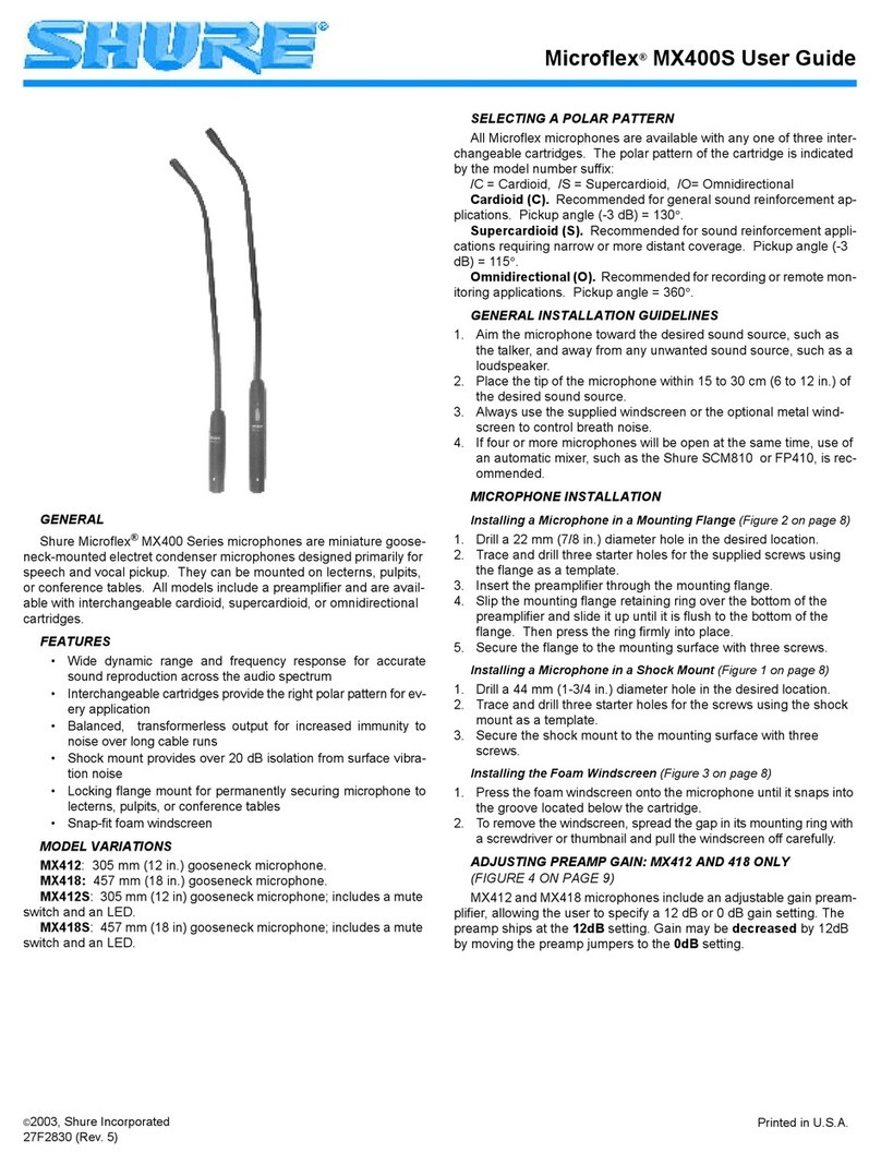
Shure Microflex MX405 User manual

Shure

Shure Microflex MX405 User manual

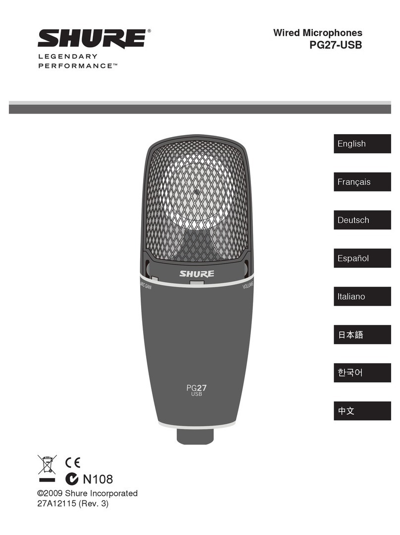
Shure PG27-USB Installation guide

Shure

Shure PG27-USB Installation guide

Shure 577B User manual

Shure

Shure 577B User manual

Shure R174 User manual

Shure

Shure R174 User manual

Shure Microflex MX418D User manual

Shure

Shure Microflex MX418D User manual

Shure Microflex MX415 User manual

Shure

Shure Microflex MX415 User manual

Shure C-Series User manual

Shure

Shure C-Series User manual

Shure BG 4.1 User manual

Shure

Shure BG 4.1 User manual

Shure M688 User manual

Shure

Shure M688 User manual

Shure SM57 User manual

Shure

Shure SM57 User manual

Shure Microflex MX400 Series User manual

Shure

Shure Microflex MX400 Series User manual

Shure 527B User manual

Shure

Shure 527B User manual

Shure PGA 98D User manual

Shure

Shure PGA 98D User manual

Shure UNI- DYNE B 15SB-GI8 User manual

Shure

Shure UNI- DYNE B 15SB-GI8 User manual

Shure PG Alta Series User manual

Shure

Shure PG Alta Series User manual

Shure PE15H-LC User manual

Shure

Shure PE15H-LC User manual

Popular Microphone manuals by other brands

Betzold 760932 operating instructions

Betzold

Betzold 760932 operating instructions

JTS UF-10TH/12 instruction manual

JTS

JTS UF-10TH/12 instruction manual

Sony ECM-Z200 Service manual

Sony

Sony ECM-Z200 Service manual

Electro-Voice 652 engineering data

Electro-Voice

Electro-Voice 652 engineering data

mantona 21150 instruction manual

mantona

mantona 21150 instruction manual

Loewe We. SEE 55 user manual

Loewe

Loewe We. SEE 55 user manual

IK Multimedia iRig Stream MIC PRO user manual

IK Multimedia

IK Multimedia iRig Stream MIC PRO user manual

DAPAudio RM-101 user manual

DAPAudio

DAPAudio RM-101 user manual

AKG CHM 21 User instructions

AKG

AKG CHM 21 User instructions

Sennheiser evolution wireless series EM 100 instruction manual

Sennheiser

Sennheiser evolution wireless series EM 100 instruction manual

Sony C-48 operating instructions

Sony

Sony C-48 operating instructions

GIGAMEDIA GGM PAMICUHFG user manual

GIGAMEDIA

GIGAMEDIA GGM PAMICUHFG user manual

auna PRO MIC-900 manual

auna PRO

auna PRO MIC-900 manual

AKG D 3800 User instructions

AKG

AKG D 3800 User instructions

MAIIN SOUND IIN style instruction manual

MAIIN SOUND

MAIIN SOUND IIN style instruction manual

Earthworks TC25 user manual

Earthworks

Earthworks TC25 user manual

Sonova Phonak Roger Series manual

Sonova

Sonova Phonak Roger Series manual

Alesis MicLink Wireless user guide

Alesis

Alesis MicLink Wireless user guide

manuals.online logo
manuals.online logoBrands
  • About & Mission
  • Contact us
  • Privacy Policy
  • Terms and Conditions

Copyright 2025 Manuals.Online. All Rights Reserved.

MODEL 527B
Dynamic Communications Microphone
The 527B microphone is an extremely reliable dy-
namic hand-held microphone with an extended low- and
high-frequency response particularly suited to ham radio
use, mobile FM transmission, and top-quality paging sys-
tems.Themicrophonehasaclear,crisp,andnaturalvoice
reponse. It features professional design, small size, light
weight, and modular construction.
Themodularconstructionofthe527Baccountsforits
tremendous ease of field serviceability. The cartridge,
switch, and cable are a modular design, which makes
them easily replaceable. The microphone is wired so that
the wires will not crimp or break.
Theunitfitsnaturallyand comfortably in thehandand
is not affected by heat or humidity. The exclusive
ARMO-DURRcase is immune to oil, grease, fumes, salt
spray, sun, rust, and corrosion and is outstanding in its
abilitytowithstandmechanicalshocksandvibrations.The
“Million-Cycle” leaf-type switch is double-pole, single-
throw, designed to withstand severe operating conditions
and constant usage.
30 mm
36.5 mm
4.7 mm 34.5 mm
10.3 mm
9.5 mm
9.1 mm
(23/64 IN.)
(3/8 IN.)
(1 13/16 IN.)
(1-7/16 IN.)
(3/16 IN.) (1-23/64 IN.)
(13/32 IN.)
MOUNTING HOLES,
CLEARANCE FOR
No. 8 SCREWS
MOUNTING BRACKET
FIGURE 1
Features
D
Extended low- and high-frequency reponse
D
Highly intelligible voice reponse
D
Unparalleled ruggedness and reliability
D
Moving coil (dynamic) element
D
ARMO-DUR case
D
“Million-Cycle” leaf-type switch controlling micro-
phone and external relay or switching circuits
D
Modular construction for easy field service
D
“Lifetime” hang-up button and mounting bracket
D
Long-life neoprene-jacketed coil cord
APPLICATIONS
The 527B microphone is highly recommended for all
types of mobile communications, ham radios, industrial
and commercial paging systems, outdoor public address
systems. The 527B is a low-impedance microphone and
is recommended where long cable lengths are required.
INSTALLATION
A mounting bracket for permanent installation is sup-
plied with each microphone. The bracket has mounting
holes with clearance for No. 6 or No. 8 screws (see
Figure 1).
CONNECTIONS
The internal switch connections of the 527B are
shown in Figure 2. The 527B has a four-conductor, coiled
cord cable and a double-pole, single-throw, leaf-type
switch to control the microphone circuit and an external
relay or switching circuit. The WHITE and GREEN leads
are the audio conductors for balanced-line connection to
the microphone circuit; the shield is connected to the mi-
crophone circuit ground. The microphone circuit of the
switchisnormallyopen,butcaneasilybemodifiedfornor-
mally shorted operation.
CARTRIDGE SWITCH CABLE
BLACK
RED
GREEN
WHITE
BLACK
BUTTON MOVEMENT
+
INTERNAL CONNECTIONS
FIGURE 2
Shure Brothers Incorporated
222 Hartrey Avenue
Evanston IL 60202-3696 U.S.A.
Model 527B User Guide
27A2083 (SF)
E1998, Shure Brothers Incorporated Printed in U.S.A.
INPUT TYPE WIRE
COLOR FUNCTION XLR
CONNECTOR 1/4 IN.
PHONE
PLUG
WHITE AUDIO + PIN 2 TIP
BALANCED GREEN AUDIO – PIN 3 RING
SHIELD CHASSIS GROUND PIN 1 SLEEVE
CABLE-TO-CONNECTOR WIRING
TABLE 1
The 527B is wired for balanced-line operation and is
recommended for use where long cable lengths are re-
quired,orconditions where severe hum pickup mayexist.
The 527B microphone can be fed directly into a standard
low-impedance amplifier, or a Shure A95 Series Line
Matching Transformer can be used for coupling the 527B
totheinputofahigh-imedanceamplifier. A two-conductor
shielded cable can be used for extending only the micro-
phone circuit. If both the microphone circuit and the re-
mote circuit are to be extended, a four-conductor cable
having two shielded conductors for the microphone
should be used.
The microphone circuit of the 527B is normally open
when the microphone switch button is in the normal posi-
tion.Themicrophoneswitchmayberewiredtohaveanor-
mally shorted microphone circuit. To modify the 527B for
a normally shorted circuit, proceed as follows:
1. RemovethethreeNo.6Phillipsself-threadingscrews
from the back of the microphone case.
2. Separate the case front and back, then remove the
microphone switch button.
3. Unsolderorclip the WHITE cable lead from the upper
(from the bottom of the microphone) switchsolder lug
(see Figure 2).
4. Solder the WHITE cable lead to the lower switch sol-
der lug (containing the YELLOW lead to the micro-
phone cartridge).
5. Place the microphone switch button in the normal
position on the case front. Place the case back on the
case front and firmly press the two sections together.
Fastenthecasebacktothecasefrontwiththescrews
previously removed.
OPERATION
The 527B will operate satisfactorily under all ordinary
conditionsofhumidity,heat,andcold.Droppingthemicro-
phone or other severe mechanical shocks should be
avoided.
SPECIFICATIONS
Type
Dynamic
Frequency Response
300 to 5,000 Hz (see Figure 3)
0
+10
9876543298765
FREQUENCY IN HERTZ
20000100001000
432
100
–10
5020
RELATIVE RESPONSE IN dB
TYPICAL FREQUENCY RESPONSE
FIGURE 3
Output Level (at 1,00 Hz)
Open Circuit Voltage* –33 dB. . . . . . . . . . . . . . . . . . .(22 mV)
Power Level** –52 dB. . . . . . . . . . . . . . . . . . . . . . . . . .
*0 dB = 1 V per 100 µbars
**0 dB = 1 mW per 10 µbars
Impedance
Microphone rating impedance is 150 Ω(200 Ω
actual) for connection to microphone inputs rated at
19 to 300 Ω
Switch
Double-pole, single-throw, leaf-type
Cable
Attached, 1.8 m (6 ft), 4-conductor (2 shielded),
neoprene-jacketed
Dimensions (See Figure 4)
3.688 in.
[9.37 cm]
1.765 in.
[4.48 cm]
.375 in.
[.95 cm]
.750 in.
[1.91 cm]
.093 in.
[.24 cm]
.062 in.
[.16 cm]
.032 in.
[.08 cm]
2.625 in.
[6.67 cm]
OVERALL DIMENSIONS
FIGURE 4
Net Weight
337 g (11.9 oz)
Packaged Weight
535 g (18.8 oz)
FURNISHED ACCESSORY
Mounting Bracket (3 in kit) RK6MB. . . . . . . . . . . . . .
REPLACEMENT PARTS
Cartridge R131. . . . . . . . . . . . . . . . . . . . . . . . . . . . . . . .
Switch RK319S. . . . . . . . . . . . . . . . . . . . . . . . . . . . . . . .
Cable C29C. . . . . . . . . . . . . . . . . . . . . . . . . . . . . . . . . .