Model 527C User Guide
©2005 Shure Incorporated
27C2084 (Rev. 5)
Printed in U.S.A.
Transistorized Dynamic Hand-Held Microphone
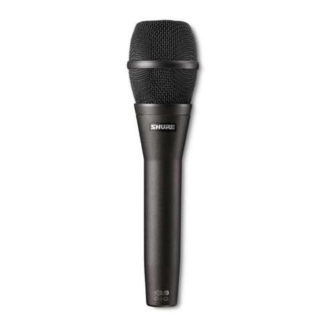
The Shure Model 527C is a dynamic hand-held communica-
tions microphone for use in a variety of mobile and fixed-station ap-
plications, including police, transportation, amateur radio and
similar applications. The 527C offers extremely low sensitivity to
hum pickup and low susceptibility to radio-frequency interference.
A built-in solid state amplifier permits the use of up to 30 m (100 ft)
of unshielded cable. The modular construction of the 527C allows
the cartridge, switch, and cable to be replaced in a matter of min-
utes, if necessary. The 527C fits naturally and comfortably in the
hand and is not adversely affected by heat or humidity. The
ARMO-DUR®case is immune to oil, grease, fumes, salt spray,
sun, rust and corrosion, and is outstanding in its ability to withstand
mechanical shocks and vibration.
FEATURES
•Built-in amplifier
•Frequency response from 300 to 5,000 Hz, tailored for voice
communications
•Low sensitivity to hum
•Low susceptibility to radio-frequency interference
•“Million-Cycle” leaf-type switch stands up under severe oper-
ating conditions and constant use
•High-impact ARMO-DUR®case—lighter and stronger than
die-cast metal, comfortable to the touch in hot or cold weather
•Rugged and dependable under all operating conditions
•Long-life neoprene-jacketed coil cord
CONNECTIONS
A typical external operating circuit is shown in Figure 1. Circuit
parameters such as supply voltage, load, current and sensitivity
may be selected using the curves shown in Figures 3 and 4. If, for
instance, the available supply voltage is 16 Vdc and a current drain
of 4 mA is desired, a load resistance (RL) of 2.2KΩis necessary.
With a supply voltage of 16 Vdc and a load resistance of 2.2KΩ, the
relative sensitivity is approximately +8 dB, or –3 dB output level ref-
erenced to the specified output level of –11 dB with 10 Vdc and a
470Ωload.
CABLE-TO-CONNECTOR WIRING
TABLE 1
TYPICAL OPERATING CIRCUIT
FIGURE 1
CAUTION:
To avoid damage to the 527C, observe the following:
•
Supply voltage (V) must be between 4 and 35 Vdc. Voltages ex-
ceeding 35 Vdc may substantially reduce the life of the micro-
phone. Voltages below 4 Vdc are not sufficient for microphone
amplifier operation (although no damage will occur).
•
Do not exceed the maximum allowable current (dissipation lim-
it) for the various combinations of supply voltages and load re-
sistances.
•
Maintain proper polarity for the red (+) and black (–) leads as
shown in Figure 1.
WIRE COLOR FUNCTION
BLACK AUDIO GROUND
RED AUDIO
GREEN
RELAY CIRCUIT
WHITE
AUDIO
OUTPUT
TRANSMIT
RELAY
CIRCUIT
LOAD RESISTANCE
RL
5F
RED (+)
AMPLIFIER
CARTRIDGE
MICROPHONE
BLACK (–)
GREEN
WHITE
SWITCH
+SUPPLY
VOLTAGE
VS
5
