Shure SM81 User manual

Model SM81 User Guide
Shure
Brothers Incorporated
222 Hartrey A
venue
Evanston IL 60202-3696 U.S.A.
27A2916
(P
A)
1996, Shure Brothers Inc.
Printed in U.S.A.
MODEL SM81
UNIDIRECTIONAL CONDENSER MICROPHONE
The Shure Model SM81 is a high-quality, unidirectional
condenser
microphone designed for the
most demanding pro
-
fessional applications in studio recording, broadcasting, and
sound
reinforcement. It is especially suitable
for applications re
-
quiring
extremely wide frequency
response, low noise and dis
-
tortion characteristics, very low RF susceptibility, and reliable
operation over a wide range of temperature and humidity
extremes.
The case is constructed
of steel for ruggedness, with
a stainless steel screen, and finished in durable vinyl paint.
The microphone is furnished with a swivel adapter, atten-
uator lock, windscreen, and carrying/storage case. It is sup-
plied
without cable. A
vailable accessories are a highly ef
ficient
pop-filter
grille (Model A81G), a heavy-duty windscreen (Model
A81WS), a compact, lightweight microphone stand (Model
S15)
capable of extension to 4.3 m (14 ft), a versatile stereo mi
-
crophone
adapter (Model A27M), and a dual-channel phantom
power supply (Model PS1A). An alternative omnidirectional
cartridge (Model R104A) is also available.
Model SM81 Features:
•
Wide-range, frequency response for exceptionally accu-
rate recording and sound reinforcement applications
•
Low noise and high output clipping level characteristics
•
Low distortion characteristics over the entire audio spec-
trum for a wide range of load impedances
•
Cardioid polar pattern, uniform with frequency and sym-
metrical about axis, to provide maximum rejection and
minimum coloration of off-axis sounds
•
Very low RF susceptibility
•
Selectable
low-frequency response: flat, 6 or 18
dB/octave
rolloff
•
10 dB attenuator accessible without disassembly; lockable
in either position
•
Wide-range phantom powering includes DIN 45 596 volt-
ages of 12 and 48 Vdc
•
Rugged construction for outstanding reliability
•
Field-usable
over wide range of temperature and
humidity
conditions
SPECIFICATIONS
Type
Cardioid
Frequency Response
20 to 20,000 Hz (see Figure 1)
TYPICAL FREQUENCY RESPONSE
FIGURE 1
Polar Pattern
Cardioid
(unidirectional) response—uniform with frequen
-
cy, symmetrical about axis (see Figure 2)
TYPICAL
POLAR P
ATTERNS
FIGURE 2
Output Impedance
Rated at 150 ohms (85 Ωactual)
Recommended minimum load impedance: 800 Ω(May
be used with loads as low as 150 Ωwith reduced clip-
ping level)
Output
Level (at 1,000 Hz)
Open Circuit Voltage –65 dB (0.56 mV).
. . . . . . . . . . . . . . . .
(0 dB = 1 volt per µbar)
Equivalent Power Level –40.5 dB.
. . . . . . . . . . . . . . . . . . . . .
(0 dB = 1 milliwatt per 10 µbars)
Clipping
Level (at 1,000 Hz)
800 ΩLoad –4 dBV (0.63 V).
. . . . . . . . . . . . . . . . . . . . . . . . .
150 Ω
Load
–15 dBV (0.18 V).
. . .
. . . . . . . . . . . . . . . . . . . .

2
T
otal Harmonic Distortion
Less than 0.5% (131 dB SPL at 250 Hz into 800 Ω
load)
Maximum
SPL (at 1,000 Hz)
136 dB (attenuator at 0); 146 dB (attenuator at 10)
with 800 Ω
load
128 dB (attenuator at 0); 138 dB (attenuator at 10)
with 150 Ω
load
Hum
Pickup
–3 dB equivalent SPL in a 1 moe field (60 Hz)
Output
Noise
(equivalent sound pressure levels; measured
with true rms voltmeter)
16 dB typical, A-weighted
19 dB typical, weighted per DIN 45 405
Signal-to-Noise Ratio
78 dB (IEC 651)* at 94 dB SPL
Overvoltage
and Reverse Polarity Protection
Max. External V
oltage Applied
to Pins 2 and 3 with Respect to Pin 1 + 52 Vdc.
. . . . . . .
Reverse Polarity
Protection 200 mA max. (diode-clamped).
. . . . . . . . . . . . .
Phasing
Positive pressure on diaphragm produces positive voltage
on pin 2 relative to pin 3
Cartridge
Capacitance
54 pF
LP
Response Switch
Flat,
–6 dB/octave below 100 Hz, –18 dB/octave below 80
Hz
Attenuator
Switch
0 or 10 dB (120 pF)
Power
Supply V
oltage
11 to 52 Vdc, positive pins 2 and 3.
. . . . . .
Current Drain 1.0 mA to 1.2 mA.
. . . . . . . . . . . . . . . . . . . . . .
Environmental Conditions
Relative Humidity 0–50%
– 29
to 74C.
. . . . . . . . . . . . . . .
(–20to 165F)
Relative Humidity 0–95%
– 29
to 57C.
. . . . . . . . . . . . . .
(–20to 135F)
Connector
Professional 3-pin audio**
Case
Steel
construction with metallic vinyl paint finish and stain
-
less steel screen
Dimensions
See Figure 3
OVERALL DIMENSIONS
FIGURE 3
Weight
Net 230 grams (8 oz).
. . . . . . . . . . . . . . . . . . . . . . . . . . . . . . .
Packaged 1.2 kg (2 lb 10 oz).
. . . . . . . . . . . . . . . . . . . . . . . . .
*S/N
ratio is dif
ference between microphone
output at 94 dB SPL and micro
-
phone
self-noise A-weighted.
**Designed
to mate with Cannon XL series,
Switchcraft A3 (Q.G.) series or
equivalent
connectors.
Certification
Conforms
to European Union directives, eligible to bear
CE
marking;
meets European Union EMC Immunity Requirements
(EN 50 082–1, 1992); RF radiated (IEC 801–3); ESD (IEC
801–2); EFT (IEC 801–4).
OPERATION
The SM81 is designed for phantom powering by Shure
Model
PS1A Power Supply
, or by virtually any microphone pow
-
er supply providing 12 to 48 Vdc phantom voltage.
Use only high-quality cables, as intermittent shorts be-
tween
broken shield wires and balanced
conductors will cause
extremely large noise transients in the system. Avoid ground
loops
due to grounded connector shells or the microphone case
touching other grounded metal objects. Follow generally ac-
cepted audio grounding practices.
Paralleling or “Y-ing” the SM81 with another microphone
(two microphones on the same input) is not recommended;
separate inputs are preferable. However, paralleling two
SM81’s may be accomplished with either a reduction in maxi-
mum
SPL and output level, or a reduction only in
output level if
the microphones are electrically isolated. With the micro-
phones
paralleled either before or
after a PS1A Power Supply
,
the
maximum SPL is reduced by approximately 10
dB and the
output level by 6 dB. The reduction in maximum SPL can be
avoided by using either two Shure A15AS Attenuators and a
Switchcraft 391Q43 Y-Adapter to isolate the microphones, or
an
isolation network as shown in Figure 4. The network
reduces
each microphone output level by 8 dB, while the A15AS re-
duces
the output level by 5 dB plus the attenuator
’
s 15, 20, or 25
dB (switch-selectable). The network or attenuators can be in-
serted between the power supply outputs and mixer input, or
between two microphones and a single power supply input.
Note
that a PS1A Power Supply can power two SM81’
s on each
input;
other power supplies should be checked to see if they can
supply
a minimum of 10 Vdc at each microphone when both mi
-
crophones are connected.
A
minimum load impedance of 800
Ω
or greater should be
used
for maximum signal handling and minimum distortion. The
load
may be as low as 150
Ω
, but a reduction in output
clipping
level will result. It should be noted that the power supply itself
may
add loading (3300
Ω
in the Shure PS1A power supply) to
the microphones.

3
FROM
MIC
1
FROM
MIC 2
OUTPUT
1
2
3
1
23
1
23
ALL RESIST
ORS
232
Ω
, 1%
ISOLATION NETWORK
FIGURE 4
PS1A
POWER SUPPL
Y
Connect
the microphone cable to the SM81 and the power
supply MICROPHONE connector
. The power supply uses the
balanced
audio cable pair to carry the supply current to the mi
-
crophone, and the cable shield as a ground return.
Connect the power supply OUTPUT connector to a low-
impedance microphone input of the mixer, audio console or
tape recorder. A second SM81 may be connected to the re-
maining power supply channel in a similar manner.
ALTERNATE
POWER SOURCES
As
an alternate to the PS1A
power supply
, the SM81 may
be
phantom powered from virtually any mixer
, audio console or
tape recorder using one of the wiring configurations shown in
Figures
5 and 6. Any well-filtered voltage available in the mixer
from
12 to 48 Vdc may be used. The graph in Figure 7 shows the
range of values which can be used for resistor R when the
SM81
is used with a regulated power supply
. The tolerance of
the resistors (2R) shown in Figure 5 should be 1% or better to
assure close matching, although the absolute value is not
12
3
OUTPUT
TO
MIXER
2R
2R
B+
INPUT FROM
MICROPHONE
TWO-RESISTOR CONFIGURATION
FIGURE 5
12
3
OUTPUT
TO
MIXER
INPUT FROM
MICROPHONE
B+
R
CT
CENTER-TAPPED TRANSFORMER
CONFIGURATION
FIGURE 6
RESISTOR R VALUES
FIGURE 7
critical.
Note that the two-resistor phantom power supply (Fig
-
ure
5) presents a load equal to 4R, paralelled with the mixer in
-
put
impedance, to the SM81.
If the combined parallel load is be
-
low 800 Ω, the transformer configuration (Figure 6) is
recommended,
and if the combined load is 150
Ω
or less, it must
be used.
If the power supply is unregulated, the power supply volt-
age
may drop when the SM81 is connected to
it, due to the add
-
ed
load. T
o account for this load, the value of R may be deter
-
mined as follows. Connect a variable resistance tor resistor
substitution
box) in series with a 10 k
Ω,
10% resistor
. Connect
the
free end of the 10k resistor to ground and the free
end of the
variable
resistor to
B + of the power supply
. Adjust the variable
resistor
until 12 to 36 volts is measured across the 10k resistor
.
Note the actual DC supply voltage and the value
of the variable
resistor. Verify that the resistor value falls within the indicated
range
on the graph of Figure 7. The value of the variable resistor
is the appropriate resistance R for use in Figure 6. If the configu
-
ration
in
Figure 5 is to be used, double the resistor value (2R).
Voltages
as low as 10 Vdc minimum as measured at the micro
-
phone
connector are acceptable. The nominal current drain at
10 Vdc is 1.1 mA. This is the minimum current a power supply
must be able to deliver for properoperation.
For
example, in mixers with 30
Vdc power supplies, the val
-
ue
of 2R for the configuration in Figure 4 could be 3.6 k. T
wo 3.6
k
resistors should be closely matched
(2% or better), and may
be mounted externally with the B+ end connected to the 30 V
terminal. The resistors may also be mounted internally (such
modifications
should be performed by qualified service person
-
nel only).
A
convenient method of battery-powering the SM81 using
two 9 volt batteries is shown in Figure 8. Note that this circuit

4
12 3
OUTPUT
TO
MIXER
INPUT FROM
MICROPHONE
12
3
IN
914
OR IN 4148
2000
9V
– +
9V
– +
2000
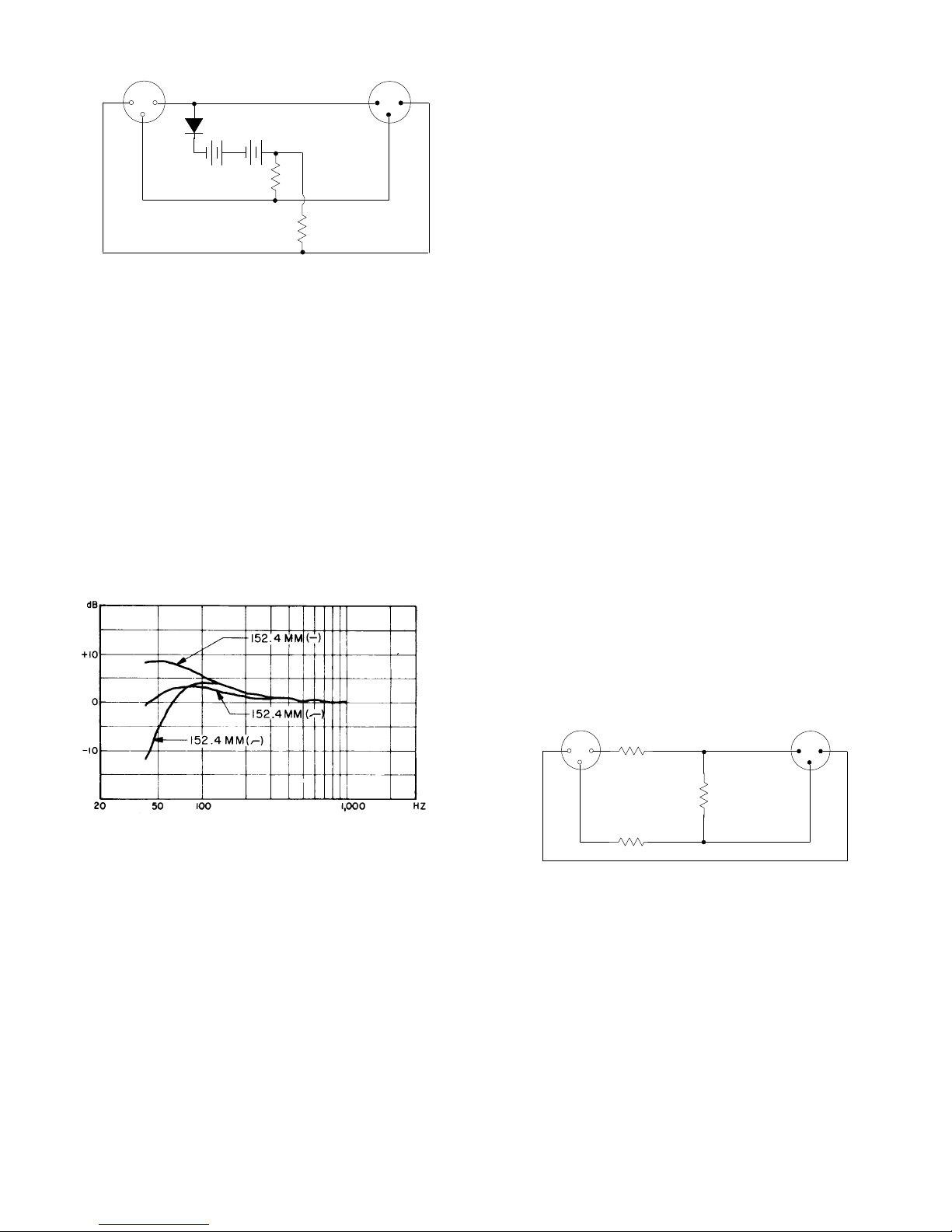
BATTERY POWER SUPPLY
FIGURE 8
can only be used with balanced, floating (ungrounded),
transformer-coupled input mixers such as the Shure M68A.
The
resistors should be 1% tolerance or better to assure
close
matching.
With new batteries, this supply will operate an SM81
for approx-imately 200 hours.
LOW-FREQUENCY
RESPONSE SWITCH
The SM81 has a three-position low-frequency response
switch
located on its handle. The switch
is recessed to avoid ac
-
cidental movement, but may be easily moved with the finger-
tips. The user may select either flat response, low-frequency
rolloff
of 6 dB per octave below 100 Hz,
or low-frequency cutof
f
of 18 dB per octave below 80 Hz (see Figure 1). When close-
miking instruments or vocalists, an increase in low-frequency
response
(proximity ef
fect) takes place. Figure 9 illustrates this
effect with the switch in all three positions. Note that the low
frequency response switch may be used to compensate for
proximity effect by selecting the desired low-frequency re-
sponse.
PROXIMITY EFFECT AND COMPENSATION
FIGURE 9
ATTENUATOR
RING
The
SM81 has a switchable 10 dB capacitive attenuator to
prevent
high sound pressure levels from overloading the micro
-
phone’s internal electronics. The attenuator is engaged by ro-
tating
the actuator ring
directly below the grille assembly
. In the
“10”
position, the output of the microphone is reduced by 10 dB,
increasing
the maximum sound pressure level at clipping by 10
dB. The
attenuator ring may be locked in either the “Q” or “10”
position
as
follows. Unscrew the grille and cartridge assembly
by
unscrewing counter-clockwise from the top. T
urn the
actua
-
tor
ring to the “0” or “10” position as desired. Insert the actuator
ring
lock (small clear piece of plastic) in the area
behind the ac
-
tuator
ring between the pin and the edge of the slot, thereby
pre
-
venting
the ring from
turning. Replace the grill and cartridge as
-
sembly.
The amount of attenuation can be increased by changing
the
value of the capacitor in the 10 dB attenuator switch assem
-
bly.
Note that this change must be done carefully and with sub
-
sequent cleaning to avoid possible signal-to-noise degrada-
tion. Unscrew the grille and cartridge assembly
(counterclockwise
from top). Lift
the 10 dB attenuator actuator
ring
up and over the
screw threads. Grasp the center contact of
the
10 dB attenuator
switch assembly and lift upward to remove
it. Obtain a 5% NPO monolithic ceramic capacitor (Centralab
MONO-KAP
CN series or equivalent) of the required value for
the desired attenuation
Attenuation Capacitance
–15 dB 270 pF
– 20 dB 560 pF
– 25 dB 1000 pF
– 30 dB 1800 pF
Using
long-nose pliers and a low-wattage, pencil-type sol
-
dering
iron, carefully remove the capacitor from the switch as
-
sembly
and replace it with the new value. T
ake care not to touch
the
switch assembly with the soldering iron. T
o remove possible
contamination,
after soldering wash the entire switch assembly
in
a mild detergent solution, rinse it in distilled water
, soak it in
alcohol
to remove the water
, and allow it to air dry
. Reassemble
the
SM81. Note the new attenuation value on the SM81 attenu
-
ator ring with a small label.
MIXER
OVERLOAD
The
SM81 output is about 15 dB higher than most dynamic
microphones, in order to provide optimum signal-to-noise ratio.
When used at moderate to high SPLs, this additional output
may
overload the mixer input. A resistive attenuator
can be in
-
serted in the microphone line ahead of the mixer to minimize
this. The Shure Model A15AS Attenuator (15, 20, or 25 dB
switch-selectable)
is specially designed for use with condenser
microphones.
A convenient 15 dB attenuator design is shown in
Figure 10. The resistors shown are 1
12-watt, 1%
tolerance,
and
the circuit may be packaged in a Switchcraft S3FM adapter
housing.
The 15 dB attenuator can be used between the SM81
and the PS1A (or other power supply), or between the PS1A
and
the mixer
. T
wo of these attenuators may be used in series
to provide 30 dB of attenuation. Note that commercially avail-
able
150
Ω
attenuators (such as the Shure
Model A15AS) are
not recommended, due to loading.
12
3
OUTPUT
TO
MIXER
INPUT FROM
MICROPHONE
1
23
412
412
215
15 DB ATTENUATOR CIRCUIT
FIGURE 10
WIND
NOISE
The excellent frequency response of professional con-
denser
microphones such as the SM81 makes them quite sen
-
sitive to wind, breath, and air currents from ventilation equip-
ment. The resulting low-frequency microphone output may
cause
mixer overload or other problems. The Model A81G Pop
Filter
Grille attenuates breath popping sounds when the micro
-
phone is close-talked, and permits its use outdoors with mini-
mal pickup of rushing and rumbling sounds.
Slip the A81G over the SM81 until the inside of the A81G
touches
the top of the microphone. T
ighten the A81G by rotat
-
ing
the knurled collar clockwise from the bottom. When remov
-
ing the A81G, loosen the knurled collar first (otherwise the car
-
tridge will unscrew with the A81G).
For outdoor use under very windy conditions, the Model
A81WS Heavy-Duty Windscreen is recommended.

5
BLOCK DIAGRAM
FIGURE 11
CAPACITOR
CARTRIDGE
FET
IMPEDANCE
CONVERTER
LF
RESPONSE
FILTER
CLASS
A
COMPOUND
AMPLIFIER
RFI
FILTER
BALANCED
TRANSFORMER
REGULATOR/
REVERSE
VOLTAGE
PROTECT
CAPACITIVE
ATTENUATOR
CIRCUIT
DESCRIPTION
A
block diagram of the SM81 is shown in Figure 1
1. The ca
-
pacitor cartridge is followed by a switch-controlled capacitive
attenuator stage which provides for 10 dB attenuation at the
cartridge output. The signal is fed to a field-effect transistor
(FET)
impedance
conversion stage. The FET output drives an
active
low-frequency response (high-pass) filter controlled by a
three-position switch. The filter output from a compound tran-
sistor, Class A, emitter-follower amplifier is transformer-
coupled,
providing a balanced output to the RFI protection filter
at the microphone connector. An active, constant-current
power supply circuit regulates the phantom voltage, allowing
the
SM81 to operate over a very wide range of voltages. A
re
-
verse
voltage protection diode guards against miswired cables
and
equipment. The circuit contains five
semiconductors to pro
-
vide low noise, low distortion, wide frequency response and
ultra-reliable
operation over a very wide range of operating con
-
ditions.
SERVICING
Troubleshooting
Due to the high packing density and circuit complexity of
the
SM81, only basic servicing is recommended. The following
steps should be taken if problems arise:
1. Check
the power supply output voltage to the
microphone.
For the Shure PS1A, this should be 21.5 ±1.5 Vdc open
circuit.
2. Check the voltage on microphone connector pins 2and 3
(at
back of connector; cable connector disassembled from
shell
but connected to microphone). The voltage at pins 2
and
3 with reference
to pin 1 should be between 10 and 48
Vdc.
3. If
more than one SM81 is available, interchange cartridge
assemblies
to determine whether the
cartridge or amplifier
is at fault.
Disassembly
The SM81 can be disassembled as follows:
1. Unscrew the grille and cartridge assembly (counterclock-
wise from top).
2. Lift the 10 dB attenuator actuator ring up and over the
screw threads.
3. Grasp
the center contact of the 10 dB attenuator switch as
-
sembly and lift upward to remove it.
4. Turn the slotted head screw near the plug counterclock-
wise (inward) as far as it will go. Using long-nose pliers,
grasp
one pin of the three-pin connector and withdraw the
RFI filter and plug element from the handle.
5. Remove
the low-frequency response switch
knob by plac
-
ing
a small screwdriver or tweezers
into the slot under the
ridge of the knob and lifting outward.
6. Remove
the small Phillips screw near
the plug. T
ap the car
-
tridge end of the handle
gently on a firm surface; the printed
circuit
board and support assembly will slide out of the car
-
tridoe end.
ARCHITECTS’
SPECIFICA
TION
The microphone shall be a condenser microphone with a
frequency
response of 20 to 20,000 Hz. It shall have a unidirec
-
tional pickup characteristic, with cancellation at the sides of 6
dB and a minimum cancellation at the rear of 15 dB at 1 kHz.
The
microphone
shall have a rated output impedance of 150
Ω
for
connection to microphone
inputs of 150 ohms or higher
. The
open circuit voltage shall be –65
dB (0.56 mV) (0 dB equals 1
volt per microbar).
The microphone shall contain a three-position low
frequency response switch and a lockable 10 dB attenuator
pad.The overall dimensions shall be 212 mm (8-11/32 in.) in
length
by 23.5 mm (15/16 in.) in diameter
. The handle diameter
shall
be 20.1 mm (25/32 in.). The weight shall be
230 grams (8
oz). The microphone shall be capable of being powered by a
phantom power supply with an output of 11 to 52 Vdc, or by a
mixer,
audio console or tape recorder capable of supplying 1
1 to
52 Vdc.
The microphone shall be a Shure Model SM81.
FURNISHED
ACCESSORIES
Swivel Adapter A57D.
. . . . . . . . . . . . . . . . . . . . . . . . . . . . . . .
10 dB Attenuator Lock 34A830.
. . . . . . . . . . . . . . . . . . . . . . . .
Carrying/Storage Case 65A1797.
. . . . . . . . . . . . . . . . . . . . . .
Windscreen RK311
. . . . . . . . . . . . . . . . . . . . . . . . . . . . . . . . . .
OPTIONAL
ACCESSORIES
Pop-Filter Grille A81G.
. . . . . . . . . . . . . . . . . . . . . . . . . . . . . . .
Heavy-Duty Windscreen A81WS.
. . . . . . . . . . . . . . . . . . . . . .
Tripod Microphone Stand (4.3 m [14 ftl) S15.
. . . . . . . . . . . .
Stereo Microphone Adapter A27M.
. . . . . . . . . . . . . . . . . . . . .
Cable (7.6m [25ft]) C25F.
. . . . . . . . . . . . . . . . . . . . . . . . . . . . .
Phantom Power Supply PS1A.
. . . . . . . . . . . . . . . . . . . . . . . .
Omnidirectional Cartridge R104A.
. . . . . . . . . . . . . . . . . . . . .
REPLACEMENT
P
ARTS
Cartridge and Grille Assembly
R104
.
. . . . . . . . . . . . . . . . . .
SERVICE STATEMENT
For
additional service
or parts information, please contact
Shure’s Service department at 1-800-516-2525. Outside the
United States, please contact your authorized Shure Service
Center.
Other manuals for SM81
4
Table of contents
Other Shure Microphone manuals

Shure
Shure PSM 200 User manual

Shure
Shure Microflex MX200 Series User manual

Shure
Shure Unisphere I PE56D-CN User manual

Shure
Shure VP83 User manual

Shure
Shure PSM 200 User manual

Shure
Shure Microflex MX202B/C User manual

Shure
Shure 708S Stratoliner User manual

Shure
Shure 202 User manual

Shure
Shure SM7B User manual

Shure
Shure WM98 User manual