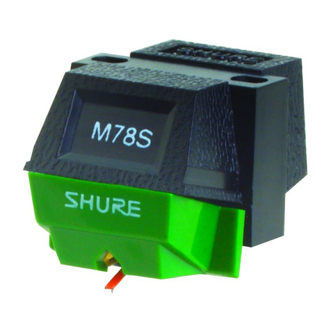
Shure ML140HE User manual


SPECIFICATIONS
Frequency Response
20 to 22,000 Hz
Output (at
1,000
Hz)
4.0 rnV per channel at 5 cmlsec peak recorded
velocity
Inductance
360 rnH
Dc Resistance
1,000 ohms
Optimum Load
47,000 ohms, 200 to 300 pF, includingtone arm wir-
ing and amplifier input circuitry
Channel Separation (minimum)
25 dB at 1 kHz, 15 dB at 10 kHz
Channel Balance
Within 2 dB
Tracking Force
Force at Stylus Total Tone Arm
Tip Setting
Optimum 1.0 gram 1.5 grams
Maximum 1.25 grams
1.75
grams
Force Exerted by Dynamic Stabilizer
0.5 grams
Typical Trackability (at 1 gram, in cmlsec peak
velocity) 400 Hz
-
29 cmlsec
1,000 Hz
-
42 cmlsec
5,000 Hz
-
60 cmlsec
10,000 Hz
-
50 cmlsec
Net Weight
4.5 grams
Replacement Stylus
NIIOHE, nude MASARTM-polishedhyperelliptical
diamond tip, 5
x
3Bp (.0002 x ,0015 in.),
MICROWALUBeTMberyllium shank
2

BIFOLD-PARAFLUX Coil Core
Interlocking
The
cartridge body
of the
ML140HE
contains
an abundance of new functional electrical
featuresfor highoutput with maximumfidelity.
a
The BIFOLD-PARAFLUX coil-core has
prealigned two-layer folded pole pieces
with parallel flux laminations to provide
greater efficiency of energy transfer and
maximumchannel separation. The result is
superb stereo imaging and depth.
w
The architecture of the internal frame in-
terlocks to produce a completely rigid,
nonresonant substructure. The cartridge
body will never wear out or cause deteriora-
tion of the sound.
a
The true humbucking coil configuration
results in maximum hum cancellation.
a
The noncorroding gold-plated terminal pins
ensure continuity of the signal path.

The Dynamic Stabilizer has been newly design-
ed to maintain the traditionally distinguished
Shure effectiveness in overcoming real-world
warp, static, and dust obstructions to record-
playing accuracy.
w
The Stabilizer's viscous-damping reduces
warp and tone arm resonance effects to in-
significance. The newly designed miniature
pivot system acts like a shock absorber to
prevent groove skipping, mistracking, and
distortion caused by record warps.
,
."ANLNF
DST'NIC
,---i,
"
hC,W?>
~
m,.,
----
--I
-__-=-
p-p~--lbzT-:
!~-
-===&L
OTHER CARTRIDGE
L<>b\TAUT 085TaNcE
-
pppp-
~
-;-~--7-
ML140HE
The electrically conductive Stabilizer fibers
remove static charges from the record sur-
face and conduct them to ground to
eliminate static charge noise and minimize
the attraction of dust tothe record surface.

More than
10,000
tiny fibers in each
Stabilizer reach down into the groove to
sweep away interfering and abrasive dust
and grit. Records stay cleaner and noise
free longer.
Functioning like a shock absorber, the
Stabilizer protects the stylus from damage
if it isaccidentally dropped on the record.
The unique Shure
SIDE-GUARD
protects the
stylus from accidental damage caused by im-
pacts from the side, such as when the tone
arm slides across the record.

The elements
of
the stylus
have been
meticulously optimized for low effective mass,
continuity of groove contact, and accurate
duplication of intricate groove modulations.
The result is a cartridge with excellent sound
clarity that enhances the enjoyment of listen-
ing to records. Three features of the design
provide this exceptional performance.
m
The ultra-thin wall beryllium shank
com-
bines an ideal configuration with an ideal
material. Beryllium is extremely light, yet
highly rigid. Shure has developed a unique
fabrication method, called MICRO-
WALLIBeTM,that forms the shank into a
thin-wall tube of 13p-thick
(.0005
inches)
beryllium. This yields the highest ratio of
stiffness to density of various attainable
shank materials and configurations. We
call this ratio the Shank Performance Ratio
(SPR); higher numbers mean improved per-
formance, especially in high-frequency
trackability. To the listener it means that
the onset of complex difficult-to-play
sounds, such as trumpets, pianos, female
vocalists, and full orchestras, will sound
truer and will be cleanly reproduced.

Below are shown various possible beryllium
shank structures, and the SPR of each.
MlCROWALLlBe is clearly superior.
BERYLLIUM SHANKS:
SHANK PERFORMANCE RATIOS
Solid Rod:
Thick
Wall Tube: MICROWALLIBeTM
10
mil dla.
2
mll wall;
0.5
mil wall;
12 m~ldia.
18
mil d~a.
1.00 SPR* 2.06 SPR* 6.25 SPR'
'SPR: Stiffnessldenslty relative to
10
mll diameter solid
rod

w
The hyperelliptical tip geometry has an op-
timized tip-groove contact area that
dramatically reduces both harmonic and in-
terrnodulation distortion. The result is
crisp, precise sound throughout the entire
record.
ELLIPTICAL HYPERELLIPTICAL
TIP SHAPES
rmn
2nd harmonic dlstortlon, average both channels
3.7
kHz, 31 cmlsec peak recorded veloclty
99%
IM
dlsiortlon, average both channels
1 kHzll.5
kHz,
15 cmlsec peak recorded velocity
6mll 2xim81 Zx15m11
Sphei8cai
Elllplical Hy~erell8~f8cal

The ~?i~~~~~-~olishedcontact areas
of the
tip decrease groove abrasion. Records last
longer and stay quieter.
NOISE BAND WIDTH: 500Hz
TO
20
kHz
MEDIUM: LACQUER MASTER
LACQUER GROUP
1
PLAYED
BY
UNWORN
CONVENTIONAL
STYLUS
7
LACQUER GROUP
2
PLAYED
BY
UNWORN
MESAR
STYLUS
1234567891011
NUMBER OF PLAYS

FREQUENCY RESPONSE, TRACKABILITY,
AND HIGH FIDELITY
Performance is the ultimate test of success
for any cartridge design.
Frequency response
and
trackability
specifications are two of the
most important indicators of successful high-
fidelity performance.
Frequency response
demonstrates the ac-
curacy of reproduction of tones across the en-
tire audible spectrum.
A
flat frequency
response displays a cartridge's ability to
reproduce
all
sounds without emphasis or at-
tenuation. The tonal balance of low, mid, and
high pitchedsounds are reproduced exactly as
they were recorded.
Trackability
measures the ability of a stylus,
at a given tracking force, to maintain contact
with both groove walls while negotiating the
tortuouspeaks, valleys, andhairpinturns of to-
day's heavily modulated record groove.
A
car-
tridge must allow the stylus tip to stay in firm
contact with the groove walls to produce clear,
clean, undistorted sound, and to prevent
record groove damage that permanently alters
and distorts the sound.

An authentic high-fidelity cartridge MUST
have a
flat
frequency response
and high
trackability
at a very low tracking force. THE
ML140HE MEETS THESE CRITERIA. Its fre-
quency response isessentially flat from 20 Hz
to 22,000 Hz. At a tracking force of 1 gram, it
typically tracks signals of the following
velocities (in cmlsec peak recorded velocity):
400 Hz
-
29 cmlsec
1,000 Hz
-
42 cmlsec
5,000 Hz
-
60 cmlsec
10,000 Hz
-
50 cmlsec
The final test of performance is operation
under less than ideal real-world conditions.
The Dynamic Stabilizer prevents interference
from record warp, arm resonance, shock, and
dirt and dust; the SIDE-GUARD protects
against stylus damage. The ML140HE per-
forms flawlessly-it lets you listen to the
music!

INSTALLING THE CARTRIDGE
(see
page
20)
1.
Remove the stylus.
2. Make electricalconnections: right channel (R),red
lead; right ground (RG),green lead; left channel (L),
white lead; left ground (LG), blue lead.
3. Mount the cartridge:
A. In a headshell with unthreaded holes or slots.
0.
Ina headshell with threaded mounting holes.
4.
Cartridge Leveling: Check that the front and side
of the Alignment Stylus is parallel to a record on
the turntable. If necessary, insert spacers or a
shim, or rotate the headshell.
5. Overhang Alignment: Place the Overhang Gauge
over the turntable spindle, and adjust the position
of the cartridge in the headshell until the Align-
ment Stylus is parallel to the Gauge markings.
6.
Tracking Force: This cartridge is designed for an
optimum tracking force of 1.0 gram (1.25 grams
maximum). The viscous-damped Dynamic
Stabilizer exerts a force on the record of 0.5 grams
that must also be accommodated in the total tone
arm tracking force setting. Therefore, use the
following settings.
To obtain this force Set the arm tracking
at the stylus tip force adjustment to
Optimum 1.0 gram 1.5 grams
Maximum 1.25 grams 1.75 grams
To use an external gauge such as the Shure SFG-2
Stylus Force Gauge to set the tracking force, lock
the Dynamic Stabilizer "up", and set the tracking

force as shown in the second column. When the
Stabilizer rides on the record with the cartridge in
use, the extra
0.5
grams will be offset by the
Stabilizer and WILL NOT APPEAR AT THE
STYLUS TIP. The tip force will bethat shown inthe
first column.
If for any reason the cartridge is used with the
Stabilizer "up", the tracking force should beset as
recommended for the tip:
1.0
gram Optimum,
1.25
grams Maximum.
7.
Skating Compensation: Set the mechanism as
recommended by the tone arm manufacturer. Use
a skating compensation corresponding to the
total tone arm tracking force setting.
8.
Operation: Carefully place the Dynamic Stabilizer
in the "operating" position so that it floats below
the cartridge. The cartridge is now ready to use.
9.
Cleaning:
To clean the Stabilizer, use
no
fluids. Use the
brush supplied with the cartridge.
To clean the stylus, use the brushwith alcohol or
an alcohol-distilled water solution or the Shure
SK-I Stylus Cleaning Kit.
Brush only from back to front as shown. Commer-
cial cleaning solutions may cause stylus damage.
PATENT
NOTICE
Manufacturedunder one or more of the following U.S.
Patents:
3,055,988; 3,077,521; 3,077,522; 4,270,758;
3,463,889; 4,194,744; 4,275,888; D193,854; D193,934;
D201,803; D235,070; D235,351; D235,352; D245,022;
D245,433; D252,628; D254,004; D257,676; D255,898;
D258,586;
other patents pending.

INSTRUCTIONS
1.
Retirer la pointe de lecture.
2. Faire les branchements electriques: a droite (R),
rouge; masse droite (RG),vert; a gauche (L),blanc;
masse gauche (LG),bleu.
3.
Monter la cellule.
A.
Dans une coquille a trous ajustables
B.
Dans une coquille a trous filetes.
4. Nivellement de la cellule: Verifier si la pointe de
reglage est parallele a undisque sur le plateau. Si
necessaire, inserer une rondelle d'ecartement ou
une cale, ou faire tourner la coquille.
5.
Reglage du depassement: Placer le gabarit de
depassement sur I'axe du plateau, et regler la
cellule jusqu'a ce que les bords de la cellule
soient paralleles aux lignes indiquees du gabarit.
6.
Force d'appui: Cette cellule est conque pour une
force d'appu~de lapointe situee de 1,Og optimum.
Lorsque le stabilisateur dynamique a amortisse-
ment visqueux se trouve en position de marche, il
exerce sur le disque un pression de 0,5g dont il
faut tenir compte lorsque I'on regle la pression
totale exercee par le bras de lecture. Employer les
reglages suivants:
pour obtenir
a
la regler la force
pointe la force d'appui du bras sur
indiquee ci-dessous la valeur suivante
Optimum 1,O g 13 g
Maximum 1,259 1,759
Lorsque I'on utilise un pese-bras pour regler la
force d'appui (Shure SFG-2, par exemple), bloquer
le stabilisateur dynamique dans sa position
superieure et regler la force d'appui d'apres les

valeurs de la colonne de droite. (Lorsque le
stabilisateur dynamique touche le disque avec la
cellule en place, il absorbe les 0,5g supplemen-
taires si bien que ceux-ci n'apparaissent pas a la
pointe. La force a la pointe est alors celle qui est
indiquee dans la premiere colonnne.)
Si, pour une raison quelconque, la cellule est
utilisee alors que le stabilisateur dynamique se
trouve dans sa position superieure, la force d'ap-
pui doit Btre celle indiquee dans la colonne
gauche, c'est-a-direentre 1,Og et 1,259.
REMARQUE:
laforce d'appui ne doit pas depasser
la valeur maximale indiquee dans chaque col-
onne, quand le stabilisateur dynarnique est en
position de marche et quand il est dans sa posi-
tion superieure.
7. Antiskating: Regler l'antiskating d'apres les in-
structions fournies par le fabricant du bras de lec-
ture. Prendre une force qui corresponde a laforce
d'appui totale du bras de lecture (ci-dessus, col-
onne de droite).
8.
Fonctionnement: Amener le stabilisateur dynami-
que avec precaution en position de marche de
faqon
a
ce qu'il flotte sous la cellule. Celle-ci est
alors prBte a fonctionner.
9.
Nettoyage:
Nettoyage du stabilisateur dynamique: Utiliser la
brosse jointe avec lacelluleSANS EMPLOYER DE
LIQUIDE.
Nettoyage de la pointe de lecture: Utiliser une
brosse douce, humectee d'alcool pur ou dilue. Les
liquides de nettoyage vendus dans le commerce
peuvent endommager ou corroder lapointe. IIfaut
toujours brosser de I'arriere vers I'avant, jamais de
I'avant vers I'arriereou d'un cote a I'autre.

INSTRUCCIONES
1.
Extraer la aguja.
2. Haga las conexiones electricas: derecho (R),rojo;
rnasa derecho (RG), verde; izquierdo
(L),
blanco:
rnasa izquierdo (LG), azul.
3.
Monte la capsula.
A.
Para cabezal con taladros lisos.
B.
Para cabezal con taladros con rosca.
4.
Nivelaci6n de lacapsula: Con el discoen el plato,
compruebe si el alineador-aguja esta paralelo al
disco. Si es necesario, inserte arandelas distan-
ciadoras o un calzo, o gire el cabezal.
5. S~tuela galga de alineaci6n sobre el eje del
giradiscos y ajuste lacapsula hasta que 10s lados
del alineador-aguja queden en paralelo respecto a
las lineas de la galga de alineaci6n.
6.
Fuerza de apoyo: La capsula esta diseAada para
un margen de fuerza de apoyo en la punta de la
aguja de 1,Og. Cuando el estabilizador dinamico
arnortiguamiento viscoso se encuentre en
posici6n de operaci6n, ejercera en el disco una
presi6n de 0,5g, lacual se debera tener en cuenta
al ajustar la presi6n total de apoyo ejercida por el
brazo fonocaptor. Debido a ello se hara usode 10s
ajustes siguientes:
Para obtener en la Aj~istesela presion
punta de la aguja la de apoyo del brazo
presion indicada fonocaptor al valor
mas abajo siguiente
Optirno
1,O
g 1,s g
Maximo 1,259 1,759
Empleandose un calibre paraajustar lapresi6n de
apoyo (p.ej. Shure SFG-2), dejar enclavado el
estabilizador dinarnico en la posici6n superior y
ajustar la presi6n de apoyo de acuerdo con lacol-
umna derecha. Al ser "palpado" el disco por el
16

estabilizador dinarnico de la capsula ernpleada,
este absorbe 10s 0,5g adicionales, de rnodo que
este peso no actua en la punta de la aguja. La
presi6n en la punta de la aguja sera entonces la
que viene indicado en la prirnera colurnna.
Casode que por alguna raz6n se hiciese usode la
capsula con el estabilizador dinarnico en la
posici6n superior, la presi6n de apoyo debe coin-
cidir con el valor indicado en la colurnna izquier-
da, es decir que debera estar entre 1,Og y 1,259.
OBSERVAC16N: El valor rnaxirno de arnbas col-
urnnas no se debera sobrepasar bajo ningun con-
cepto en laposici6nde operaci6n o en la posici6n
superior del estabilizador dinarnico.
7.
Fuerza de cornpensaci6n de ernpuje lateral (an-
tiskating): El rnecanisrno de cornpensaci6nde ern-
puje lateral se ajustara de acuerdo a las instruc-
ciones del fabricante del brazo fonocaptor. En
todo caso se hard uso de la fuerza de cornpen-
saci6n del ernpuje lateral que concuerde con la
presi6n total de apoyo del brazo fonocaptor (col-
urnna arriba a la derecha).
8.
Funcionarniento: Llevar el estabilizador dinarnico
cuidadosarnente a su posici6n de funcionarnien-
to, de rnodo que este flotando debajo de la cap-
sula. La capsula se halla ahora dispuesta para
funcionarniento.
9.
Lirnpieza:
Lirnpieza del estabilizador dinamico: Hacer uso
del pincel adjunto con la capsula SIN NINGUNA
CLASE DE LIQUIDO.
Limpieza de la punta de la aguja: Usar una brocha
dulce, hurnedecido en alcohol etilico o en una
rnezcla de alcohol
y
agua. Evitar el usode liquidos
que se venden en 10s cornercios para la lirnpieza
de agujas
y
discos. Pueden danar o corroer laagu-
ja. Cepillar siernpre de atras hacia adelante, nun-
ca a la inversa o de costado a costado.
17

ANWEISUNGEN
1. Entfernen Sie den Abtaststift.
2. Elektrische Anschlusse: rechter Kanal (R), rot;
rechter Kanal Masse (RG), grun; linker Kanal
(L),
weiss; linker Kanal Masse (LG), blau.
3.
Tonabnehmermontage.
A. Fijr Tonarmkopfe mit freien Montage-
bohrungen.
B. Fur Tonarmkopfe mit Gewinde-Montage-
bohrungen.
4.
Tonabnehmer-Nivellierung:
Priifen Sie bei
aufgelegter Schallplatte, ob der Einstell-Nadel
parallel zur Schallplatte ist. Nachjustierung er-
folgt durch Unterlegenvon Streifen oder Scheiben
oder durch Drehung des Kopfes.
5. Einstellen des Uberhanges: Die Uberhang-Lehre
ist auf die Plattenspielerachse aufzustecken, und
der Tonabnehmer soeinzustellen, daR die Einstell-
Nadel parallel mit der Lehrenmarkierung Liegt.
6.
Auflagekraft: Dieses Tonabnehmersystem ist fijr
einen Auflagekraftbereich (an der Abtastspitze)
zwischen 10 mN und 12,5 mN (1,Op und 1,25p)
konstruiert. Wenn der viskos gedampfte
dynamische Stabilisator in der Betriebsstellung
ist ubt er auf die Platte eine Kraft von 5 mN (0,5p)
aus, der bei der Einstellung der Gesamt-
auflagekraft des Tonarms berucksichtigt werden
muss. Daher sind folgende Einstellungen zu
benutzen:
Zur Erzielung der Tonarm-
unten angegebenen Auflagekraft auf
Auflagekraft an folgenden Wert
der Abtastspitze einstellen
Optimum 10 mN (1,O p) 15mN(1,5 p)
Maximum 12,5 mN (1,25p) 17,5 mN(1,75p)
Wennzur Einstellungder Auflagekraft eineWaage
benutzt wird (z.6. Shure SFG-2),den dynamischen
18

Stabilisator in die obere Stellung einrasten und
die Auflagekraft nach der rechten Spalte
einstellen. (Wenn der dynamische Stabilisator auf
der Schallplatte aufliegt, nimmt er die
zusatzlichen 5 mN (0,5p) auf, die somit an der
Diamantspitze nicht in Erscheinung treten. Die
Auflagekraft an der Diamantspitze ist dann wie in
der ersten Spalte angegeben.
Falls das Tonabnehmersystem aus irgendeinam
Grunde ohne den dynamischen Stabilisator
benutzt wird, muss die Auflagekraft der linken
Spalte entsprechen, d.h. zwischen 10 mN und 123
mN (1,Op und 1,25p) liegen.
ANMERKUNG:
Der Grdsstwert beider Spalten darf
nicht uberschritten werden inder Betriebsstellung
oder in der Ruhestellung des dynamischen
Stabilisators.
7.
Antiskatingkraft: DieAntiskatingkraft ist nachden
Anleitungen des Tonarmherstellers einzustellen
mdglichst eine Antiskatingkraft, die der
eingestellten Gesamtauflagekraft des Tonarms
(rechte Spalte oben) entspricht.
8.
Betrieb: Den dynamischen Stabilisator vorsichtig
in die Betriebsstellung bringen, so da8 er unter
dem System schwebt. Das System ist jetzt
betriebsbereit.
9. Reinigung:
Reinigen des dynamischen stabilisators:
Pinsel
OHNE IRGENDEINE FLUSSlGKElT benutzen.
Reinigen des abtaststiftes:
Benutzen Sie bitte
eine weiche Burste, die vorher in Alkohol oder
Spiritus getaucht wurde. Handelsubliche
Reinigungsmittel kdnnen Korrosion verursachen
oder sogar zur Zerstdrung des Abtaststift-
einschubs fuhren. Von hinten nach vorn bursten,
niemals ungekehrt oder mit seitlicher Bewegung.

PLASTIC RETAINER
PIECE DE BLOCAGE EN PLASTO
BLOOUEADOR DE PLASTIC0
KUNSTSTOFF~KLEMMRING
Table of contents
Languages:
Other Shure Recording Equipment manuals
Shure
Shure PS9 User manual

Shure
Shure DFR11EQ Version 5 Parts list manual

Shure
Shure P3RA User manual

Shure
Shure ANI4IN Series User manual

Shure
Shure PSM 900 Programming manual

Shure
Shure DT15P User manual

Shure
Shure PSM 600 User manual

Shure
Shure 35 Series User manual

Shure
Shure MVI User manual

Shure
Shure DFR11EQ Version 5 User manual

Shure
Shure ANIUSB-Matrix User manual

Shure
Shure AMS880 User manual

Shure
Shure PSM 200 Quick start guide

Shure
Shure MV88+ User manual

Shure
Shure 44 Series User manual

Shure
Shure PSM 900 User manual

Shure
Shure A15TG User manual

Shure
Shure ANI4OUT User manual

Shure
Shure Access User manual

Shure
Shure PSM 300 User manual