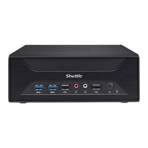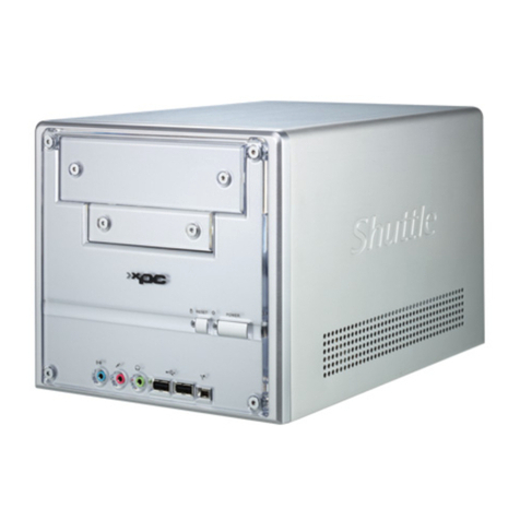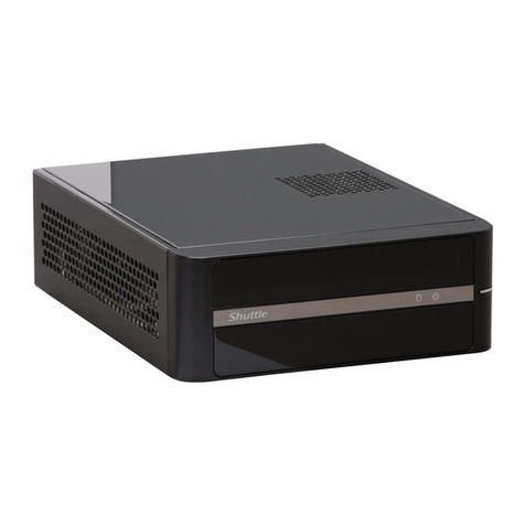
This motherboard does only support 1.2 V DDR4 SO-DIMM memory modules.
Please press the “Del” key while booting to enter BIOS. Here, please load the optimised BIOS settings.
de la BIOS.
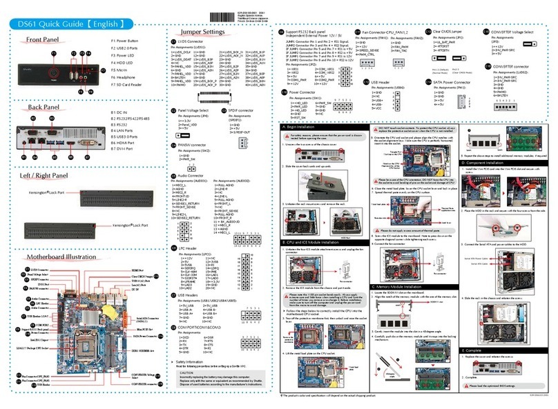
For safety reasons, please ensure that the power cord is disconnected before opening the case.
d’ouvrir le boîtier.
A.
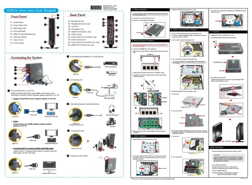
1. Unscrew the two screws of the chassis cover. Slide the cover backwards and upwards.
Lösen Sie die beiden Schrauben der Gehäuseabdeckung. Schieben Sie die Abdeckung nach hinten
und nach oben.
Desserrez et retirez les deux vis du boîtier. Glissez le couvercle vers l’arrière et le haut.
y hacia arriba.
2. Unfasten the rack mount screw and remove the rack.
Lösen Sie die Schraube des Laufwerkshalters und entfernen Sie diesen.
Desserrez les vis de montage sur rack et retirez le rack.
!
!
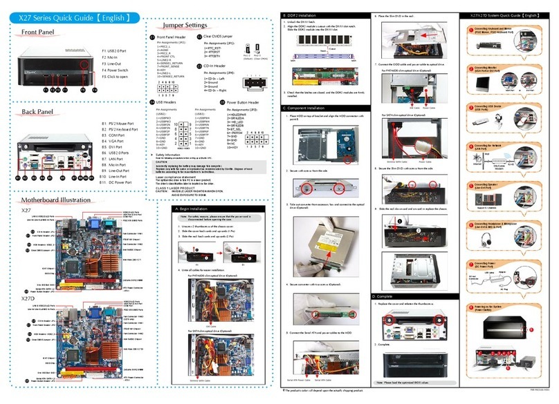
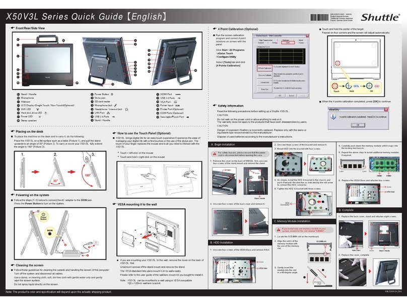
The product's colour and specifications may vary from the actually
shipping product.
Die tatsächliche Farbe des gelieferten Produktes kann von diesen
Abbildungen abweichen.
L
Product Overview
Hardware Installation
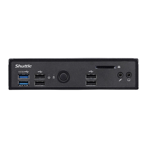
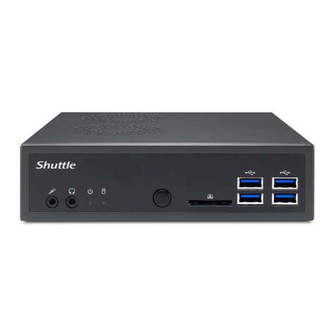
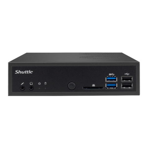
1. MIC-in
Mikrofon-Eingang
Prise micro
2. Headphones
Kopfhörer-Ausgang
Prise casque
Auriculares
3. Power LED
Betriebsanzeige-LED
Indicateur alimentation
LED de encendido
4. Hard Disk Drive LED
Festplatten-LED
Indicateur disque dur
Diodo LED del disco duro
5. Power Button
Ein-/Aus-Button
Bouton d'alimentation
6. SD Card Reader
SD Cardreader
Lector de tarjetas sd
7. USB 3.2 Gen 2 Ports
Prises USB 3.2 Gen 2
Puertos USB 3.2 Gen 2
8. COM 1 Port (RS232/RS422/RS485)
COM 1-Anschluss (RS232/RS422/RS485)
Prise COM 1 (RS232/RS422/RS485)
Puerto COM1 (RS232/RS422/RS485)
9. COM 2 Port (RS232 only)
Prise COM 2 (uniquement en RS232)
Puerto COM2 (solo RS232)
10. Power Jack (DC IN)
DC-Stromanschluss
Prise alimentation DC
11. HDMI Ports
Prises HDMI
Puertos HDMI
13. USB 3.2 Gen 1 Ports
Prises USB 3.2 Gen 1
Puertos USB 3.2 Gen 1
14. Clear CMOS & Power Button & +5V
Clear CMOS & Einschalt-Button & +5V
Reset CMOS & Bouton d’alimentation & +5V
15. Kensington®Lock Hole
Kensington®
Kensington®
®
Conector de seguridad Kensington®
®
Kensington®
12. LAN Ports
Prises LAN
Puertos LAN
1. Locate the SO-DIMM slots on the motherboard.
Lokalisieren Sie die SO-DIMM-Steckplätze
auf dem Mainboard.
carte mère.
2. Align the notch of the memory module with
the one of the relevant memory slot.
Richten Sie die Kerbe des Speichermoduls
nach der Nase im Speichersockel aus.
celle du slot DIMM.
3. Gently insert the module into the slot in a
45-degree angle.
45-Grad-Winkel in den Steckplatz.
ulo de memoria
4. Carefully push down the memory module until it
snaps into the locking mechanism.
einrastet.
Appuyez sur le module vers le bas jusqu'à
hasta que encaje.
5. Repeat the above steps to install an additional
memory module, if required.
Wiederholen Sie diese Schritte, um ggf. ein
zusätzliches Speichermodul zu installieren.
1. Locate the M.2 key slots on the motherboard.
Bitte lokalisieren Sie die M.2 Slots auf dem Mainboard.
2. Install the M.2 device into the M.2 slot and secure with the screw.
Installieren Sie die M.2-Karte in den jeweiligen M.2-Steckplatz und sichern Sie diese mit einer Schraube.
1. Place an HDD or SSD in the rack and secure with
the four screws from the sides.
Setzen Sie eine Festplatte oder SSD in die
Halterung ein und schrauben Sie sie seitlich fest.
Placez le disque dur ou SSD dans le rack et
Coloque el disco duro o la SSD en el soporte y
2. Slide the rack back into the chassis and refasten
the screws. Connect the Serial ATA cable to the
HDD or SSD.
Legen Sie die Halterung in das Gehäuse und
ziehen Sie die Schraube wieder fest an.
Verbinden Sie das SATA-Kabel mit der Festplatte
oder der SSD.
Posez le rack sur le châssis et fixez avec vis.
ou SSD.
Coloque el bastidor en el chasis y vuelva a fijarlo.
Conecte el cable de SATA con el disco duro o la
SSD.
1. Please replace and affix the case cover with two screws,then connect the power cord.
Befestigen Sie die Abdeckung wieder mit zwei Schrauben und schließen Sie das Stromkabel an.
Remettez en place le couvercle et resserrez les vis, puis branchez le câble d’alimentation.
!
2. Complete.
Fertig.
Completado.
