manuals.online logo
Brands
  1. Home
  2. •
  3. Brands
  4. •
  5. Shuttle
  6. •
  7. Desktop
  8. •
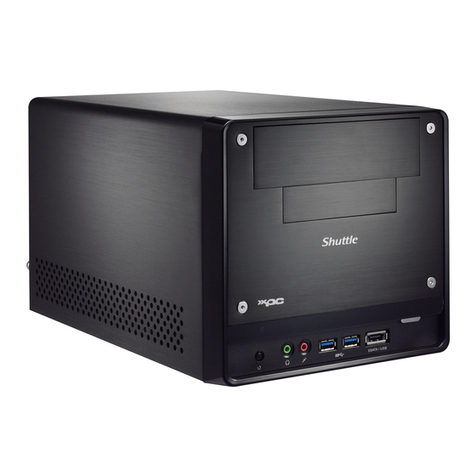
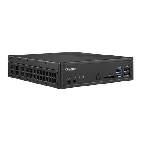
  9. Shuttle DA320 Series User manual

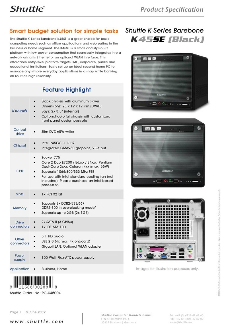
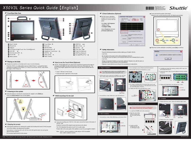
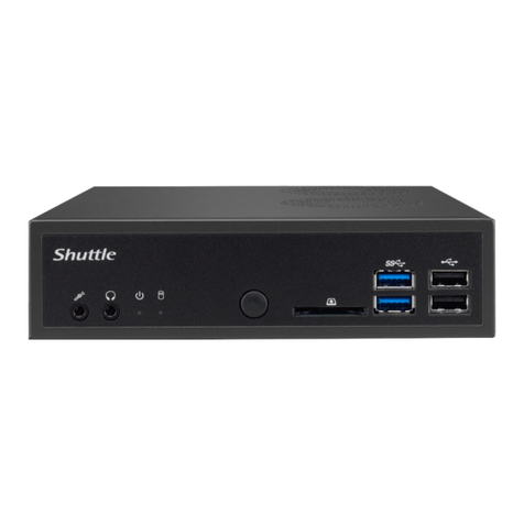
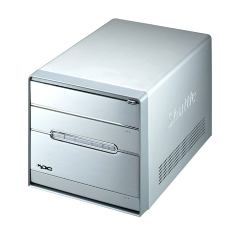
Shuttle DA320 Series User manual

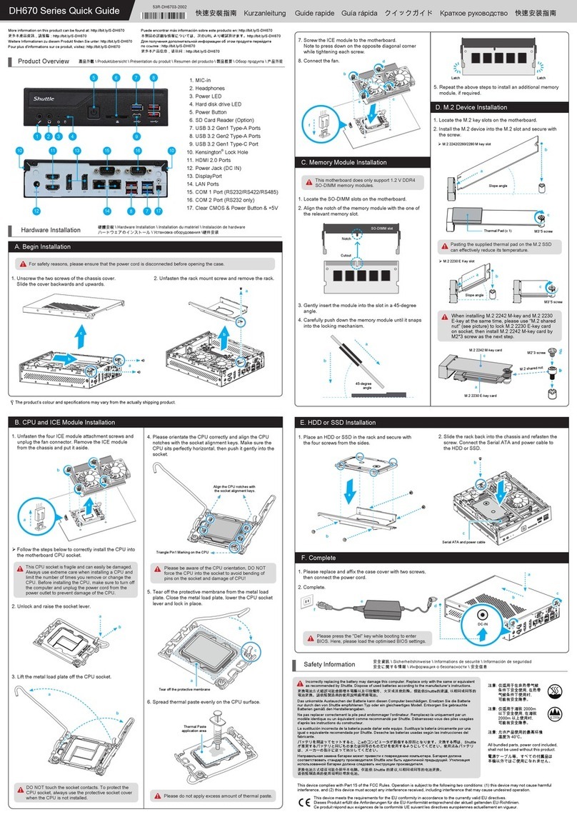
Please press the "Del" key while booting to enter BIOS.
Here, please load the optimised BIOS settings.
Incorrect placing of APU may damage APU pins.
This motherboard does only support 1.2 V DDR4
SO-DIMM memory modules.
A. Begin Installation
a
b
c
B. APU * and ICE Module Installation
!
F. HDD or SSD Installation
G. Complete
!
e
f
c
b
a
DC-IN
d
C. Memory Module Installation
Latch Latch
a
b
D. M.2 Device Installation
!
Product Overview
󳝒󱛱󶚗󶻵 \ Produktübersicht \ Présentation du produit \ Resumen del producto \ 󶻍󱛱󶤮󴮱 \ Обзор продукта \ 󱃗󱛱󶚗󴯲
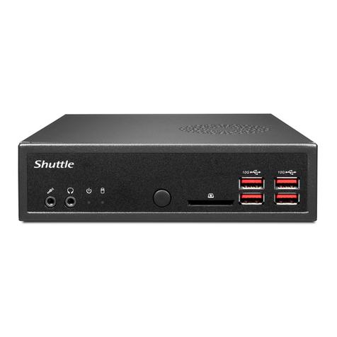
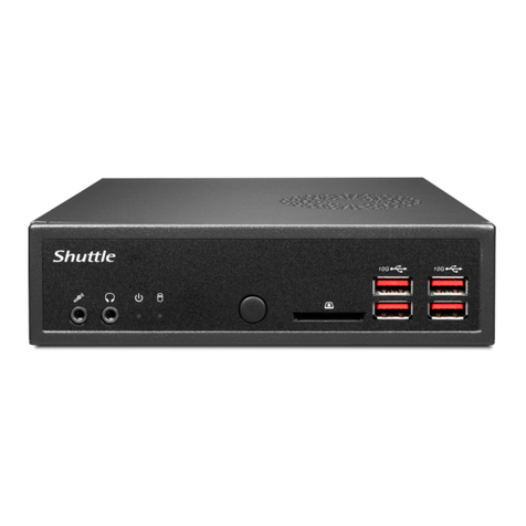
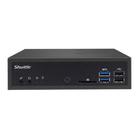
1. MIC-in
2. Headphones
3. Power LED
4. Hard disk drive LED
5. Power Button
6. SD Card Reader
7. USB 3.2 Gen1 Type-A Ports
8. Kensington®Lock Hole
9. COM 1 Port (RS232 only)
10. COM 2 Port (RS232 only)
11. DisplayPort (not supported by Athlon)
12. DisplayPort
13. Power Jack (DC IN)
14. LAN Ports
15. USB 2.0 Ports
16. HDMI 2.0 Port
17. Clear CMOS & Power Button & +5V
1. Unscrew the two screws of the chassis cover.
Slide the cover backwards and upwards.
Hardware Installation 󳪜󵴄󶛙󶻃 \ Hardware Installation \ Installation du matériel \ Instalación de hardware
󰉍󰉺󰉇󰈤󰈥󰈠󰇲󰈢󰉱󰈷󰉆󰉺󰉩 \ Установка оборудования \󳪜󱄦󶛙󴫵
2. Unfasten the rack mount screw and remove the rack.
LThe product’s colour and specifications may vary from the actually shipping product.
More information on this product can be found at: https://bit.ly/S-DA320
󲤤󱭊󲥜󳝒󱛱󴻷󶻽󶽋󴛎󴐘󰦗
Weitere Informationen zu diesem Produkt finden Sie unter: https://bit.ly/S-DA320
Pour plus d'informations sur ce produit, visitez: https://bit.ly/S-DA320
Puede encontrar más información sobre este producto en: https://bit.ly/S-DA320
󲥜󶻍󱛱󰇲󶼩󶰌󰇮󲋵󶙷󰇯󰇨󰇈󰇪󰇳󰆍󲵑󰇲󰈌󰈎󶭉󶼲󵨲󰇕󰈂󰇝󰆎

󲤤󱭊󲥜󱃗󱛱󶖆󲊟󴸧󴷯󵠞󰦗
1. Locate the SO-DIMM slots on the motherboard.
2. Align the notch of the memory module with the one of
the relevant memory slot.
3. Gently insert the module into the slot in a 45-degree
angle.
4. Carefully push down the memory module until it snaps
into the locking mechanism.
45-degree
angle
5. Repeat the above steps to install an additional memory
module, if required.
For safety reasons, please ensure that the power cord is disconnected before opening the case.
Notch
Cutout
SO-DIMM slot
1. Unfasten the four ICE module attachment screws and
unplug the fan connector. Remove the ICE module
from the chassis and put it aside.
2. Remove the protective cover and pull up the APU
socket lever to 90-degrees.
Follow the steps below to correctly install the APU into
the motherboard APU socket.
3. Align the yellow triangle (see corner of APU) with the
respective marking of Pin 1 on the APU, then gently
insert the APU into the socket and press down the
APU socket lever.
4. Spread thermal paste evenly on the APU surface.
Please do not apply excess amount of thermal paste.
!
1.
Place an HDD or SSD in the rack and secure with
the four screws from the sides.
1.
Please replace and affix the case cover with two screws,
then connect the power cord.
2.
Complete.
2.
Slide the rack back into the chassis and refasten the
screw. Connect the Serial ATA and power cable to
the HDD or SSD.
Safety Information 󶛙󶇰󴻷󶻽 \ Sicherheitshinweise \ Informations de sécurité \ Información de seguridad
󶛙󶇰󰇯󵟒󰇝󰈏󲋵󶙷 \ Информация о безопасности \ 󶛙󶇰󶖆󲊟
󲈛󷀗󶛙󶻃󲔷󱖇󰆌󰆌󰆌󰆌󰈭󰈢󰉁󰈭󰈪󰈢󰉇󰆌󰆌󲈛󷀗󶛙󴫵󲔷󱖇
DA320 Series Quick Guide
!
Incorrectly replacing the battery may damage this computer. Replace only with the same or equivalent
as recommended by Shuttle. Dispose of used batteries according to the manufacturer’s instructions.
󲤤󲘋󵤫󲺐󲟩󲄿󵕟󴳔󱘟󴌭󲤳󲘽󱬎󲥜󵤫󴎖󱄕󱗺󲅅󳢬󳐶󳋨󰆍󳊛󳊭󲑆󱎦󱄆󱖡󵣚󰆎󱋵󴌭󱇍󳢴󲄪󴶠󱄕󳤨󱘼󲑆󱘼󳵹󳢴
󵤫󲺐󲤤󲘋󰆎󴳻󱇍󳎗󴬭󵉐󱝶󳢴󱆯󳝘󴳚󲠾󴢅󳘶󲄒󵤫󲺐󰆎
Das unkorrekte Austauschen der Batterie kann diesen Computer beschädigen. Ersetzen Sie die Batterie
nur durch den von Shuttle empfohlenen Typ oder ein gleichwertiges Modell. Entsorgen Sie gebrauchte
Batterien gemäß den Herstellerangaben.
Ne pas replacer correctement la pile peut endommager l'ordinateur. Remplacez-la uniquement par un
modèle identique ou un équivalent comme recommandé par Shuttle. Débarrassez-vous des piles usagées
d’après les instructions du constructeur.


fabricante.
󰉎󰉁󰉄󰉨󰈖󵟃󵊅󰇧󰇪󰈹󰉁󰉆󰇝󰈏󰇬󰆍󰇗󰇲󰈱󰉱󰉒󰉣󰉺󰈽󰇐󲘽󱋧󰇝󰈏󱗏󱤐󰇬󰇮󰈎󰈂󰇝󰆎󱃔󲘋󰇝󰈏󵣋󰇳󰆍
󰇐󲗘󱮘󰇝󰈏󰉎󰉁󰉄󰉨󰇬󱘼󰇜󰈆󰇲󰈂󰇣󰇳󱘼󳵹󰇲󰈆󰇲󰇤󰇕󰈖󱆯󳝘󰇝󰈏󰈌󰇊󰇯󰇛󰇪󰇓󰇤󰇙󰇈󰆎󱆯󳝘󳀸󰈃󰉎󰉁󰉄󰉨
󰇳󰆍󰉟󰉺󰈩󰉺󰇲󲔷󳭪󰇯󲇃󰇧󰇪󱐖󱐶󰇛󰇪󰇓󰇤󰇙󰇈󰆎



󲤤󲖒󳝥󲺐󲟩󲄿󵝉󴸟󱘟󴌭󱅊󲖏󱥿󲥜󳝥󴍁󰆎󱃵󴌭󱇍󳢴󲄪󴷞󱄕󳤨󱘼󲑆󱘼󳵹󳢴󳝥󲺐󲤤󲖒󰆎
󴸧󱇍󳎗󱑦󵉐󱝶󳢴󱆯󳝘󴸤󲠾󱬴󳘶󲃏󳝥󲺐󰆎
!
This device complies with Part 15 of the FCC Rules. Operation is subject to the following two conditions: (1) this device may not cause harmful
interference, and (2) this device must accept any interference received, including interference that may cause undesired operation.
This device meets the requirements for the EU conformity in accordance to the currently valid EU directives.
Dieses Produkt erfüllt die Anforderungen für die EU-Konformität entsprechend der aktuell geltenden EU-Richtlinien.
Ce produit répond aux exigences de la conformité UE suivant les directives européennes actuellement en vigueur.
󲼘󶟞 󱃵󷀆󳝘󱂾󱥘󷄵󳌝󲁖󲹄󱉉
󲦑󱄦󱀻󶛙󶇰󱆯󳝘󱥘󳌝󲁖
󲹄󱉉󲦑󱄦󱀻󱆯󳝘󲠦
󱘟󶳬󲤹󶛙󶇰󵣀󲋓󰆎
󲼘󶟞 󱃵󷀆󳝘󱂾󶦵󲔄
󱄕󱀻󶛙󶇰󱆯󳝘󱥘󶦵󲔄
󱄕󱀺󱆯󳝘󲠦
󱘟󶳬󲤹󶛙󶇰󵣀󲋓󰆎
󲼘󶟞 󶖼󴷨󱃗󱛱󱆯󳝘󳢴󶣟󷆫󳗟󶚃
󳁙󶝲󱁪󰆎
All bundled parts, power cord included,
shall not be used without this product.
󵤫󳃀󰈯󰉺󰉔󰉩󳵹󰆍󰇝󰇽󰇪󰇲󱄈󱺎󱛱󰇳
󲥜󶥍󱄕󶚗󰇫󰇳󰇘󱆯󳝘󰇯󰇮󰈐󰈂󰇟󰈗󰆎
2000m
a
b
1 2 3 4 5 6
8 89 10 11
13 14 715 16 17
7
b
a
c
c
b
90-degree
angle
Triangle Pin1 Marking on the APU
c
b
a
Thermal Paste
application area
5. Screw the ICE module on to the motherboard.
Note to press down on the opposite diagonal corner
while tightening each screw.
6. Connect the fan.
a
b
cc
dd
ee
f
E. How to change the battery
1. Use a flat-blade screwdriver to gently pry the metal tab
to disengage the battery from the battery holder.
2. Install the new battery by pressing it on to the battery
holder keeping the positive side facing top.
Metal tab
a
b
2. Install the M.2 device into the M.2 slot and secure with
the screw.
1. Locate the M.2 key slots on the motherboard.
M.2 2242/2260/2280 M key slot M.2 2230 E Key slot
Slope angle
a
b
Slope angle
M.2 2230 E Key slot
M.2 2242/2260/2280 M key slot
b
a
b
a
b
c
a
Serial ATA and power cable
a
Protective cover
12
53R-DA3201-2001
* APU - Caution: AMD processor with integrated
graphics required
!
󲼘󶟞󰦗󶇲󲤹󱎗󶊢󷅗󳭪󱖑󶕔󶹫󳘶󶈡
* APU - Caution: AMD processor with integrated graphics required
* APU - Achtung: AMD Prozessor mit integrierter Grafik ist erforderlich
* APU - Attention : un processeur AMD avec graphiques intégrés est
nécessaire
* APU - Atención: se requiere un procesador AMD con gráficos
integrados
󰈮󰉧󰉓󰈡󰉁󰈭󰈷󶥍󶳬󰇐󶡖󵄹󰇙󰈐󰇪󰇈󰈏󰉕󰉫󰈹󰉁󰈳
* APU -

󲼘󶟞󰦗󶇲󲤹󱎵󶊢󲡮󳭪󷀆󷁦󶈡󶕔󱬴󳘶󶈡
This motherboard does only support 1.2 V DDR4 SO-DIMM
memory modules.
󲥜󱁫󶥍󲦯󶇣󲝟󲘤󶼅󶟿󵴄󶥇󶰕󰆎
Dieses Mainboard unterstützt nur 1,2 V DDR4 SO-DIMM Speichermodule.
Carte mère compatible uniquement avec des modules mémoire de type
1,2 V DDR4 SO-DIMM.
Esta placa base sólo soporta módulos de memoria 1,2 V DDR4 SO-DIMM.
󰇗󰇲󰉟󰈢󰉱󰉚󰉺󰉇󰇳󰇲󰉟󰉠󰉨󰉺󰉠󰈶󰉣󰉺󰉩󰇲󰈃󱸮󲈌
󰇛󰇪󰇈󰈂󰇝󰆎

󲥜󱁫󲥪󲦯󱃵󲝟󲘤󱎵󱶈󶥇󱦇󰆎
Please do not apply excess amount of thermal paste.
󶽋󱔯󱪇󲓩󷀫󱭊󳢴󶢐󶩏󶴐󶢢󱀺󰆎
Bitte verwenden Sie nicht übermäßig viel Wärmeleitpaste.
Veuillez ne pas appliquer une trop grosse quantité de pâte thermique.
No aplique una cantidad excesiva de compuesto térmico.
󱪇󰈎󰇝󰇒󰇮󰇈󰈌󰇊󰇯󲼘󶟞󰇛󰇪󱀻󰇙󰇈󰆎

󴸧󱔯󲾲󲓩󵇷󱭊󳢴󶢐󳌝󶴐󱂾󱀺󰆎
Incorrect placing of APU may damage APU pins.
󲥚󲶓󶭉󷀛󶡀󶘓󲤹󱘟󶳬󲤳󱆯󳢴󴎣󶥼󲘽󰆎
Fehlerhaftes Einsetzen der APU in den Sockel könnte die APU-Pins
beschädigen.
Une mauvaise insertion ou manipulation de l’APU pourrait endommager
ses broches.

de la APU.
󱸮󲈌󰇛󰇪󰇈󰇮󰇈󰈖󱆯󳝘󰇛󰇣󱩤󱘸󰆍󰈻󰈯󰉁󰉆󰇲󰉒󰉱󰈖󲘽󱋧󰇙󰇟󰈏󱂻󰇯
󰇮󰈎󰈂󰇝󰆎


󲥚󲶓󳪞󵈎󶡀󶘓󲤹󱘟󶳬󱅊󱆯󳢴󴍊󲷱󲖏󰆎
B. APU * and ICE Installation \ 󱶹󴬍󴢅󳘶󱢘󱗺󲞓󳏡󱸾󳷑
APU- und ICE-Installation \
Installation du processeur et du module ICE
Instalar el procesador y el módulo ICE \ APU󰇬ICE󰇲󱘆󰈎󱄈󰇕
Установка процессора и ICE \ 󱶹󴫵󱬴󳘶󱢘󱗺󲞓󳌝󱸬󳷑
1. MIC-in
󷈏󱍻󷅜󲘂󱶄
Mikrofon-Eingang
Prise micro
Micrófono
󰉜󰈢󰈭

󶃖󱍻󵫾󲘂󱶄
2. Headphones
󴉣󶥍󱶄
Kopfhörer-Ausgang
Prise casque
Auriculares
󰈢󰉢󰉙󰉱

󴉣󲥪󱶄
3. Power LED
󵤫󳃀󲔷󳭪󳏸
Betriebsanzeige-LED
Indicateur alimentation
LED de encendido
󵤫󳃀

󳝥󳃀󲔷󳭪󳊟
4. Hard disk drive LED
󳪜󳫏󲔷󳭪󳏸
Festplatten-LED
Indicateur disque dur
Diodo LED del disco duro
󰉍󰉺󰉇󰉅󰈡󰈷󰈭󰉇󰉧󰈢󰉔

󳪜󳤈󲔷󳭪󳊟
5. Power Button
󵤫󳃀󶠰󵑅
Ein-/Aus-Button
Bouton d'alimentation
Botón de encendido
󵤫󳃀󰈷󰈡󰉁󰈿

󳝥󳃀󶠰󵛞
13. Power Jack (DC IN)
󵤫󳃀󷀛󶡀󱨐
DC-Stromanschluss
Prise alimentation DC
Conexión de la fuente de alimentación (CC)
󵤫󳃀󰉛󰉺󰉆

󳝥󳃀󲘂󱶄󶬝󶦯󳝥󵇃󱎕
14. LAN Ports
󶰺󵀟󷀛󶡀󱨐
Netzwerk-Anschlüsse
Prises LAN
Puertos LAN
󰉛󰉺󰉆

󶮷󱘓
15. USB 2.0 Ports
󵉓󲗕󱨐
USB 2.0-Anschlüsse
Prises USB 2.0
Puertos USB 2.0
󰉛󰉺󰉆

󳴟󱘓
16. HDMI 2.0 Port
󷀛󶡀󱨐
HDMI 2.0-Anschluss
Prise HDMI 2.0
Puerto HDMI 2.0
󰉛󰉺󰉆

󶮷󱘓
17. Clear CMOS & Power Button & +5V
󳀵󵢔󵤫󳃀󶠰󵑅
Clear CMOS & Einschalt-Button & +5V
Reset CMOS & Bouton d’alimentation & +5V
Clear CMOS & Botón de encendido & +5V
󰈭󰉨󰈠󵤫󳃀󰈷󰈢󰉁󰈿

󳀵󵢔󳝥󳃀󶠰󵛞
6. SD Card Reader
󶾍󱖑󶥍
SD Cardreader
Lecteur de carte mémoire SD
Lector de tarjetas sd
󰈩󰉺󰉇󰉨󰉺󰈾󰉺

󱖑󳑷󵠵󴸫󲥪
7. USB 3.2 Gen1 Type-A Ports
󵉓󲗕󱨐
USB 3.2 Gen1 Typ-A-Anschlüsse
Prises USB 3.2 Gen1 Type-A
Puertos USB 3.2 Gen1 tipo A
󰉛󰉺󰉆

󳴟󱘓
8. Kensington®Lock Hole
Kensington®󲱉󶧦󷃬󳤌󷂼󱶄
Kensington®Lock Öffnung
Encoche de sécurité Kensington®
Conector de seguridad Kensington®
󰈯󰉱󰈶󰉱󰉆󰉱󰉫󰉁󰈭󳝘󰉙󰉺󰉩
®
Kensington®󲨷󶗏󷃬󳤇󵜱󱶄
9. COM 1 Port (RS232 only)
󷀛󶡀󱨐󶇣󷀼󳝘󶢢
COM 1-Anschluss (Nur für RS232)
Prise COM 1 (uniquement en RS232)
Puerto COM1 (solo RS232)
󰉛󰉺󰉆󰇲󰈃

󶮷󱘓󱃵󷀆󳝘󱂾
10. COM 2 Port (RS232 only)
󷀛󶡀󱨐󶇣󷀼󳝘󶢢
COM 2-Anschluss (Nur für RS232)
Prise COM 2 (uniquement en RS232)
Puerto COM2 (solo RS232)
󰉛󰉺󰉆󰇲󰈃

󶮷󱘓󱃵󷀆󳝘󱂾
For safety reasons, please ensure that the power cord is disconnected before opening the case.
󱨪󶢢󶛙󶇰󶲳󵏿󳰫󵞻󶥍󶥺󲡲󶽋󱍸󲔄󵢔󵤫󳃀󶱉󰆎
Achten Sie aus Sicherheitsgründen darauf, dass das Gerät vor dem Öffnen vom Stromnetz getrennt wird.
Pour des raisons de sécurité, veuillez vous assurer que le cordon d’alimentation est débranché avant d’ouvrir le boîtier.
Por razones de seguridad, no olvide desconectar el cable de alimentación antes de abrir la carcasa.
󶛙󶇰󰇲󰇣󰈅󰇯󰆍󰈯󰉺󰈷󰈖󵞻󰇕󰈏󱑽󰇯󵤫󳃀󰈱󰉺󰉇󰈖󶚗󰇛󰇪󰇈󰈏󰇗󰇬󰈖󶭉󶼲󰇛󰇪󰇓󰇤󰇙󰇈󰆎

󱨪󱂾󶛙󶇰󶲳󴢁󳰫󲄰󲥪󱬣󲠦󴸧󱍸󲔄󵢔󳝥󳃀󴃯󰆎
A.
󵞻󱯻󱶹󴬍󱘆󰈎󱄈󰇕󰇲󵞻󱯻󲄰󱯻󱶹󴫵
C. Memory Module Installation \ 󱶹󴬍󴱈󲏦󵴄󲱑󳽴
Installation der Speichermodule \ Installation de la mémoire vive
Instalar el módulo de memoria \ 󰉟󰉠󰉨󰉺󰇲󱘆󰈎󱄈󰇕
Установка модуля памяти \ 󱶹󴫵󱎵󱶈󲱑󱦇
Please press the “Del” key while booting to enter BIOS.
Here, please load the optimised BIOS settings.
󶽋󶠰󶓺󱘼󲡲󱞏󱔅󷀞󱎕󷁄󵨵󶼌󶛡
󵄹󱎕󶣟󱆣󶢈󶳬󳢴󶼌󶛡󱉬󰆎
Drücken Sie beim Starten bitte die “Entf”-Taste und laden Sie im BIOS
die “optimalen” Einstellungen.
Appuyez sur la touche “Suppr” lors du démarrage pour entrer dans le
BIOS et chargez les paramètres optimisés du BIOS.
Cuando arranque el sistema, pulse la tecla “Supr” y cargue los ajustes
“óptimos” en el programa de configuración de la BIOS.
󳝫󵦒󰇯󱎕󰈏󰇣󰈅󰆍󶾹󱔅󱁝󰇯󰈫󰉺󰈖󲓬󰇛󰇪󰇓󰇤󰇙󰇈󰆎
󶼌󶛡󳝫󵦒󰇐󶚲󰈂󰈎󰈂󰇝󰆎


󴸧󶠰󵝞󱘼󲠦󱙟󱓘󵈋󱎕󵈹󵪩󴷮󶛡
󱓐󵆭󶣟󱆣󶢈󶳬󳢴󴷮󶛡󱉬󰆎
D. M.2 Device Installation \ M.2 󴬍󴆞󱶹󴬍
Installation der M.2-Karten \ Installation des cartes M.2
Instalación de las tarjetas M.2 \
󰇡󰇲󱄆󰈱󰉱󰉛󰉺󰉋󰉱󰉆󰇲󱘆󰈎󱄈󰇕
Установка устройства M.2 \ M.2 󴫵󴆞󱶹󴫵
F. HDD or SSD Installation \ 󱶹󴬍󳪜󳫏
Installation der Festplatte oder der SSD
Installation du disque dur ou SSD \ Instalación del disco duro o la SSD
HDD/SSD󰇲󱘆󰈎󱄈󰇕 \ Установка HDD или SSD \ 󱶹󴫵󳪜󳤈
G. Complete \ 󳽴󴬍󱶼󲑀 \ Abschluss der Installation
Fin de l’installation \ Completado \ 󱶼󱂶 \ Завершение \ 󴃴󴫵󱶼󲑀
The product's colour and specifications may vary from the actually shipping product.
󱐪󴻘󶥍󳱞󷅒󴒢󶘓󴮿󲩬󷁦󶖥󱄕󶜄󵣋󱐪󴻘󶥍󳱞󳋪󶧦󰆎
Die tatsächliche Farbe des gelieferten Produktes kann von diesen Abbildungen abweichen.
Le coloris du produit livré peut varier de ces illustrations.

󶻍󱛱󰇲󴒢󶘓󰇷󰈷󰉘󰉁󰈭󰇳󰆍󱷏󵣋󰇬󳞠󰇮󰈏󱩤󱘸󰇐󰇘󰇚󰇈󰈂󰇝󰆎

󱐪󴽗󲥪󳯽󵫌󴒢󶘓󴯴󲩬󷁦󱬷󱄕󱷎󵡵󱐪󴽗󲥪󳯽󱁪󶗏󰆎
1. Locate the SO-DIMM slots on the motherboard.
󲒮󶗙󱁫󶥍󲦯󱀺󳢴󲘂󲰭󰆎
Lokalisieren Sie die SO-DIMM-Steckplätze auf dem Mainboard.
Localisez le slot mémoire SO-DIMM sur la carte mère.
Localice el zócalo SO-DIMM en la placa base.
󰇯󰉟󰉠󰉨󰉺󰈖󱘆󰈎󱄈󰇕󰈂󰇝󰆎

󲒮󶗙󱁫󲥪󲦯󱀺󳢴󲘂󲰭󰆎
2. Align the notch of the memory module with the one of the relevant
memory slot.
󶉥󶼅󶟿󵴄󶲏󱘓󱸽󶧦󲘂󲰭󱀺󳢴󱐩󲰭󱁖󶛙󲘂󶢢󲘂󲰭󱀺
󶭉󶼲󶢡󱙁󲡟󱙖󲤹󶼼󰆎
Richten Sie die Kerbe des Speichermoduls nach der Nase des
Speichersockels aus.
Alignez l'encoche du module mémoire sur celle du slot DIMM.
Alinee la muesca del módulo de memoria con la del zócalo de
memoria.
󱀻󱤣󰇲󷀔󰈎󰆍󶗖󰈎󲵐󰇕󰇯󱘸󰈓󰇟󰈂󰇝󰆎

󱸶󱎵󱶈󶲏󱘓󱸩󶗏󲘂󲰭󱀺󳢴󱐩󲰭󱸶󱎵󱶈󶛙󲘂󱂾󲘂󲰭󱀺
󲂦󳪞󴷔󶢡󱙁󲡟󱙖󲤹󴸟󰆎
3. Gently insert the module into the slot in a 45-degree angle.
󶉥󶼅󶟿󵴄󱄕󶝲󴰂󵅅󵅅󲘂󱎕󲘂󲰭󱎗󰆎
Drücken Sie das Speichermodul behutsam im 45-Grad-Winkel
in den Steckplatz.
Insérez le module mémoire délicatement dans l'encoche avec un
angle de 45 degrés.
Presione con cuidado el módulo de memoria en el zócalo con un
ángulo de 45 grados.
󰉟󰉠󰉨󰉺󰈖󰇲󴰂󶝲󰇏󰈍󲕯󰇛󱎕󰈐󰈂󰇝󰆎

󱸶󱎵󱶈󱄕󶝲󴰂󵆫󵆫󲘂󱎕󲘂󲰭󱎵󰆎
2. Unfasten the rack mount screw and remove the rack.
󷆷󵞻󲝟󲧦󱀺󳢴󱤪󶛡󶺍󶰧󱘆󱀻󲝟󲧦󰆎
Lösen Sie die Schraube des Laufwerkshalters und entfernen Sie
diesen.
Desserrez les vis de montage sur rack et retirez le rack.
Afloje el tornillo del bastidor de la unidad y retire éste.
󰉧󰉁󰈭󰉜󰈤󰉱󰉆󰉋󰈶󰈖󶚗󰇛󰆍󰉧󰉁󰈭󰈖󱘆󰈎󶚗󰇛󰈂󰇝󰆎

󶣪󲄰󲝟󲧦󱀺󳢴󱤪󶛡󶺍󱁍󱘆󱀻󲝟󲧦󰆎
1. Unfasten the four ICE module attachment screws and unplug the fan
connector. Remove the ICE module from the chassis and put it aside.
󷆷󵞻󶩏󶜐󶯆󱈻󶗖󴰂󱀺󳢴󱤪󶛡󶺍󶰧󲔄󶾹󷅜󶠘󵤫󳃀󶡀󵩝
󱘆󱀻󶢐󶩏󶥇󶰕󱍸󶲖󶢢󱀰󶢤󰆎
Lösen Sie die vier Schrauben, durch die die ICE-Kühlung fixiert wird
und ziehen Sie den Stecker vom Lüfteranschluss ab. Entfernen Sie
das ICE-Modul aus dem Gehäuse und legen es beiseite.
Desserrez les quatre vis fixées sur le système de refroidissement
ICE et retirez le connecteur du ventilateur. Retirez le module ICE
du châssis et mettez-le de côté.
Afloje los tornillos de sujeción del módulo ICE y desenchufe el conector
del ventilador. Extraiga el módulo ICE del chasis y póngalo a un lado.
󰈱󰉋󰈭󰈽󰈖󱘆󰈎󶚗󰇛󰆍󰉠󰈶󰉣󰉺󰉩󰇯󰇆󰈏󰉋󰈶󰉕󰉁󰈵󰉣󰉒󰉱
󰈖󶚗󰇛󰈂󰇝󰆎󰉠󰈶󰉣󰉺󰉩󰈖󶞔󰇑󱀺󰇖󰈏󰈌󰇊󰇯󶞔󰇑󱀺󰇖󰈏󰈌󰇊󰇯
󰇛󰇪󱘆󰈎󶚗󰇛󰈂󰇝󰆎



󶣪󲄰󳌝󱸬󶯆󱁚󶗖󴰂󱀺󳢴󱤪󶛡󶺍󱁍󲔄󶾹󵫾󶠘󳝥󳃀󶡀󱭤
󱘆󱀻󶢐󳌝󶥇󱦇󱍸󶲖󱂾󱀰󶢤󰆎
Follow the steps below to correctly install the APU into
the motherboard APU socket
󶽋󶕿󱀻󱑇󶥮󷆢󶉥󲶓󶭉󳢴󶛙󶻃󶢢󱁫󶥍󲦯󳢴󲘂󲰭󱎗
Beachten Sie genau die folgende Anleitung, um die APU korrekt in
den APU-Sockel auf dem Mainboard zu installieren.
Suivez les instructions suivantes pour réussir l'intégration de votre
processeur dans son socket.
Siga las instrucciones de abajo para instalar la APU correctamente
en el zócalo de la APU de la placa base.
󰉜󰈴󰉺󰉚󰉺󰉇󰇲󰈻󰈯󰉁󰉆󰇯󰈖󱘆󰈎󱄈󰇕󰈏󰇯󰇳󰆍
󱄕󱀻󰇲󲑻󵨶󰇯󲇃󰇧󰇪󱀻󰇙󰇈󰆎


󴸧󶕿󱀻󱑇󶥮󵳔󱸶󲶓󳪞󳢴󶛙󴫵󱂾󱁫󲥪󲦯󳢴󲘂󲰭󱎵
2. Remove the protective cover and pull up the APU socket lever to
90-degrees.
󱘆󱀻󱈍󶾊󶚡󶉥󱁫󶥍󲦯󱀺󴎣󶝳󶢤󳢴󶠩󲪯󲆰󶚗󶡂󱐪󱁖󱙁󱀺󶝲
󶠩󶾹󰆎
Entfernen Sie die Schutzfolie und bewegen Sie den Hebel des

Enlevez le film protecteur et pivotez le levier du socket de l’APU de



4. Carefully push down the memory module until it snaps into the
locking mechanism.
󶉥󶼅󶟿󵴄󲆰󱀻󶈴󶴮󱎙󱊤󱖑󲯛󶛛󶇰󶛡󶕳󰆎
Drücken Sie das Speichermodul herunter bis es einrastet.
Appuyez sur le module vers le bas jusqu'à enclenchement dans le
mécanisme d'attache.
Presione el módulo de memoria hacia abajo hasta que encaje.
󲕯󰇛󱎕󰈐󰇣󶞱󰇯󰆍󰉟󰉠󰉨󰉺󰈖󶖎󰇝󰈌󰇊󰇯󲓬󰇛󵇬󰈄󰇬󰉫󰉁󰈭󰇐󰇏󰇏
󰈎󰈂󰇝󰆎


󱸶󱎵󱶈󲆰󱀻󱖻󶴮󱁔󱇗󱖑󲯛󶛛󶇰󶛡󶕳󰆎
5. Repeat the above steps to install an additional memory module,
if required.
󶽋󵏽󴮶󱀺󶿾󶥮󷆢󶛙󶻃󱎦󷅷󳢴󶼅󶟿󵴄󶢢󲘂󲰭󱀺󰆎
Wiederholen Sie diese Schritte, um ggf. ein zusätzliches
Speichermodul zu installieren.
Répétez pour installer des modules mémoire supplémentaires si désiré.

desea.
󲇵󴮱󰇯󲈌󰇜󰇪󰆍󷀃󱓐󰇲󰉠󰈶󰉣󰉺󰉩󰈖󶱾󰈎󶿷󰇛󱘆󰈎󱄈󰇕󰈂󰇝󰆎

󴸧󵏽󱬽󱀺󶿾󶥮󵳔󶛙󴫵󱎦󱆉󳢴󱎵󱶈󱂾󲘂󲰭󱀺󰆎
1. Locate the M.2 key slots on the motherboard.
󲒮󶗙󱁫󶥍󲦯󱀺󳢴󲘂󲰭󰆎
Bitte lokalisieren Sie die M.2 Slots auf dem Mainboard.
Veuillez repérer les emplacements destinés aux cartes M.2 sur la
carte mère.
Localice la ubicación de las ranuras M.2 en la placa base.
󰉜󰈴󰉺󰉚󰉺󰉇󰇯󰇆󰈏󰈷󰉫󰉁󰉆󱘆󰈎󱄈󰇕󶕳󶲖󰈖󶭉󶼲󰇛󰈂󰇝󰆎

󲒮󶗙󱁫󲥪󲦯󱀺󳢴󲘂󲰭󰆎
2. Install the M.2 device into the M.2 slot and secure with the screw.
󶉥󶻃󶲖󲘂󱎕󲘂󲰭󱁖󷂼󱀺󱤪󶛡󶺍󶰧󰆎
Installieren Sie die M.2-Karte in den M.2-Steckplatz und sichern Sie
diese mit einer Schraube.
Installez la carte M.2 dans son emplacement et sécurisez-la avec
une vis.

󰈷󰉫󰉁󰉆󰇯󱸮󲈌󰉅󰉎󰈢󰈷󰈖󲕯󱎕󰇛󰆍
󰉋󰈶󰇫󰇛󰇧󰇏󰈎󰇬󶱌󰈅󰇪󱀻󰇙󰇈󰆎

󱸶󴫵󶲖󲘂󱎕󲘂󲰭󲂦󵜱󱀺󱤪󶛡󶺍󱁍󰆎
1. Place an HDD or SSD in the rack and secure with the four screws
from the sides.
󶉥󳪜󳫏󲑆󱤪󶟦󳪜󳫏󶢇󱎕󲝟󲧦󱁝󷂼󶱅󱎙󱊤󶺍󶰧󰆎
Setzen Sie eine Festplatte oder SSD in die Halterung ein und
schrauben Sie sie seitlich mit vier Schrauben fest.
Placez le disque dur ou SSD dans le rack et fixez-le avec les
quatre vis latérales.

firmemente por los laterales.
󰉧󰉁󰈭󰇯󰈂󰇣󰇳󰈖󶲖󰇑󰆍󱊤󵦒󰇏󰈍󲥜󰇲󰉋󰈶󰇫󱤪󶛡󰇛󰈂󰇝󰆎

󱸶󳪜󳤈󲑆󱤪󲈱󳪜󳤈󶢇󱎕󲝟󲧦󱁝󵜱󳽗󱁔󱇗󶺍󱁍󰆎
2. Slide the rack back into the chassis and refasten the screw.
Connect the Serial ATA and power cable to the HDD or SSD.
󶉥󳪜󳫏󷀛󱘼󲝟󲧦󶛙󶻃󱎕󶥍󶥺󱎗󱁖󷂼󱀺󶺍󶰧󰆎
󶛙󶻃󲗂󶱉󶴴󵤫󳃀󶱉󶢢󳪜󳫏󲘂󲰭󰆎
Legen Sie die Halterung in das Gehäuse und ziehen Sie die
Schraube wieder fest an. Verbinden Sie das Daten- und Stromkabel
mit der Festplatte oder der SSD.
Posez le rack sur le châssis et fixez le avec les vis. Connectez les
câbles série ATA et d’alimentation avec le disque dur ou SSD.
1. Please replace and affix the case cover with two screws,
then connect the power cord.
󶻃󱤎󱀺󶸇󱁖󷂼󱀺󶺍󶰧󳍦󶞱󷀛󶡀󵤫󳃀󰆎
Befestigen Sie die Abdeckung wieder mit zwei Schrauben und
schließen Sie das Stromkabel an.
Remettez en place le couvercle et resserrez les vis, puis branchez
le câble d'alimentation.

el cable de alimentación.
󰈩󰉎󰉺󰈖󱍳󰇯󲑫󰇛󰆍󰉋󰈶󰈖󱎽󰇷󱘆󰈎󱄈󰇕󰇣󰈍󰆍󵤫󳃀󰇯󶡀󳿊󰇛󰈂󰇝󰆎


󴫵󱤎󱀺󳤆󲂦󵜱󱀺󶺍󱁍󳍦󱘾󵈎󶡀󳝥󳃀󰆎
2. 󶛛󲑀󰆎
Fertig. \ Terminé.
󶛛󱂶󰇫󰇝󰆎
󶛛󲑀󰆎
Product Overview
󳝒󱛱󶚗󶻵 \ Produktübersicht \ Présentation du produit \ Resumen del producto \ 󶻍󱛱󶤮󴮱 \ Обзор продукта \ 󱃗󱛱󶚗󴯲
Hardware Installation 󳪜󵴄󶛙󶻃 \ Hardware Installation \ Installation du matériel \ Instalación de hardware
󰉍󰉺󰉇󰈤󰈥󰈠󰇲󰈢󰉱󰈷󰉆󰉺󰉩 \ Установка оборудования \󳪜󱄦󶛙󴫵
1. Unscrew the two screws of the chassis cover. Slide the cover backwards and upwards.
󷆷󵞻󱎙󵩶󶳝󲦯󶺍󶰧󶉥󶥍󶥺󲆰󶚗󶡂󱐪󱎽󱙁󱀺󲔯󶾹󰆎
Lösen Sie die beiden Schrauben der Gehäuseabdeckung. Schieben Sie die Abdeckung nach hinten und nach oben.
Desserrez et retirez les deux vis du boîtier. Glissez le couvercle vers l’arrière et le haut.
Afloje y retire primero los dos tornillos de la cubierta de la carcasa. Desplace la carcasa hacia atrás y hacia arriba.
󰈵󰉡󰉺󰈵󰈩󰉎󰉺󰇲󲥜󰇲󰉋󰈶󰈖󲓌󰇑󰈂󰇝󰆎󰈩󰉎󰉺󰈖󶞱󰈑󰇬󱀺󶢡󱙁󰇯󰈷󰉧󰈢󰉇󰇙󰇟󰈂󰇝󰆎

󶣪󲄰󱁔󵫇󶳝󲦯󶺍󱁍󱸶󲥪󱬣󲆰󶚗󶡂󱐪󱎽󱙁󱀺󲔯󶾹󰆎
󱈍󶾊󰈩󰉎󰉺󰈖󱘆󰈎󶚗󰇛󰆍󰈻󰈯󰉁󰉆󰉪󰉎󰉺󰈖󰈂󰇫󶞔󰇑󱀺󰇖󰈂󰇝󰆎


󱘆󱀻󱈍󲓔󶚡󱸶󱁫󲦯󱀺󴍊󶝳󶢤󳢴󶠩󲥶󲆰󶚗󶡂󱐪󲂦󱙁󱀺󶝲󶠩󶾹󰆎
3. Align the yellow triangle (see corner of APU) with the respective
marking of Pin 1 on the APU, then gently insert the APU into the
socket and press down the APU socket lever.
󶉥󱀺󲤹󶃳󴒢󱀹󴰂󲆒󳢴󱀰󴰂󱸽󶧦󲘂󲰭󱀺󲤹󱀹󴰂󲆒󳢴󱀰󴰂󳍦󶞱󶉥
󵅅󵅅󲘂󱎕󲘂󲰭󱁝󶈴󱀻󳢴󲘂󶝳󶠩󲪯󱁖󶛡󶕳󷂼󱮭󰆎
Richten Sie das gelbe Dreieck an der Ecke der APU mit dem Dreieck
auf dem Sockel aus und setzen Sie die APU vorsichtig in den Sockel.
Drücken Sie danach den Hebel wieder nach unten.
Alignez le triangle jaune sur le coin de l’APU avec le triangle sur le
coin du socket et insérez-y doucement l’APU. Rabaissez le levier
du socket.
Haga coincidir el triángulo amarillo en una esquina del procesador
con el de la esquina del zócalo e inserte suavemente dicho procesador
en éste. Presione hacia abajo la palanca del zócalo del procesador.
󰇲󷃼󰇲󶃴󴒢󰇈󱀹󴰂󲆒󰈖󰈻󰈯󰉁󰉆󰇲󷃼󰇲󱀹󴰂󲆒󰇯󱘸󰈓󰇟󰇮󰇐󰈍󰆍
󰈖󰈻󰈯󰉁󰉆󰇯󰇡󰇧󰇬󲕯󱎕󰇛󰈂󰇝󰆍󰈻󰈯󰉁󰉆󰉪󰉎󰉺󰈖󲓬󰇛󱀻
󰇖󰈂󰇝󰆎



󱸶󱀺󲤹󶃴󴒢󱀹󴰂󲆒󳢴󱀰󴰂󱸩󶗏󲘂󲰭󱀺󲤹󱀹󴰂󲆒󳢴󱀰󴰂󳍦󱘾󱸶
󵆫󵆫󲘂󱎕󲘂󲰭󱁝󱖻󱀻󳢴󲘂󶝳󶠩󲥶󲂦󶛡󶕳󵜱󱮭󰆎
5. Screw the ICE module on to the motherboard. Note to press down on
the opposite diagonal corner while tightening each screw.
󷂼󱀺󶩏󶜐󶯆󶙜󱈻󶗖󴰂󱀺󳢴󱤪󶛡󶺍󶰧󶉥󶢐󶩏󶥇󶰕󱤪󶛡󶢢󱁫󶥍󲦯󱀺󰆎
󶽋󶠰󶈴󶺍󶰧󱸽󴰂󶱉󶮷󱎽󶕿󶝫󷂼󱎕󱤪󶛡󰆎
Verschrauben Sie das ICE-Modul mit dem Mainboard. Drücken Sie
jeweils zwei diagonal entgegengesetzte Schrauben nach unten und
schrauben diese fest.
Vissez le module ICE à la carte mère. Lorsque vous revissez le
module, veillez à exercer une pression sur la vis opposée.
4. Spread thermal paste evenly on the APU surface.
󱘆󷀼󵏿󳢴󶢐󶩏󶴐󶙣󶗴󳢴󱪇󲓩󶢢󱀺󰆎
Tragen Sie Wärmeleitpaste gleichmäßig auf der APU-Oberfläche auf.
Appliquez la pâte thermique uniformément sur la surface du
processeur.
Extienda la pasta térmica regularmente sobre la superficie del APU.
󰇲󶺣󵦒󰇯󶩏󶕰󶜐󰈮󰉨󰈷󰈖󱪇󲀳󰇛󰈂󰇝󰆎

󱘆󷀆󵏿󳢴󶢐󳌝󶴐󶙣󱔰󳢴󲾲󲓩󱂾󱀺󰆎
Atornille el módulo ICE a la placa base. Presione la esquina diagonal
opuesta hacia abajo cuando apriete cada uno de los tornillos.
󰉜󰈴󰉺󰉚󰉺󰉇󰇼󰉠󰈶󰉣󰉺󰉩󰇯󰇆󰈏󰉋󰈶󰉕󰉁󰈵󰉣󰉒󰉱󰈖󶱌󰈅󰈂
󰇝󰆎󰇡󰈐󰇢󰈐󲓬󰇛󵇬󰈄󰈌󰇊󰇯󰇛󰇮󰇐󰈍󶱌󰈅󰈏󰈌󰇊󰇯󰇛󰈂󰇝󰆎



󵜱󱀺󳌝󱸬󶯆󶙜󱁚󶗖󴰂󱀺󳢴󱤪󶛡󶺍󱁍󱸶󶢐󳌝󶥇󱦇󱤪󶛡󱂾󱁫󲥪󲦯󱀺󰆎
󴸧󶠰󱖻󶺍󱁍󱸩󴰂󴃯󶮷󱎽󶕿󶝫󵜱󱎕󱤪󶛡󰆎
6. Connect the fan.
󷀛󶡀󷅜󶠘󳢴󵤫󳃀󶡀󵩝󰆎
Schließen Sie den Lüfterstecker an das Mainboard an.
Branchez le connecteur de ventilateur.
Enchufe el conector del ventilador.
󰈱󰉋󰈭󰈽󰇼󰈱󰉋󰈭󰈽󰈖󶡀󳿊󰇛󰈂󰇝󰆎

󵈎󶡀󵫾󶠘󳢴󳝥󳃀󶡀󱭤󰆎
1. Use a flat-blade screwdriver to gently pry the metal tab to disengage
the battery from the battery holder.
󱆯󳝘󱀰󶛌󶺍󶰧󱐰󵅅󵅅󲛜󱔅󵐁󶜙󱖑󶴷󶉥󵤫󲺐󱘆󱐪󰆎
Verwenden Sie einen Schlitzschraubendreher, um vorsichtig gegen
die Metallhalterung zu drücken und die Batterie herauszulösen.
Utilisez un tournevis plat pour pousser doucement contre le support
métallique et pour ainsi libérer la batterie.
Utilice un destornillador plano para presionar un poco el soporte de

󰉜󰈢󰉈󰈷󰉇󰉧󰈢󰉎󰉺󰈖󱆯󳝘󰇛󰇪󵐁󱺎󰈽󰉔󰈖󰇗󰇜󰈏󰈌󰇊󰇯󰇛󰇪󰆍
󰉎󰉁󰉄󰉨󰉺󰉙󰉩󰈾󰉺󰇏󰈍󰉎󰉁󰉄󰉨󰉺󰈖󱘆󰈎󶚗󰇛󰈂󰇝󰆎


󱆯󳝘󱀰󶛌󶺍󱁍󱐰󵆫󵆫󲛜󱓘󵐁󱺎󱖑󶴷󱸶󳝥󲺐󱘆󱐪󰆎
2. Install the new battery by pressing it on to the battery holder keeping
the positive pole facing up.
󶛙󶻃󶢟󵤫󲺐󶉥󱎦󶠰󱎕󵤫󲺐󶝳󱁝󱆯󲶓󶌱󲥍󱀺󰆎
Installieren Sie die neue Batterie, indem Sie sie vorsichtig in ihre
Halterung drücken und dabei darauf achten, dass der Pluspol nach
oben zeigt.
Installez la nouvelle batterie en la poussant doucement dans son
support, en vous assurant que le pôle positif est orienté vers le haut.

que el polo positivo apunte arriba.
󰉎󰉁󰉄󰉨󰉺󰉙󰉩󰈾󰉺󰇯󲶓󰇛󰇈󶕳󶲖󰇫󶢟󰇛󰇈󰉎󰉁󰉄󰉨󰉺󰈖󲓬󰇛󱎕󰈐󰈂󰇝󰆎


󶛙󴫵󶢟󳝥󲺐󱸶󱎦󶠰󱎕󳝥󲺐󲰭󱁝󱆯󲶓󲦱󲥍󱀺󰆎
E.
How to change the battery \ 󱮲󱆅󲤤󲘋󵤫󲺐 \ Tauschen der Batterie
Comment changer la batterie \ Cambio de la batería
󰉎󰉁󰉄󰉨󰉺󰇲󱃔󲘋󲟩󲼅 \ Как сменить аккумулятор \ 󱮲󱆅󲤤󲖒󳝥󲺐
Coloque el bastidor en el chasis y vuelva a fijarlo. Conecte el cable de
datos y el de alimentación con el disco duro o la SSD.
󰈵󰉡󰉺󰈵󰇯󰉧󰉁󰈭󰈖󰈹󰉁󰉆󰇛󰆍󰉧󰉁󰈭󰈖󱎽󰇷󰉋󰈶󰇫󱤪󶛡
󰇛󰈂󰇝󰆎󰈵󰉨󰈠󰉩󰇬󵤫󳃀󰈯󰉺󰉔󰉩󰈖󰇯󶡀󳿊󰇛󰈂󰇝󰆎


󱸶󳪜󳤈󵈎󱘼󲝟󲧦󶛙󴫵󱎕󲥪󱬣󱎵󲂦󵜱󱀺󱤪󶛡󶺍󱁍󰆎
󶛙󴫵󲗂󴃯󶕎󳝥󳃀󴃯󱂾󳪜󳤈󲘂󲰭󰆎
11. DisplayPort (not supported by Athlon)
󷀛󶡀󱨐󱀽󲝟󲘤󲶔)
DisplayPort (funktioniert nicht bei Athlon-CPUs)
DisplayPort
(ne fonctionne pas avec les processeurs Athlon).
DisplayPort (no funciona con las CPU de Athlon)
󰉅󰈡󰈷󰉕󰉪󰈢󰉛󰉺󰉆󰦅󰇳󷄵󰈳󰉛󰉺󰉆󰦆

󶮷󱘓󱀽󲝟󲘤󲶔
12. DisplayPort
󷀛󶡀󱨐
DisplayPort
Prise DisplayPort
DisplayPort
󰉅󰈡󰈷󰉕󰉪󰈢󰉛󰉺󰉆
DisplayPort
󶮷󱘓
!
!
!
!
!
L
!
Motherboard Illustration 󱁫󶥍󲦯󶽁󲠾 \ Mainboard-Abbildung \ Illustration de la carte mère \ Ilustración de la placa base
󰉟󰈢󰉱󰉚󰉺󰉇󱤣 \ Материнская плата. Иллюстрация \ 󱁫󲥪󲦯󴸤󲠾
01. USB 3.2 Gen1 Type-A Ports
󷀛󶡀󱨐
USB 3.2 Gen1 Typ-A Anschlüsse
Prises USB 3.2 Gen1 Type-A
Puertos USB 3.2 Gen1 tipo A
󰉛󰉺󰉆

USB 3.2 Gen1 Type-A 󶮷󱘓
02. 󶾍󱖑󶥍
SD Cardreader
Lecteur de carte mémoire SD
Lector de tarjetas sd
󰈩󰉺󰉇󰉨󰉺󰈾󰉺

󱖑󳑷󵠵󴸫󲥪
03. 󵤫󳃀󶠰󵑅
Ein-/Aus-Button \ Bouton d'alimentation
󵤫󳃀󰈷󰈡󰉁󰈿
󳝥󳃀󶠰󵛞
04. 󵤫󲺐󲃗
CMOS Batterie-Halterung
Support de batterie CMOS
Soporte de pila de CMOS
󰉎󰉁󰉄󰉨󰉺󰉙󰉩󰈾󰉺

󳝥󲺐󲰭
05. Hard disk drive LED
󳪜󳫏󲔷󳭪󳏸
Indicateur disque dur
Diodo LED del disco duro
󰉍󰉺󰉇󰉅󰈡󰈷󰈭󰉇󰉧󰈢󰉔

󳪜󳤈󲔷󳭪󳊟
06. 󵤫󳃀󲔷󳭪󳏸
Betriebsanzeige-LED
Indicateur alimentation
󵤫󳃀

󳝥󳃀󲔷󳭪󳊟
07. Headphones
󴉣󶥍󱶄
Kopfhörer-Ausgang
Prise casque
Auriculares
󰈢󰉢󰉙󰉱

󴉣󲥪󱶄
08. MIC-in
󷈏󱍻󷅜󲘂󱶄
Mikrofon-Eingang
Prise micro
Micrófono
󰉜󰈢󰈭

󶃖󱍻󵫾󲘂󱶄
09. DDR4 SO-DIMM slots
󲘂󲰭
DDR4 SO-DIMM Steckplätze
Slot mémoire SO-DIMM DDR4
zócalo de DDR4 SO-DIMM
󰈷󰉫󰉁󰉆

󲘂󲰭
10. Processor socket AM4
󶹫󳘶󶈡󲘂󶝳
Sockel für AM4
Socket Processeur AM4
Zócalo AM4 de APU
󰉕󰉫󰈹󰉁󰈳󰈻󰈯󰉁󰉆

󱬴󳘶󶈡󲘂󶝳
11. M.2 2230 E key slot
󲘂󲰭
M.2-2230 (E) Steckplatz
Emplacement M.2 2230 E
Ranura M.2 2230 E
󰈫󰉺󰈷󰉫󰉁󰉆

󲘂󲰭
12. SATA connector
󲗂󶱉󲘂󶝳
SATA-Anschluss
Connecteur SATA
Base de conexiones SATA
󰈱󰉋󰈭󰈽

󶡀󱘓
13. A320 Chipset
󲢦󳑷󶰕
A320 Chipsatz
A320 Chipset
A320 Conjunto de chips
󰈿󰉁󰉕󰈹󰉁󰉆

󶵥󳑷󴃴
14. M.2 2242/2260/2280 M key slot
󲘂󲰭
M.2-2242/2260/2280 (M) Steckplatz
Emplacement M.2 2242/2260/2280 M
Ranura M.2 2242/2260/2280 M
󰈫󰉺󰈷󰉫󰉁󰉆

󲘂󲰭
15. Power Jack (DC IN)
󵤫󳃀󷀛󶡀󱨐
DC-Stromanschluss
Prise alimentation DC
Conexión de la fuente de alimentación (CC)

󵤫󳃀󰉛󰉺󰉆
󳝥󳃀󲘂󱶄󶬝󶦯󳝥󵇃󱎕
17. USB 2.0 Ports
󷀛󶡀󱨐
USB 2.0 Anschlüsse
Prises USB 2.0
Puertos USB 2.0
󰉛󰉺󰉆

󶮷󱘓
18. DisplayPort (not supported by Athlon)
󵉓󲗕󱨐󱀽󲝟󲘤󲶔
DisplayPort (funktioniert nicht bei Athlon-CPUs)
DisplayPort
(ne fonctionne pas avec les processeurs Athlon).
DisplayPort (no funciona con las CPU de Athlon)
󰉅󰈡󰈷󰉕󰉪󰈢󰉛󰉺󰉆󰦅󰇳󵦎󰈳󰉛󰉺󰉆󰦆

󳴟󱘓󱀽󲝟󲘤󲶔
19. DisplayPort
󷀛󶡀󱨐
DisplayPort
Prise DisplayPort
DisplayPort
󰉅󰈡󰈷󰉕󰉪󰈢󰉛󰉺󰉆
DisplayPort
󶮷󱘓
Jumper 󶼌󶛡 \ Jumper-Einstellungen \ Réglages cavaliers \ Configuración de los puentes
󰈶󰉡󰉱󰉏󰉺󶼌󶛡 \ Настройки переключателя \ Jumper 󴷮󶛡
Jumper Settings
󱤎󵤫󴐚󱔅󵞻󱞏󵤫󳃀
Automatisches Einschalten bei Spannungsversorgung
Démarrage automatique à la mise sous tension
Encendido automático con suministro de corriente
󴐚󱔅󵤫󳃀󰈨󰉱󱤎󳝥󴐚󱓘󲄰󱙟󳝥󳃀

J5
JP3
Pin Signal Name
1 U30B_pin10
2 GND
1 2 3 4
󷅜󶠘󷀛󶡀󱨐
Lüfteranschluss \ Connecteur ventilateur
󰈱󰉋󰈭󰈽
󵫾󶠘󲘂󶝳
J1

Pin Signal Name
1 GND
2 +12V
3 SPEED_SENSE
4 PWM_CTRL
4
3
2
1
󲘂󶝳
USB-Anschluss \ Connecteur USB
󰈱󰉋󰈭󰈽󰉺
󶡀󱭤
J7
USB6
Pin Signal Name
1 GND
2 USB +
3 USB -
4 5V_USB
2 4 6 8 10
1 3 5 7 9
Debug header
󲘂󶝳
Debug-Anschluss
Connecteur Debug
Conexión Debug
󰉅󰉎󰉁󰈮󰉖󰉁󰈾

󶡀󱭤
J2 DBG1
Pin Signal Name
1 LPC_24M
2 LAD1
3 SIORST-
4 LAD0
5
6 +3.3V
7 LAD3
8 GND
9 LAD2
10 NULL
J9
Clear CMOS & power button & +5V
󳀵󵢔󵤫󳃀󶠰󵑅
Clear CMOS & Einschalt-Button & +5V
Reset CMOS & Bouton d’alimentation & +5V
Clear CMOS & Botón de encendido & +5V
󰈭󰉨󰈠󵤫󳃀󰈷󰈢󰉁󰈿

󳀵󵢔󳝥󳃀󶠰󵛞
2 4
1 3
Open
(enabled)
1
2
Short
(disabled)
1
2
SW1
Pin Signal Name
1 RTCRST-
2 +5V
3GND
4 PWRSW-
01 02 03 05 0604
08
07
J1
J2
09 10
13
J3
J4
J5 J6
J7
12
1615 01 17 20
J9
J8
14
11
16. LAN Ports
󶰺󵀟󷀛󶡀󱨐
Netzwerk-Anschlüsse
Prises LAN
Puertos LAN
󰉛󰉺󰉆

󶮷󱘓
J3 󲘂󶝳
COM-Ausgang \ Port COM
󰉖󰉁󰈾
󶡀󱭤
COM2
Pin Signal Name
1 DCD
2 RX
3 TX
4 DTR
5 GND
6 DSR
7 RTS
8 CTS
9 RI(NA)
10 NULL
1
3
5
7
9
2
4
6
8
10
J4 󲘂󶝳
COM-Ausgang \ Port COM
󰉖󰉁󰈾
󶡀󱭤
1
3
5
7
9
2
4
6
8
10
COM1
Pin Signal Name
1 DCD
2 RX
3 TX
4 DTR
5 GND
6 DSR
7 RTS
8 CTS
9 RI
10 NULL
J6 󲘂󶝳
VGA-Anschluss \ Connecteur VGA
󰈱󰉋󰈭󰈽󰉺
󶡀󱭤
CN3
Pin Signal Name Pin Signal Name
1 GND 2 GND
3 SDVO_CLK 4 GND
5 SDVO_DATA 6 GND
7 GND 8 GND
9 CRT_VSYNC 10 GND
11 CRT_HSYNC 12 GND
13 GND 14 GND
15 BOUT-O 16 VGA_PWR
17 GOUT-O 18 VGA_PWR
19 ROUT-O 20 VGA_PWR
20
2
19
1
D-Sub & DP video switch
D-Sub & DP video jumper
D-Sub & DP Video-Umschalter
Choix de sortie video D-Sub & DisplayPort
Interruptor de video D-Sub y DP.
󶘓󰇷󰉅󰈡󰈷󰉕󰉪󰈢󰉛󰉺󰉆󱐪󱓋󰈷󰈢󰉁󰈿

D-Sub & DP video jumper
J8
JP11
Pin Signal Name
1-2 OPEN D-SUB
1-2 Short DP
Open
(D-Sub)
1
2
Short
(DP video)
1
2
18 19
20. HDMI 2.0 Port
󵉓󲗕󱨐
HDMI 2.0-Anschluss
Prise HDMI 2.0
Puerto HDMI 2.0
󰉛󰉺󰉆

󳴟󱘓

Other Shuttle Desktop manuals

Shuttle DH110 Series User manual

Shuttle

Shuttle DH110 Series User manual

Shuttle SZ170R8 User manual

Shuttle

Shuttle SZ170R8 User manual

Shuttle XH170V Series User manual

Shuttle

Shuttle XH170V Series User manual

Shuttle XPC User manual

Shuttle

Shuttle XPC User manual

Shuttle XPC SD30 User manual

Shuttle

Shuttle XPC SD30 User manual

Shuttle XPC SD31P User manual

Shuttle

Shuttle XPC SD31P User manual

Shuttle XC60J User manual

Shuttle

Shuttle XC60J User manual

Shuttle XPC SD36G5M User manual

Shuttle

Shuttle XPC SD36G5M User manual

Shuttle DH02U User manual

Shuttle

Shuttle DH02U User manual

Shuttle DH410S Series User manual

Shuttle

Shuttle DH410S Series User manual

Shuttle SZ77R5 User manual

Shuttle

Shuttle SZ77R5 User manual

Shuttle P92U User manual

Shuttle

Shuttle P92U User manual

Shuttle SH87R6 User manual

Shuttle

Shuttle SH87R6 User manual

Shuttle XPC Barebone SH67H3 Owner's manual

Shuttle

Shuttle XPC Barebone SH67H3 Owner's manual

Shuttle XPC User manual

Shuttle

Shuttle XPC User manual

Shuttle SH310R4 User manual

Shuttle

Shuttle SH310R4 User manual

Shuttle Barebone XS 35V2 User manual

Shuttle

Shuttle Barebone XS 35V2 User manual

Shuttle DH670 User manual

Shuttle

Shuttle DH670 User manual

Shuttle XS35V4 Series User manual

Shuttle

Shuttle XS35V4 Series User manual

Shuttle DS10U Series User manual

Shuttle

Shuttle DS10U Series User manual

Shuttle Mini-PC User manual

Shuttle

Shuttle Mini-PC User manual

Shuttle XH410G User manual

Shuttle

Shuttle XH410G User manual

Shuttle Prima XPC Barebone SX48P2 Deluxe User manual

Shuttle

Shuttle Prima XPC Barebone SX48P2 Deluxe User manual

Shuttle Prima XPC Barebone SX48P2 Deluxe Owner's manual

Shuttle

Shuttle Prima XPC Barebone SX48P2 Deluxe Owner's manual

Popular Desktop manuals by other brands

Zotac ZBOX HD-ID41 PLUS user guide

Zotac

Zotac ZBOX HD-ID41 PLUS user guide

HP Compaq dx6120 ST Hardware reference guide

HP

HP Compaq dx6120 ST Hardware reference guide

Lenovo ThinkCentre A58 manual

Lenovo

Lenovo ThinkCentre A58 manual

HP Compaq Presario supplementary guide

HP

HP Compaq Presario supplementary guide

Lenovo 17024EU Brochure & specs

Lenovo

Lenovo 17024EU Brochure & specs

HP Workstation xw8000 Compatibility chart

HP

HP Workstation xw8000 Compatibility chart

HP Z210 Series Quick reference card

HP

HP Z210 Series Quick reference card

Lenovo ThinkStation E31 Configuration guidelines

Lenovo

Lenovo ThinkStation E31 Configuration guidelines

Lenovo ThinkCentre A70z ALL-IN-ONE Felhasználói kézikönyv

Lenovo

Lenovo ThinkCentre A70z ALL-IN-ONE Felhasználói kézikönyv

Intergraph TDZ 2000 GL1 System setup

Intergraph

Intergraph TDZ 2000 GL1 System setup

Asus M32BFBF user manual

Asus

Asus M32BFBF user manual

Lenovo ThinkCentre M71z Käyttöopas

Lenovo

Lenovo ThinkCentre M71z Käyttöopas

Alienware AURORA D0IM Service manual

Alienware

Alienware AURORA D0IM Service manual

Lenovo ThinkCentre A51 Referencia Rápida

Lenovo

Lenovo ThinkCentre A51 Referencia Rápida

Barco Vista 4000 series Brochure & specs

Barco

Barco Vista 4000 series Brochure & specs

Zenith H-100 Service manual

Zenith

Zenith H-100 Service manual

IBM 8131 user guide

IBM

IBM 8131 user guide

HP Z1 G2 Maintenance and service guide

HP

HP Z1 G2 Maintenance and service guide

manuals.online logo
manuals.online logoBrands
  • About & Mission
  • Contact us
  • Privacy Policy
  • Terms and Conditions

Copyright 2025 Manuals.Online. All Rights Reserved.