Siargo FS35001 User manual
FS35001 User Manual
MEMS Mass flow sensors for manifold installation
©2022 Siargo Ltd.
VA.0.01

2
www.Siargo.com FS35001 User Manual
MEMS Mass Flow Sensors
With proprietary thermal-D® sensing for manifold configuration
FS35001 Series
User Manual
Document No. 08-2022-FSTD4 EN
Issue date: 2022.08
Revision: VA.0.01
Siargo Ltd.
3100 De La Cruz Boulevard, Suite 210
Santa Clara, California 95054
USA
Tel: +1(408)969.0368
© Copyright 2022 and Liability Disclaimer
Siargo Ltd. and its subsidiaries reserve the right to change the specifications and/or descriptions
without prior notice. Siargo and its subsidiaries shall not assume any inaccuracy or errors in this
manual. For further information and updates, please visit www.Siargo.com.
3
www.Siargo.com FS35001 User Manual
Attention !
Use with caution !
•Please carefully read this manual prior to operating this product.
•Do not open or modify any hardware which may lead to irrecoverable
damage.
•Do not use this product if you suspect any malfunctions or defection.
•Do not use this product for corrosive media or in a strong vibration
environment.
•Use this product according to the specified parameters.
•Only the trained or qualified personnel shall be allowed to perform
product services.
•Be cautious for electrical safety, and even it operates at a low voltage,
any electrical shock might lead to some unexpected damages.
•The gas to be measured should be clean and free of particles, as
even light particles may be accumulated inside the tiny pressure port
that may result in inaccuracy in metrology, clogging, or other
irrecoverable damage.
•Do not apply for any unknown or non-specified gases that may
damage the product.

4
www.Siargo.com FS35001 User Manual
Table of Contents
1. Overview.................................................................................................. 5
2. Receipt / unpack of the products ................................................................ 6
3. Knowing the products ............................................................................... 7
3.1 Product description ...................................................................................................7
3.2 Power and data pinout description .............................................................................7
3.3 Mechanical dimensions..............................................................................................8
4. Installation............................................................................................... 9
5. Basic operation........................................................................................10
5.1 I2C interface connection diagram........................................Error! Bookmark not defined.
5.2 I2C interface command description .....................................Error! Bookmark not defined.
5.3 I2C interface read/write sequences......................................Error! Bookmark not defined.
6. Product selection.....................................................................................10
7. Product performance ...............................................................................16
7.1 Technical specifications ........................................................................................... 17
7.2 Typical (analog) output............................................................................................18
7.3 Pressure loss...........................................................................................................18
8. Technical notes for the product performance.............................................19
8.1 Measurement principles...........................................................................................19
8.2 Precautions for the best performance of the product .................................................19
8.2.1 Contamination and sterilization ...................................................................................19
8.2.2 Altitude changes.........................................................................................................19
8.2.3 Excessive humidity or condensation .............................................................................20
8.2.4 Metrology verification .................................................................................................20
9. Warranty and Liability..............................................................................21
10. Service contact and information ...............................................................23
Appendix I: Sensor evaluation kit ...................................................................24
Appendix II: Document history.......................................................................25

5
www.Siargo.com FS35001 User Manual
1. Overview
This manual provides essential information for the operation of the FS35001 series of gas mass flow
sensors for general-purpose gas flow monitor and control applications with the full-scale mass flow
rate from 0.2 to 20 SLPM, and both analog and digital outputs. The product performance,
maintenance, and troubleshooting as well as the information for product order, technical support,
and repair are also included.
FS35001 product provides the manifold configuration for the mechanical connections. Optionally it
can also be offered with a manifold body with the 4mm one-touch flexible piping. It can be applied
to medical equipment and instrumentation applications. The series covers a wide dynamic flow
range with a working pressure rating of up to 1.0 MPa (10 bar or 150 PSI), and a compensated
temperature ranging from -5 to 50°C.
The sensing elements are manufactured with Siargo’s proprietary MEMS (micro-electro-mechanical
systems) thermal mass flow sensing technologies (Thermal-D®) that measures the calorimetry and
diffusivity of the flow medium. The sensor surface is passivated with silicon nitride ceramic materials
together with a water/oil proof nano-coating for performance and reliability. Compared to the
conventional calorimetric flow sensing technology, this unique sensing approach offers better
linearity, removes gas sensitivity for gases with similar thermal diffusivities, and improves
temperature performance. It can also auto recognize pre-programmed gases with significant
differences in thermal diffusivity. It is the first of the kind in the industry that senses the mass flow
with multiple gases without a manual gas conversion factor. As such, it ensures high precision for gas
measurements with air calibration.
Thermal-D
®is a trademark of Siargo’s thermal sensing technology.
6
www.Siargo.com FS35001 User Manual
2. Receipt / unpack of the products
Upon receipt of the products, please check the packing box before the dismantlement of the packing
materials. Ensure no damages during shipping. If any abnormality is observed, please contact and
notify the carrier who shipped the product and inform the distributors or sales representatives if the
order is not placed directly with the manufacturer; otherwise, the manufacturer should be informed.
For any further actions, please refer to the return and repair section in this manual.
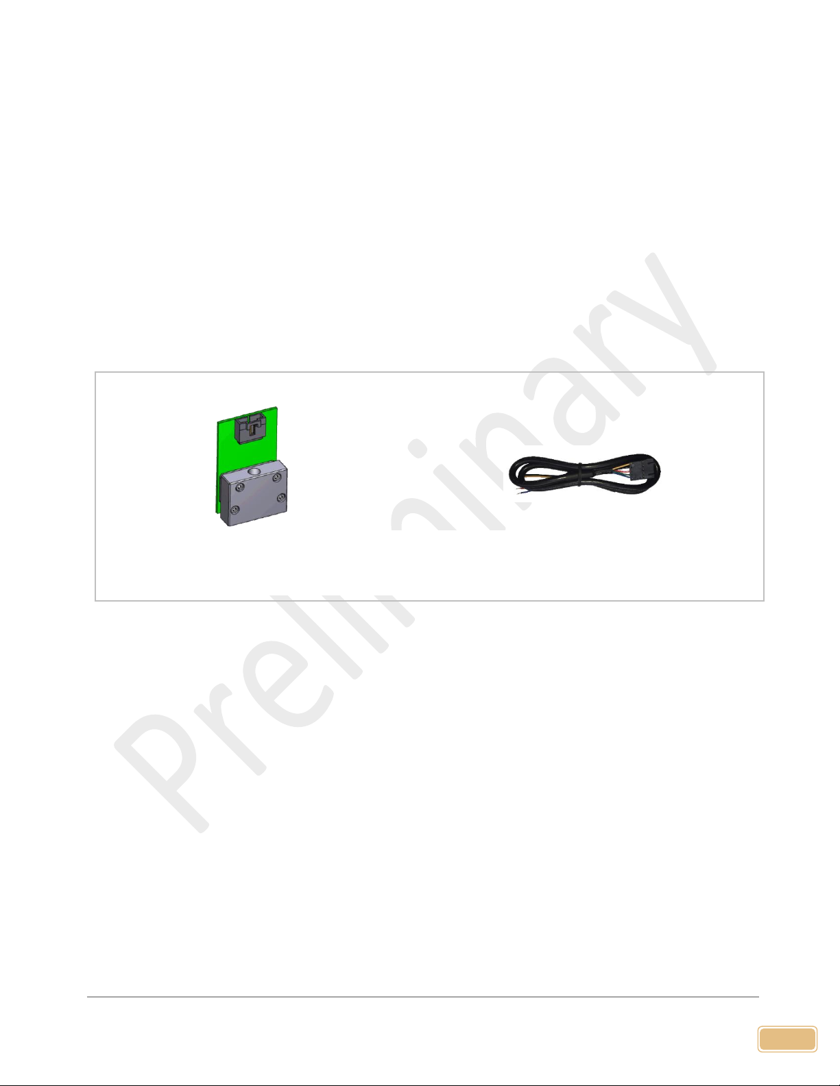
If the packing box is intact, proceed to open the packing box, and you shall find the product (either
the sensor formality per the actual order), together with the power and data cable if the order is
included as shown below.
Please check immediately for the integrity of the product and the power and data cable; if any
abnormality is identified, please notify the distributor/sales representative or manufacturer as soon
as you can. If any defects are confirmed, an exchange shall be arranged immediately via the original
sales channel. This user manual shall also be included in the packing box or via an online link for an
electronic version which should be sent by your sales agent. In most cases, this manual shall be made
available to the customer before the actual order.
FS35001 Power and data cable (optional)
Figure 2.1: FS35001 flow sensor and accessories
7
www.Siargo.com FS35001 User Manual
3. Knowing the products
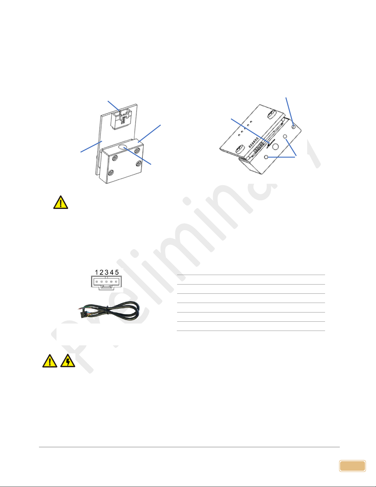
3.1 Product description
Figure 3.1: FS35001 parts description
3.2 Power and data pinout description
Table 3.1: FS35001 pin/wire assignments.
DO NOT connect or disconnect the sensor cable when power is on!! It will damage the
electronic chipsets inside the sensor module! The standard cable has an AMPMODU
MTE (5 positions) compatible connector with a length of 0.5 meters.
Note: 1. Power supply: The FS35001 requires a power supply of 8 ~ 24 Vdc. No particular requirements for
the external power supply, but standard industrial power cautions should be applied.
2. The analog outputs 0.5 ~ 4.5 Vdc are corresponding to the specified full-scale flow range at the
time of order. If the analog option is not selected, this pin output could be NULL.
Wire
Color
Definition
1
Blue
RS485 B(+) / SDA(I2C)
2
Green
Analog output, 0.5 ~ 4.5 Vdc
3
Red
Power supply, 8 ~ 24 Vdc
4
Black
Ground
5
Yellow
RS485 A(-) / SCL(I2C)
Control
electronics
Data/power socket
Flow block
Installation
mounting port.
Note: The manifold base port size should not be smaller than those of the flow ports on the
product.
Manifold flow
ports
Figure 3.2: FS35001 pinout
2.54mm centers; 0.635mm square
Flow direction
Dowel pin port
8
www.Siargo.com FS35001 User Manual
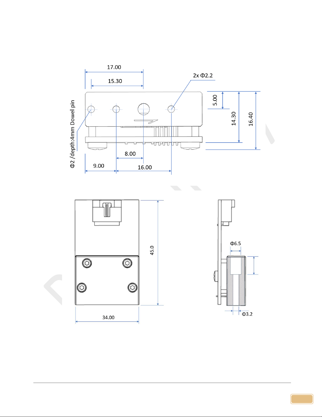
3.3 Mechanical dimensions
Figure 3.3.1. FS35001 manifold mechanical dimensions.

9
www.Siargo.com FS35001 User Manual
4. Installation
Do not open or alter any part of the product, which would lead to malfunction and irrecoverable
damage.
For the installation, make sure the leakage proof of the connections and all electrical precautions are
applied. Please make sure the electrical cable is properly engaged. It should be noted that the sensor
is designed for medium to low pressure per the applications, therefore, the system design would be
important for the flow stability and related flow noises.
In order to prevent over-forced installation, The mounding torque applied should be within 0.35±0.03
N·m. Sealing O-ring is recommended to be the ones that comply with ISO 3601/1; the mounting
screw is specified for M3x20mm by ISO 14583; the dowel pin should be Φ2m6x6 mm.
Please align the products with your gas manifold block properly, and no excessive force should be
applied during installation, and subsequent leakage tests would be required for safety and
performance.
10
www.Siargo.com FS35001 User Manual
5. Basic operation
5.1 RS485 Modbus communication protocol
The digital communication protocol is based on standard Modbus RTU Half-plex mode. A master (PC
or PLC) can communicate with multiple slaves (the current product) for data exchange and
communication parameter configuration. Refer to Table 3.2 for cable connection.
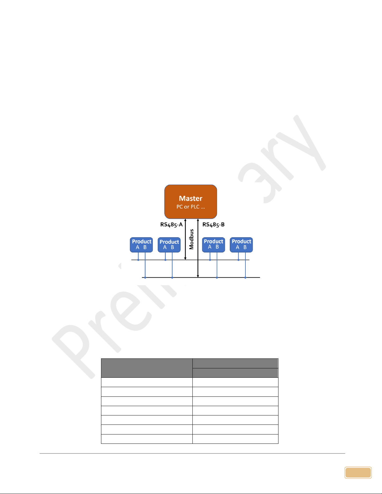
5.1.1 Hardware connection
The RS485 hardware layer is TIA/EIA-485-A, as illustrated below. In this configuration, the product
(FS4100) is a slave.
Figure 5.1: RS485 hardware
5.1.2 Communication parameters
The PC UART communication parameters are listed in table 5.1.
Table 5.1: PC UART communication parameters
Parameters
Protocol
RTU
Baud rate (Bits per second)
38400 bps
Start bits
1
Data bits
8
Stop bits
1
Even/Odd parity
None
Bits period
104.2 µsec
Bytes period
1.1458 msec
11
www.Siargo.com FS35001 User Manual
Maximum data length
20
Maximum nodes
247
5.1.3 Frame
The frame function is based on the standard Modbus RTU framing:
Table 5.2: frame function
Start_bits
Address
Function codes
Data
CRC
Stop_bits
T1-T2-T3-T4
8 bit
8 bit
N 8 bit (20≥n≥0)
16 bit
T1-T2-T3-T4
Start_bits: 4 periods bit time, for a new frame.
Address: The address can be set from 1 to 247 except for 157 (0x9d). 0 is the broadcast address.
Function codes: Define the product's functions/actions (slaves), either execution or response.
Data: The address of the register, length of data, and the data themselves.
CRC: CRC verification code. The low byte is followed by the high byte. For example, a 16-bit
CRC is divided into BYTE_H and BYTE_L. In the framing, the BYTE_L will come first, then
followed by the BYTE_H. The last one is the STOP signal.
Stop_bits: 4 periods bit time, for ending the current frame.
5.1.4 Function codes
The Modbus function codes applied for the product are the sub-class of the standard Modbus
function codes. These codes are used to set or read the registers of the product:
Table 5.3: function codes
Code
Name
Functions
0x03
Read register
Read register(s)
0x06
Set single register
Write one single 16-bit register
0x10
Set multiple registers
Write multiple registers
5.1.5 Registers
The product (FS4100) has multiple registers available for the assignment of the various functions. With these
functions, the user can obtain the data from the products, such as product address and flow rates from the
registers, or set the product functions by writing the corresponding parameters.
The currently available registers are listed in the following table, and the registers may be customized upon
contacting the manufacturer. Where R: read; W: write-only; W/R: read and write.

12
www.Siargo.com FS35001 User Manual
Note: At the time of shipping, the write protection function is enabled except for address and baud rate.
Once the user completes the register value change, the write protection will be automatically enabled
once again to prevent incidental data loss.
Table 5.4: Registers
Functions
Description
Register
Modbus
Address
Product address (R/W)
0x0081
40130 (0x0081)
Serial number
Serial number of the product (R)
0x0030
40049 (0x0030)
Flow rate
Current flow rate (R)
0x003A ~ 0x003B
40059 (0x003A)
Baud rate
Communication baud rate (R/W)
0x0082
40131 (0x0082)
GCF
Gas conversion factor (R/W)
0x008B
40140 (0x008B)
Digital filter depth
Response time or sampling time (R/W)
0x008C
40141 (0x008C)
Offset calibration
Offset reset or calibration (W)
0x00F0
40241 (0x00F0)
Write protection
Write protection of selected parameters (W)
0x00FF
40256 (0x00FF)
The detailed information of each register is described below: Y: enabled; N: disabled
Address
0x0081
Write
Y
Read
Y
Description
Address of the product
Value type
UINT 16
Notes
Values from 1 to 247 except for 157 (0x9d).
The broadcast address is not enabled, and the default address is 1.
SN, Serial number
0x0030
Write
N
Read
Y
Description
Series Number of the product, SN
Value type
UINT 8 (12 bits)
Notes
SN= value(0x0030), value(0x0031),….,value (0x0035);
Receiving 12 bits as: 2A 41 31 42 32 33 34 35 36 2A , the corresponding Serial
Number is **A1B23456**.
Flow rate
0x003A ~ 0x003B
Write
N
Read
Y
Description
Current flow rate
Value type
UINT 16
Notes
Flow rate = [Value (0x003A) * 65536 + value (ox003B)] / 1000
e.g.: When the user reads “0” from register 0x003A and “20340” from register
0x003B, current flow rate = (0 * 65536 + 20340) / 1000 = 20.340 SLPM
Baud rate
0x0082
Write
Y
Read
Y
Description
Communication baud rate
Value type
UINT 16

13
www.Siargo.com FS35001 User Manual
Notes
0: baud rate=4800; 1: baud rate=9600; 2: baud rate=19200; 3 baud rate=38400.
The default value is 3.
e.g.: When the user reads “3” from register 0x0082, the baud rate is 38400.
GCF
0x008B
Write
Y
Read
Y
Description
The gas conversion factor for applicable gas is different from calibration gas
Value type
UINT 16
Notes
The GCF of air is 1000 (default), normally read from register 0x008B.
Note: The product will disable this function with write protection once the
metering gas is confirmed with the proper GCF. For a specific GCF
value, please contact the manufacturer.
Response time
0x008C
Write
Y
Read
Y
Description
Digital filter depth setting
Value type
UINT 16
Notes
0 ~ 9 programmable, corresponding to 20~ 29data sampling in the software
filter.
The default value is 3, corresponding to 23= 8 data sampling.
Offset calibration
0x00F0
Write
Y
Read
N
Description
Reset or calibrate the offset
Value type
UINT 16, Fixed value 0xAA55
Notes
To reset or calibrate the offset, write 0xAA55 to register 0x00F0.
Note: When you execute this function, make sure there is NO flow in the
flow channel.
Write protection
0x00FF
Write
Y
Read
N
Description
Write protection disabler for a set value to a specific register.
Value type
UINT 16, Fixed value 0xAA55
Notes
This function is enabled at the time of product shipment. To enable the write
function of a specific parameter, such as GCF, or offset, the user needs to send
0xAA55 to the register 0x00FF, and then the write function will be enabled
(write protection is disabled). After the write execution is completed, the
firmware will automatically re-enable the write protection.

14
www.Siargo.com FS35001 User Manual
5.2 I2C communication protocol
5.2.1 I2C interface connection diagram
5.2.2 I2C interface read/write sequences
15
www.Siargo.com FS35001 User Manual
5.2.3 I2C interface command description
Please note the addition of the CRC in the protocol. If you are using an older version, you may need to update
your firmware for the current products.
Command
Byte
Length
(int 16)
Command Name
Read/Write
Notes
0x00A4
1
I2C address
Read/Write
Int 16.
bit 0 is the R/W flag bit;
bit 1 ~ bit 7 are available;
bit 8 ~ bit 15 = 0.
The default I2C address is 1.
Hex: 0x0002 (write) /0x0003 (read),
Bin: 0000 0000 0000 0010 (write)
0000 0000 0000 0011 (read).
0x0030
6
Sensor serial number
Read
ASCII
0x003A
2
Flow rate
Read
Int 32/1000 SLPM
0x008C
1
Filter depth
Read/Write
Int 16, 0 ~ 9, corresponding to 20~ 29
data in the software filter.
The default value is 3, corresponding
to 23= 8 data in the software filter
0x00F0
1
Reset the offset of
differential pressure
Write
Fixed value, 0xAA55
Note: The I2C address is set to bit7 ~ bit 1, e.g., if the I2C address is 1 (0000 001x), the write address will be
0x02 (0000 0010) and the read address will be 0x03 (0000 0011).
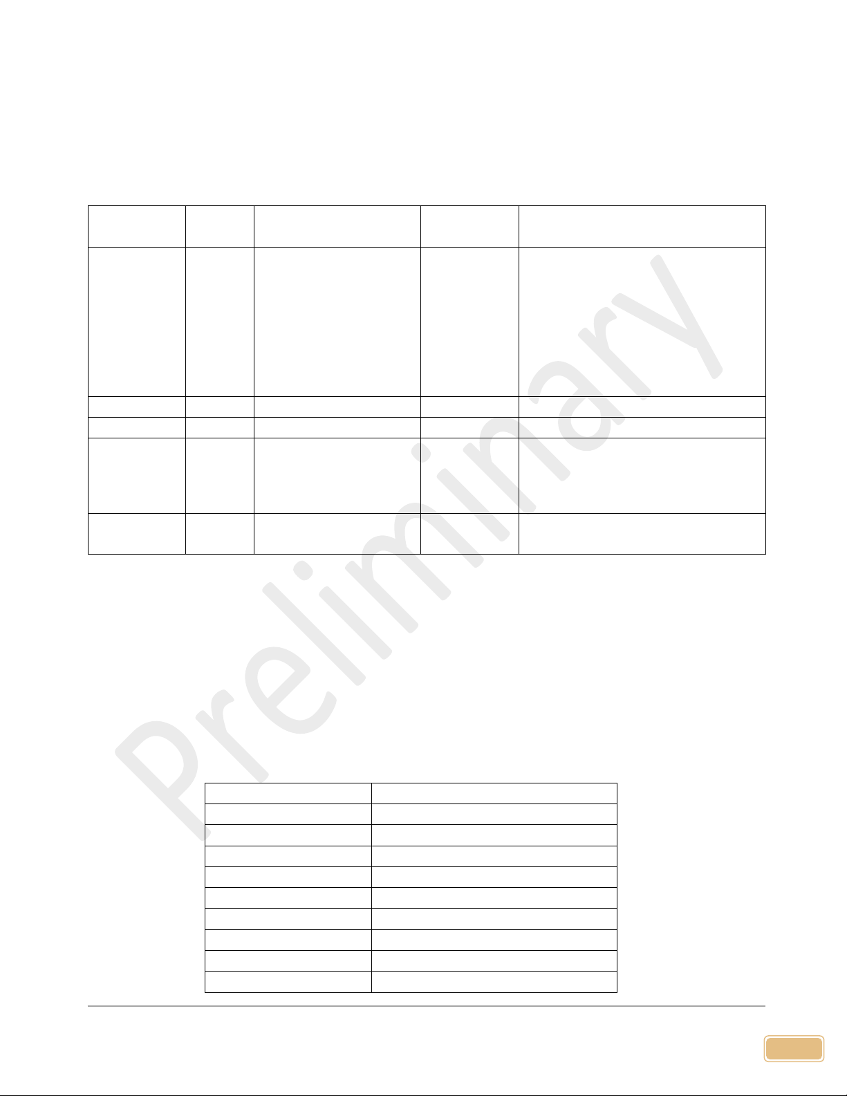
5.2.4 CRC checksum calculation
The 8-bit CRC checksum transmitted after each two data bytes (int 16) is generated by a CRC
algorithm. Its properties are listed in the table below. To calculate the checksum, only these two
previously transmitted data bytes are used.
Property
Value
Name
CRC-8
Protected data
I2C read and write
Width
8 bits
Polynomial
0x07 (x8 + x2 + x + 1)
Initialization
0x00
Reflect input
False
Reflect output
False
Final XOR
0x00
Example
CRC(0x4E20) = 0x6D

16
www.Siargo.com FS35001 User Manual
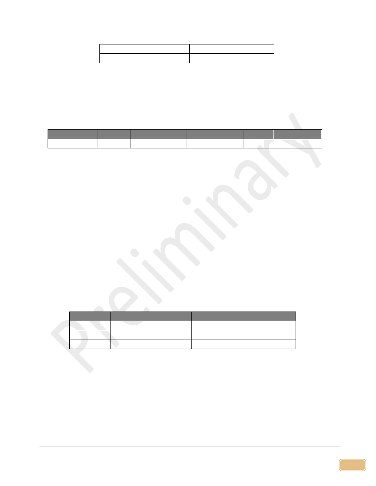
6. Product selection
The product part number is composed of the product model number and suffixes, indicating each
of the selectable parameters. Refer to the following for details.
FS35001 - -
Note: For CO2, the full-scale flow is 60% of the specified ones.
Gas: A –air; N2; O2; Ar; C –CO2; E –He; H –H2. For other
gases, please contact the manufacturer.
Output: V –analog; B –RS485 Modbus half plex; E –I2C;
Also available with BV, and EV.
Full scale flow rate: 200, 500, 1000, 2000, 4000, 6000, 10000,
15000, and 20000 sccm. For higher flow rate options, please
contact the manufacturer.

17
www.Siargo.com FS35001 User Manual
7. Product performance
7.1 Technical specifications
All specifications listed in the following table, unless otherwise noted, apply for calibration
conditions at 20°C and 101.325 kPa absolute pressure with air.
Value
Unit
Flow range
0 ~ 100…20000; or 0~±100 …±20000
sccm
Accuracy
±(1.5+0.5FS)
%
Repeatability
0.5
%
Turn-down ratio
100:1
Response time*
10
msec
Temperature range
-5 ~ 50
°C
Maximum pressure
1.0 (150)
MPa (psi)
Humidity
<95, no condensation
%RH
Analog null shift
±30
mV
Power supply
8 ~ 24
Vdc
Working current
50
mA
Output
Linear, analog 0.5 ~ 4.5 Vdc / Rs485 Modbus / I2C
Analog load
Sourcing: 25 / Sinking: 15
mA
Maximum overflow
3000 (3SLPM) (200, 500, 1000 models);
18000 (18 SLPM) (2000, 4000, 6000 models)
45000(45SLPM) (10000, 15000 models)
sccm (SLPM)
Maximum flow change
500 (200, 500, 1000 models);
3000 (2000, 4000, 6000 models)
7500(10000, 15000 models)
sccm/sec
Calibration
Air @ 20°C, 101.325 kPa
Storage temperature
-20 ~ +70
°C
Compliance
RoHS; REACH
CE
IEC 61000-4-2; 4-8
Wetted materials
Aluminum alloy; silicon nitride; Ablestik 84-3J; FR4
Note: 1. Allow the product to warm up for 60 seconds for the best performance.
2. Response time shown is the default. It can be programmed to the fastest <2 msec.
18
www.Siargo.com FS35001 User Manual
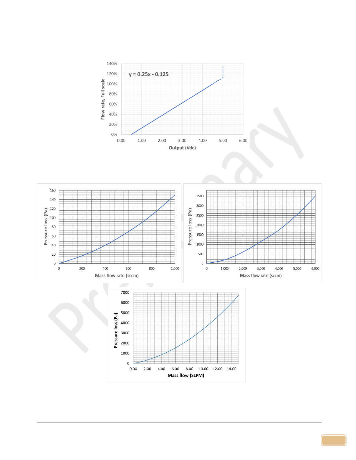
7.2 Typical (analog) output
Figure 7.1: Typical analog output
7.3 Pressure loss
Figure 7.2: Upper row: from left to right, for models of full scale up to 1000 sccm; and of full scale from 2000
to 6000 sccm. Lower row: models of full scale from 10000 to 15000 sccm (10 to 15SLPM).

19
www.Siargo.com FS35001 User Manual
8. Technical notes for the product performance
8.1 Measurement principles
The products utilize the Company’s proprietary micro-machined
(MEMS) calorimetric sensing with thermal diffusivity detection and
data process technology. A thermal signal generator with a pair of
sensing elements up and downstream of the micro heater is precisely
manufactured and separated at predefined micrometer distances on
a chip surface with excellent thermal isolation. When a fluid is
flowing through the sensing chip, the fluid carries the thermal signal
downstream. The sensing elements register the temperature
differences and measure the fluidic thermal diffusivity, further
correlated to the fluid mass flow rate via the calibration process.
Compared to the calorimetric sensing products offered by other
manufacturers on the market, the proprietary sensing approach
offers a large dynamic range with a better performance against the environmental parameter
alternations. It removes some gas sensitivities for gases with the same diffusivity and much-
improved the linearity when a gas conversion factor is used for the metering of the non-calibration
gases. Please refer to the company's US patents and other publications made available to the public
for additional information.
8.2 Precautions for the best performance of the product
8.2.1 Contamination and sterilization
It is critical to have the measurements performed in a contamination-free environment for data
accuracy. Excessive contaminants such as vapors will lead to data deviation or even product
malfunctions in severe cases.
For medical applications, it may be desired to have the product to be sterilized from time to time. A
standard EtO sterilization process is recommended. For the detailed procedure please consult your
local experts or contact the manufacturer.
8.2.2 Altitude changes
Figure 8.1: Illustration of
the measurement principle.
illustration.

20
www.Siargo.com FS35001 User Manual
Unlike some other products on market, the design of the sensor has a built-in pressure balancer that
prevents membrane deformation due to altitude changes. Therefore, the sensor is intrinsically
insensitive to altitude change-induced errors. The specified altitude in Sec 7.1 has been fully tested.
8.2.3 Excessive humidity or condensation
The humidity change will not alter the performance of the sensor. However, if excessive humidity is
present resulting in condensation, the measurement port or channel could be blocked or altered.
This would result in a very unreliable data output. Please filter or other tools to prevent this situation
to occur when using this product.
8.2.4 Metrology verification
Testing the products with local metrology tools will be performed in almost all cases. It should be
noted that for this particular sensor, special care should be applied while performing such a task.
The gauge pressure tests are relatively simple, as long as the pressure is tested under a stable media
condition, the metrology data should be well reproduced.
For the mass flowrate comparison, however, in addition to the flow system setup conditions
recommended by OIML R137, a stable flow system must be ensured. This is because the current
product is designed for a small pressure loss, therefore the sensor does not have a strong flow
restrictor or conditioners to handle the flow instability that may exist in the system. Therefore to
compare the metrology data, the user should ensure the system is stable, otherwise, the output
could be noisy and metrology deviations would be inevitable. If such cases are present, please
contact the manufacturer for further solutions.
For temperature and humidity measurement, because of the small package space, the response of
the humidity could be slower than specified. For additional information, please contact the
manufacturer.
Table of contents
Other Siargo Accessories manuals


