Siargo FS4100 Series User manual

FS4100
User Manual
MEMSmassflowsensors
©2021 SiargoLtd.
VA.0

www.Siargo.com
FS4100UserManual
1
|
Page
Gas Mass Flow Meter
withMEMSthermaltime‐of‐flightsensingtechnology
FS4100Series
User Manual
DocumentNo. 08‐2021‐FSN1EN
Issuedate: 2021.08
Revision: VA.0
SiargoLtd.
3100DeLaCruzBoulevard,Suite210
SantaClara,CA95054
USA
Tel:+1(408)969.0368
Email:[email protected]
©Copyright2021bySiargoLtd.
SiargoLtd.anditssubsidiariesreservetherighttochangethespecificationsand/ordescriptions
withoutpriornotice.Forfurtherinformationandupdates,pleasevisit:www.Siargo.com

www.Siargo.com
FS4100UserManual
2
|
Page
Attention!
Usewithcaution!
Pleasecarefullyreadthismanualpriortooperatingthisproduct.
Donotopenormodifyanyhardwarewhichmayleadtoirrecoverable
damage.
Donotusethisproductifyoususpectanymalfunctionsordefection.
Donotusethisproductforcorrosivemediaorinastrongvibration
environment.
Usethisproductaccordingtothespecifiedparameters.
Onlythetrainedorqualifiedpersonnelshallbeallowedtoperform
productservices.
Becautiousfortheelectricalsafety,evenitoperatesatalowvoltage,
anyelectricalshockmightleadtosomeunexpecteddamages.
Thegastobemeasuredshouldbecleanandfreeofparticles.Donotapply
thismeterforliquidmedium.
Donotapplyforanyunknownornon‐specifiedgasesthatmay
damagetheproduct.
Forremotedata,pleasebesurethemeterisproperlyconfigured.

www.Siargo.com
FS4100UserManual
3
|
Page
TableofContents
1.Overview..................................................................................................5
2.Receipt/unpackoftheproducts................................................................6
3.Knowingtheproducts...............................................................................7
3.1.Productdescription.................................................................................................7
3.2.Poweranddatacabledescription.............................................................................7
3.3.Mechanicaldimensions............................................................................................8
4.Installation...............................................................................................9
5.Operation................................................................................................11
5.1Checktheproductspecifications............................................................................11
5.2Checktheleakage.................................................................................................11
5.3Powertheproductanddigitaldataconnection........................................................11
5.4RS485Modbuscommunicationprotocol.................................................................12
5.4.1Hardwareconnection......................................................................................12
5.4.2Communicationparameters..........................................................................................12
5.4.3Frame............................................................................................................13
5.4.4Functioncodes................................................................................................13
5.4.5Registers........................................................................................................13
5.5Analogoutput(0.5~4.5Vdc).................................................................................16
5.6Pressureloss.........................................................................................................16
6.Productselectionandorderinformation...................................................18
6.1Productselection..................................................................................................18
6.2Ordercontactandcustomersupport.......................................................................18
7.Technicalspecifications............................................................................19

www.Siargo.com
FS4100UserManual
4
|
Page
8.Technicalnotesfortheproductperformance.............................................20
8.1Measurementprinciple..........................................................................................20
8.2Precautionsforthebestperformanceoftheproduct................................................20
8.2.1Comparisonwithathirdpartyreferencemeter...............................................................20
8.2.2Particlecontaminationandfluidiccleanness..................................................................21
8.2.3Applytoadifferentgasmedium....................................................................................21
9.Troubleshooting......................................................................................22
10.WarrantyandLiability..............................................................................23
11.Servicecontact........................................................................................25
AppendixI:Productevaluationkit.................................................................26
AppendixII:Documenthistory.......................................................................27

www.Siargo.com
FS4100UserManual
5
|
Page
1. Overview
Allcontactinformationcanbefoundattheendofthismanual.
ThismanualprovidesessentialinformationfortheoperationoftheFS4100seriesofgasmassflow
sensorsforgeneral‐purposegasflowmonitorandcontrolapplicationswiththefull‐scalemassflow
ratefrom2to50SLPM,andbothanaloganddigitaloutputs.Theproductperformance,maintenance,
andtrouble‐shootingaswellastheinformationforproductorder,technicalsupport,andrepairare
alsoincluded.
FS4100massflowsensorsareanupgradedversionorthethirdgenerationoftheFS4000sensors
releasedin2008.Itcanbeappliedformedicalequipmentsuchasanesthesiaapplication,endoscope,
andcancertreatment;industrialapplicationsincludingweldingmachine,laserequipment,gas
mixture;andmanymore.Theseriescoversawidedynamicflowrangewithaworkingpressurerating
ofupto0.5MPa(5baror73PSI),andacompensatedtemperaturerangingfrom‐10to55°C.
Theproductsaredesignedwithaneasychangeofmechanicalconnectors.Thestandardconnectors
areBSPT1/4”orone‐touchconnector,andothercustomizedonesareavailableuponrequest.
TheproductsareoperatedwithSiargo’sproprietaryMEMSthermaltime‐of‐flightsensing
technologytogetherwithsmartcontrolelectronics.Thesensorsurfaceispassivatedwithsilicon
nitrideceramicmaterialstogetherwithawater/oilproofnano‐coatingforperformanceand
reliability.Comparedtothepreviouscalorimetricflowsensingtechnology,thisuniquesensing
approachoffersabetterlinearity,removesgassensitivityforgaseswithsimilarthermaldiffusivities,
andimprovesthetemperatureperformance.Therefore,itisthefirstofthekindintheindustrythat
sensesthemassflowwithmultiplegaseswithoutchangingthegasconversionfactor.Assuch,it
ensuresthehighprecisionforgasmeasurementswithaircalibration.
Thecurrentproductisalsohasamuchsmallerformfactorcomparedtothepreviousversions.

www.Siargo.com
FS4100UserManual
6
|
Page
2. Receipt/unpackoftheproducts
Uponreceiptoftheproducts,pleasecheckthepackingboxbeforethedismantlementofthepacking
materials.Ensurenodamagesduringshipping.Ifanyabnormalityisobserved,pleasecontactand
notifythecarrierwhoshippedtheproductandinformthedistributorsorsalesrepresentativesifthe
orderisnotplaceddirectlywiththemanufacturer,otherwise,themanufacturershouldbeinformed
aswell.Foranyfurtheractions,pleaserefertothereturnandrepairsectioninthismanual.
Ifthepackingboxisintact,proceedtoopenthepackingbox,andyoushallfindtheproduct.The
poweranddatacable(partnumber:SN5‐50)asshownbelowmayalsobefoundaccordingtothe
samepackingmaterials.
Figure2.1:FS4100flowsensorFigure2.2:poweranddatacableSN5‐50
Pleasecheckimmediatelyfortheintegrityoftheproductaswellasthepoweranddatacable,ifany
abnormalisidentified,pleasenotifythedistributor/salesrepresentativeormanufacturerassoonas
youcan.Ifanydefectsareconfirmed,anexchangeshallbearrangedimmediatelyviatheoriginal
saleschannel.Thisusermanualshallalsoeitherbeincludedinthepackingboxorviaanonline
requestforanelectronicversion.Inmostcases,thismanualshallbemadeavailabletothecustomer
beforetheactualorder.
Thestandardcable(partnumber:SN5‐50)hasanAMPMODUMTE(5positions)compatible
connectorwithalengthof0.5meters.

www.Siargo.com
FS4100UserManual
7
|
Page
3. Knowingtheproducts
3.1. Productdescription
Figure3.1:FS4100partsdescription
3.2. Poweranddatacabledescription
Table3.1:FS4100pin/wireassignments.
Figure3.2:FS4100connectionandcable
Note:
1.Thestandardcable(partnumber:SN5‐50)hasanAMPMODUMTE(5positions)compatible
connectorwithalengthof0.5meters.
2.TheRS485Modbusisasynchronous,half‐duplexcommunication.Whenthedataaretransmitted
orreceivedfromtheproduct,theotherpinisservingastheground.
Wire Color Definition
1
Blue
B
(RS485)
/SDA(I
2
C)
2GreenAnalogoutput,0.5~4.5Vdc
3RedPowersupply,8~24Vdc
4BlackGround
5YellowA(RS485)/SCL(I
2
C)
Exchangeable
connector
Excahngeable
Connector,inlet
Flowdirection
Electricalinterface,AMP
MTE,5positions
Meterbody
Installationscrews(M3X4)
www.Siargo.com
FS4100UserManual
8
|
Page
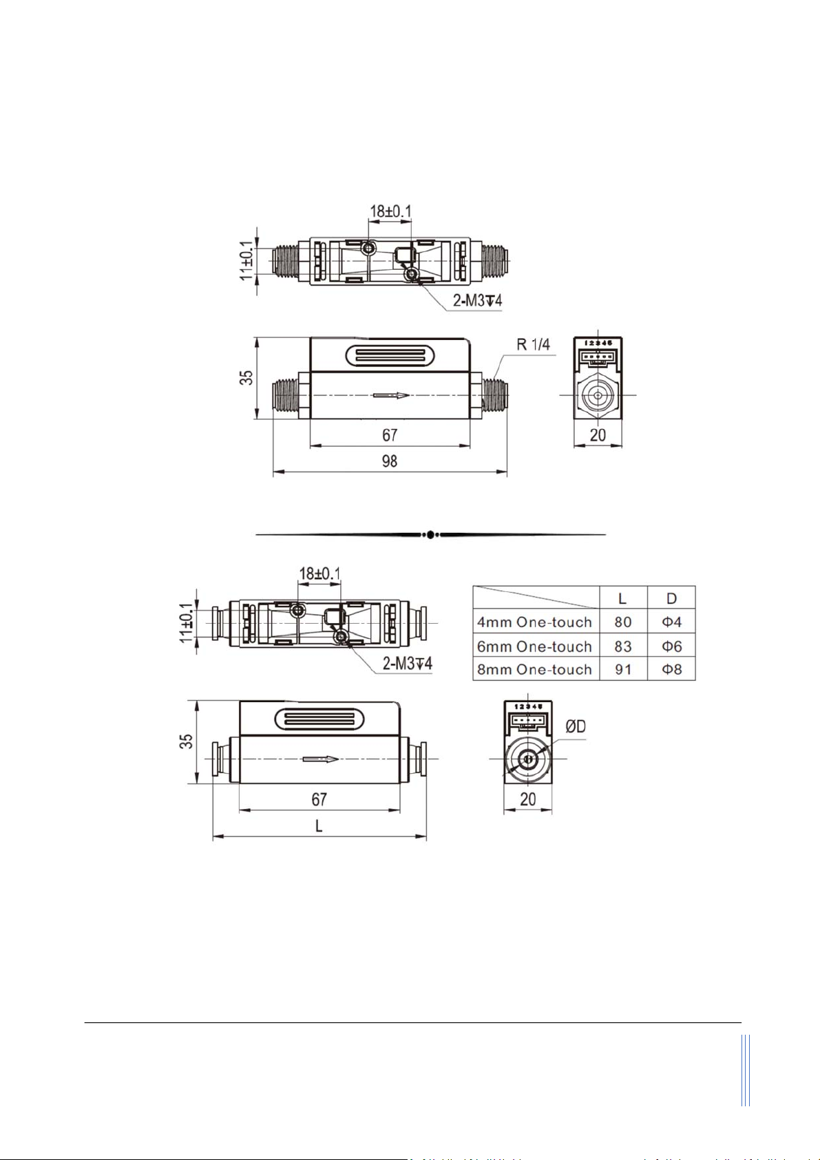
3.3. Mechanicaldimensions
Figure3.3:FS4100dimensionswithBSPT1/4”(R1/4”)connectors
Figure3.4:FS4100dimensionswithone‐touchconnectors
Note: *Otherthreadsorcompressivetypescanbecustomized.
**Themountingscrewlength<4mm;andthesuggestedmountingtorque<0.25N∙m.

www.Siargo.com
FS4100UserManual
9
|
Page
4. Installation
Donotopenoralteranypartoftheproductwhichwouldleadtomalfunctionandirrecoverable
damage.Itwillalsoforfeitthetermsofthewarrantyandcauseliability.
Theproductatthetimeofshipmentisfullyinspectedforitsqualityandmeetsallsafetyrequirements.
Additionalsafetymeasuresduringtheinstallationshouldbeapplied.Thisincludes,butisnotlimited
totheleakageverificationprocedures,standardEDS(electrostaticdischarge)precautions,DC
voltageprecautions.Othertaskssuchascalibration,partreplacement,repair,andmaintenance
mustonlybeperformedbytrainedpersonnel.Uponrequest,themanufacturerwillprovide
necessarytechnicalsupportand/ortrainingofthepersonnel.
Therearenopreferredspacedirectionsfortheinstallation.Flowdirectionshouldbealignedwiththe
arrowmarkonthemeterbody.Iftheflowingfluidmayhaveparticlesordebris,afilterisstrongly
recommendedtobeinstalledupstreamofthemeter.
Pleasefollowthefollowingstepstocompletetheinstallation:
a)Uponopeningthepackage,theproduct'sphysicalintegrityshouldbeinspectedtoensureno
visualdamage.
b)Beforeinstallationoftheproduct,pleaseensurethatthepipedebrisorparticlesoranyother
foreignmaterialsarecompletedremoved.
c)Closetheupstreamvalve,ifany,completely.
d)Duringinstallation,pleasemakesurenoforeignmaterials(suchaswater,oil,dirt,particles,etc.)
enteringintotheinstallationpipeline.
e)ConnectelectricalwiresperthewiredefinitioninTable3.1.Pleasebesureofthepowersupply
range(i.e.,8~24VDC)andpowersupplypolarization.Ifanadapterisused,makesurethe
adaptermeetsindustrialstandardsandhasallsafetycertifications.Alternatively,thisproduct
canalsobepoweredbya9Vdcbattery.
f)Forthedatacommunicationwireconnection,pleasefollowthedescriptioninTable3.1andmake
surethatthewiresarecorrectlyconnectedtotheproperportsonyourdatadevice/equipment.
Pleasemakesurethedatacablemeetsindustrialstandardswithpropershielding.
g)Slowlyopenthevalve(s)ofthegassupplyifany,upstreamordownstream,orbothofthe
pipeline.theproductshouldthenstarttomeasuretheflowinthepipeline.
Note:becausethemeterhasalargedynamicalmeasurementrange,itcouldbenormalif
youseethesmallinstantflowrateevenifthereis“no‐flow”inthepipeline.Ifthe
valueconsistentlypresent,double‐checkthepipeleakageandthenresettheoffsetif
youaresurethereisnoleakageorflow.
h)Thiswillconcludetheinstallation.

www.Siargo.com
FS4100UserManual
10
|
Page
Cautions
a)Don'talteranypartsoftheproduct.
b)Ensuretheelectricalconnectionisproperlydonepertheinstructions.
c)Makesurenomechanicalstressesintheconnections.
d)Thestrongelectromagneticinterferencesourcesclosebyoranymechanicalshocksatthe
pipelinemayalsocreatemalfunctioningoftheproduct.
e)Slowlyopen/closevalvesatthegassupplypipingtopreventabruptpulseflowimpact.

www.Siargo.com
FS4100UserManual
11
|
Page
5. Operation
5.1 Checktheproductspecifications
Beforestartingtousethisproduct,checktheproductspecificationsthatcanbefoundinthismanual
orthebasicinformationfromthedatasheetatthecompany’swebsitewww.Siargo.com.
ThedetailedproducttechnicalspecificationscanbefoundinSection7.Foraspecificapplication,
thepressureratingmustnotbehigherthanthesystempressuretobemeasured,andtheflowrange
shouldalsobewithinthespecifiedones.Inmostcases,theuseofahighfull‐scalerangedmeterfor
theverylowflowratemeasurementoftenresultsinerroneousdata.Thegastobemeasuredmust
alsobeconsistentwiththatspecifiedbytheproduct.Beparticularlycautiousaboutthesupplied
voltageindicatedinthespecification.Ahighervoltagemayleadtoirrecoverabledamage,anda
lowervoltagewillnotpowertheproductforanydesiredfunctions.
Forthebestperformanceoftheproduct,itisadvisedthatthegastobemeasuredmustbecleanand
freeofparticlesorotherforeignmaterials.
5.2 Checktheleakage
Checkgasleakagebeforeanymeasurement.Ifitisneeded,thepressurizednitrogenoraircanbe
usedfortheleakagecheck.
5.3 Powertheproductanddigitaldataconnection
AlthoughthisproductcomplieswiththeCE‐requiredEMCregulations,italsorequirestheproductto
beusedaccordingtothestandardelectricaldevicepractice.Beforeconnectingtheproductwith
externalDCpoweroranAC‐DCadapter,makesurethesupplyvoltageiswithintherangeofthe
specifiedonesinSection7.BecautiousthatthestandardelectricaldeviceprecautionssuchasEDS
(electrostaticdischarge)andDCvoltageareobserved.Excessiveelectrostaticdischargemay
damagetheproduct.
Themanufacturer‐suppliedpoweranddatacablehavealockingfixture.Lockthecableandmake
sureitisproperlyengagingandwillnotbeaccidentallygotunplugged.
Half‐duplexRS485Modbusisusedfordigitaldatacommunication.Makesurethewiresareproperly
connectedtothereceiverside.

www.Siargo.com
FS4100UserManual
12
|
Page
5.4 RS485Modbuscommunicationprotocol
ThedigitalcommunicationprotocolisbasedonstandardModbusRTUHalf‐plexmode.Amaster(PC
orPLC)cancommunicatewithmultipleslaves(thecurrentproduct)fordataexchangeand
communicationparameterconfiguration.RefertoTable3.2forcableconnection.
5.4.1 Hardwareconnection
TheRS485hardwarelayerisTIA/EIA‐485‐A,asillustratedbelow.Inthisconfiguration,theproduct
(FS4100)isaslave.
Figure5.1:RS485hardware
5.4.2 Communicationparameters
ThePCUARTcommunicationparametersarelistedintable5.1.
Table5.1:PCUARTcommunicationparameters
ParametersProtocol
RTU
Baudrate(Bitspersecond)
38400bps
Startbits1
Databits8
Stopbits1
Even/OddparityNone
Bitsperiod104.2µsec
Bytesperiod1.1458msec
Maximumdatalength
20
Maximumnodes254

www.Siargo.com
FS4100UserManual
13
|
Page
5.4.3 Frame
TheframefunctionisbasedonthestandardModbusRTUframing:
Table5.2:framefunction
Start_bitsAddress
Functioncodes
DataCRCStop_bits
T1‐T2‐T3‐T48bit8bitN8bit(20≥n≥0)
16bitT1‐T2‐T3‐T4
Start_bits:4periodsbittime,foranewframe.
Address: Theaddresscanbesetfrom1to255exceptfor157(0x9d).0isthebroadcastaddress.
Functioncodes: Definetheproduct'sfunctions/actions(slaves),eitherexecutionorresponse.
Data: Theaddressoftheregister,lengthofdata,andthedatathemselves.
CRC: CRCverificationcode.Thelowbyteisfollowedbythehighbyte.Forexample,a16bit
CRCisdividedintoBYTE_HandBYTE_L.Intheframing,theBYTE_Lwillcomefirst,then
followedbytheBYTE_H.ThelastoneistheSTOPsignal.
Stop_bits: 4periodsbittime,forendingthecurrentframe.
5.4.4 Functioncodes
TheModbusfunctioncodesappliedfortheproductarethesub‐classofthestandardModbus
functioncodes.Thesecodesareusedtosetorreadtheregistersoftheproduct:
Table5.3:functioncodes
CodeNameFunctions
0x03ReadregisterReadregister(s)
0x06Setsingleregister
Writeonesingle16‐bitregister
0x10Setmultipleregisters
Writemultipleregisters
5.4.5 Registers
Theproduct(FS4100)hasmultipleregistersavailablefortheassignmentofthevariousfunctions.Withthese
functions,theusercanobtainthedatafromtheproducts,suchasproductaddressandflowratesfromthe
registers,orsettheproductfunctionsbywritingthecorrespondingparameters.
Thecurrentlyavailableregistersarelistedinthefollowingtable,andtheregistersmaybecustomizedupon
contactthemanufacturer.WhereR:read;W:write‐only;W/R:readandwrite.
Note:Atthetimeofshipping,thewriteprotectionfunctionisenabledexceptforaddressandbaudrate.
Oncetheusercompletestheregistervaluechange,thewriteprotectionwillbeautomaticallyenabled
onceagaintopreventincidentaldataloss.

www.Siargo.com
FS4100UserManual
14
|
Page
Table5.4:Registers
FunctionsDescriptionRegisterModbus
Address Productaddress(R/W)0x008140130(0x0081)
SerialnumberSerialnumberoftheproduct(R)0x003040130(0x0030)
FlowrateCurrentflowrate(R)
0x003A
~
0x003B40059(0x003A)
BaudrateCommunicationbaudrate(R/W)0x008240131(0x0082)
GCFGasconversionfactor(R/W)0x008B40140(0x008B)
ResponsetimeResponsetimeorsamplingtime(R/W)0x008D40142(0x008D)
OffsetcalibrationOffsetresetorcalibration(W)0x00F040241(0x00F0)
WriteprotectionWriteprotectionofselectedparameters(W)
0x00FF40256(0x00FF)
Thedetailedinformationofeachregisterisdescribedbelow:Y:enabled;N:disabled
Address0x0081WriteY
ReadY
DescriptionAddressoftheproduct
ValuetypeUINT16
NotesValuesfrom1to255exceptfor157(0x9d).
0isthebroadcastaddress.
SN,Serialnumber0x0030WriteN
ReadY
DescriptionSeriesNumberoftheproduct,SN
ValuetypeUINT8(12bits)
Notes
SN=value(0x0030),value(0x0031),….,value(0x0035);
Receiving12bitsas:2A2A41314232333435362A2A,thecorresponding
SerialNumberis**A1B23456**.
Flowrate0x003A~0x003BWriteN
Read
Y
DescriptionCurrentflowrate
ValuetypeUINT16
Notes
Flowrate=[Value(0x003A)*65536+value(ox003B)]/1000
e.g.:Whentheuserreads“0”fromregister0x003Aand“20340”fromregister
0x003B,currentflowrate=(0*65536+20340)/1000=20.340SLPM
Baudrate0x0082WriteY
ReadY
DescriptionCommunicationbaudrate
ValuetypeUINT16
Notes
0:baudrate=4800;1:baudrate=9600;2:baudrate=19200;3baudrate=38400.
Thedefaultvalueis3.
e.g.:Whentheuserreads“3”fromregister0x0082,thebaudrateis38400.

www.Siargo.com
FS4100UserManual
15
|
Page
GCF0x008BWriteY
ReadY
DescriptionThegasconversionfactorforusingwithgasdifferentfromcalibrationgas
ValuetypeUINT16
Notes
TheGCFofairis1000(default),normallyreadfromregister0x008B.
Note:Theproductwilldisablethisfunctionwithwriteprotectiononcethe
meteringgasisconfirmedwiththeproperGCF.ForaspecificGCF
value,pleasecontactthemanufacturer.
Responsetime0x008DWriteY
Read
Y
DescriptionMeterresponseordatasamplingtime
ValuetypeUINT16
NotesThedefaultvalueis10(10msec).Optionsare10,20,50,100,and200msec.
Offsetcalibration0x00F0WriteY
ReadN
DescriptionResetorcalibratetheoffset
ValuetypeUINT16,Fixedvalue0xAA55
Notes
Toresetorcalibratetheoffset,write0xAA55toregister0x00F0.
Note:Whenyouexecutethisfunction,makesurethereisNOflowinthe
flowchannel.
Writeprotection0x00FFWriteY
ReadN
DescriptionWriteprotectiondisablerforasetvaluetoaspecificregister.
ValuetypeUINT16,Fixedvalue0xAA55
Notes
Thisfunctionisenabledatthetimeofproductshipment.Toenablethewrite
functionofaspecificparameter,suchasGCF,offset,theuserneedstosend
0xAA55totheregister0x00FF,andthenthewritefunctionwillbeenabled
(writeprotectionisdisabled).Afterthewriteexecutioniscompleted,the
firmwarewillautomaticallyre‐enablethewriteprotection.
www.Siargo.com
FS4100UserManual
16
|
Page
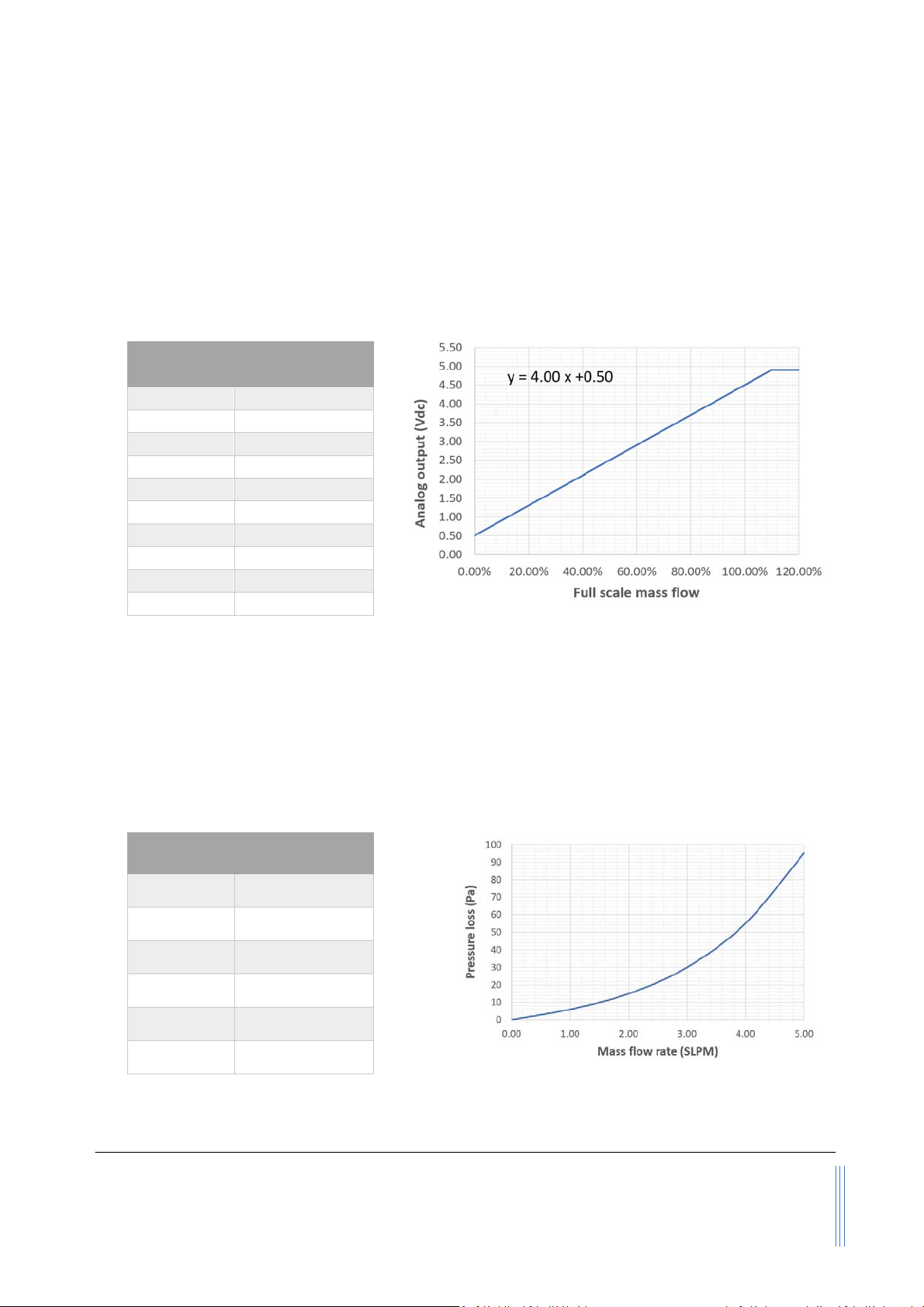
5.5 Analogoutput(0.5~4.5Vdc)
Theproductoffersavoltageanalogoutputoftheinstantflowrate.RefertoTable5.5forthewire
connectionforthisoutput.Themeteriscalibratedto110%ofthespecifiedfull‐scaleflowrate.The
typicalanalogoutputisindicatedbelow.Thisoverrangeappliestobothanaloganddigitaloutput.
Table5.5:FS4100analogoutput
Figure5.2:FS4100analogoutput
5.6 Pressureloss
Theproductisdesignedforlow‐pressureloss.Themajordropofthepressureisatthemanualvalve
structure.Thefollowinggraphillustratedthepressurelossesoftheselectedmodels.
Table5.6:FS4103pressureloss
Flowrate
(SLPM)
Pressureloss
(Pa/PSI)
0.00/o
1.06/0.001
2.015/0.002
3.030/0.004
4.055/0.008
5.095/0.014
Figure5.3:FS4103pressureloss
FlowrateAnalogoutput
(Vdc)
00.50
10%F.S.0.90
20%F.S.1.30
40%F.S.2.10
50%F.S.2.50
70%F.S.3.30
90%F.S.4.10
100%F.S.4.50
110%F.S.4.90
120%F.S.4.90
www.Siargo.com
FS4100UserManual
17
|
Page
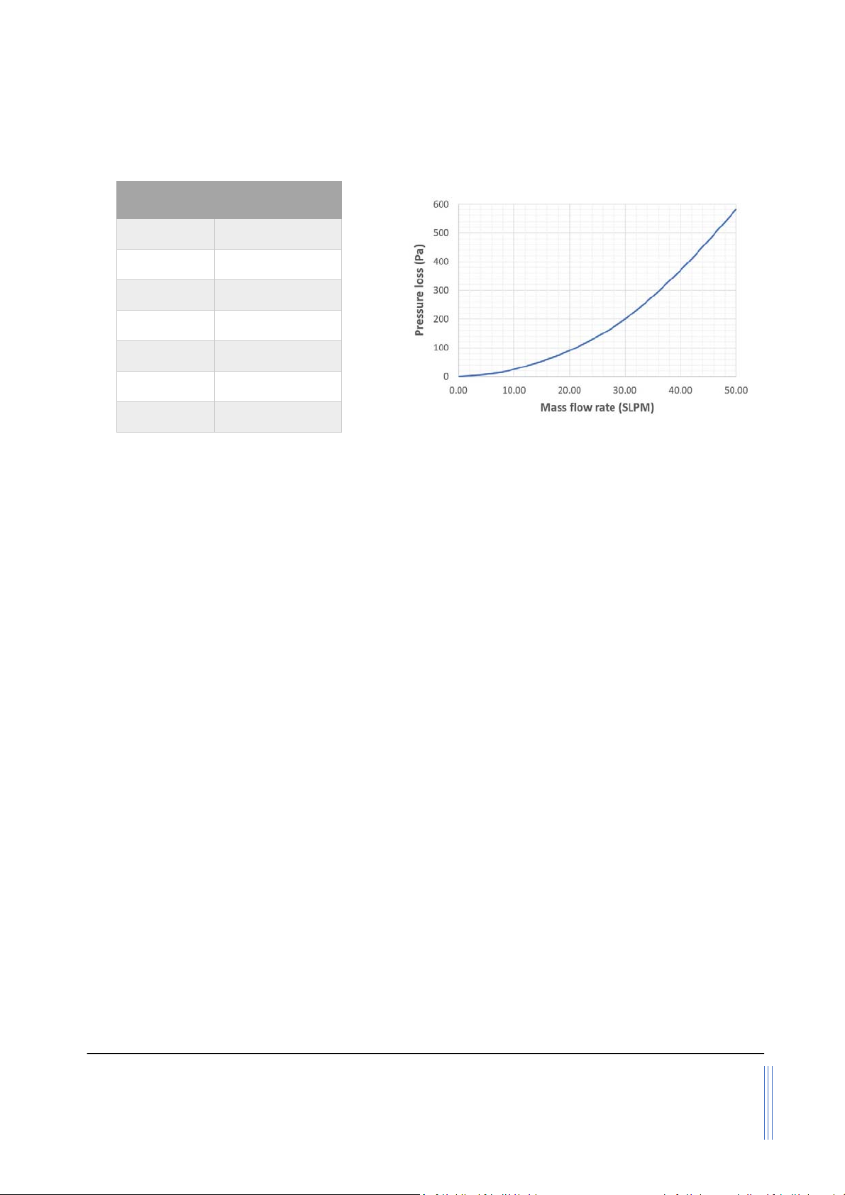
Table5.7:FS4108pressureloss
Flowrate
(SLPM)
Pressureloss
(Pa/PSI)
0.00/o
5.08/0.001
10.025/0.004
20.090/0.013
30.0200/0.029
40.0370/0.054
50.0580/0.084
Figure5.4:FS4108pressureloss

www.Siargo.com
FS4100UserManual
18
|
Page
6. Productselectionandorderinformation
6.1 Productselection
Theproductpartnumberiscomposedoftheproductmodelnumberandsuffixesindicatingthefull‐
scaleflowrate,aswellastheotherparameters.Refertothefollowingfordetails.
FS41‐‐‐‐
6.2 Ordercontactandcustomersupport
Thesalesofficesandthesalesdistributors/representativesarelistedattheendofthisdocument.For
smallquantities,theordercanbeplacedeitherthroughtheSiargowebsite:www.siargo.comorthe
salesoffice.Forlargequantities,pleasecontactthesalesoffice,distributors,orsalesrepresentatives.
Siargoismakingeveryefforttoensurethequalityoftheproducts.Incaseofquestionsand/or
productsupports,pleasecontactthecustomerservicelistedattheendofthedocument.
Gas(A–air;B–N2O;C–CO2,N–N2,O–O2,R–Ar;
forothergases,pleasecontactthemanufacturer.
Output(B–RS485;E–I2C;V–0.5~4.5Vdc.
Available:
B
,
E
,
BV
,
EV.
)
Maximumfullscaleflowrate(forthevaluereferto
thetablebelow).IftheunitisnotSLPM,theunit
needstobespecifiedhere.
Mechanicalconnection(R‐R1/4”;O4/O6/O8one‐touch
FS4103:R,O4,O6,O8available
FS4108:R.one‐touchisnotrecommended.)
DN(pipediameter:
03
or
08)

www.Siargo.com
FS4100UserManual
19
|
Page
7. Technicalspecifications
Allspecificationslistedinthefollowingtableunlessotherwisenotedapplyforcalibrationconditionsat20°C
and101.325kPaabsolutepressurewithair.Theproductishorizontallymountedatthetimeofcalibration.
ValueUnit
Full‐scaleflowrange2,3,4,5(FS4103)/10,20,30,40,50(FS4108)
Accuracy±(1.5+0.2FS)%
Repeatability0.25%
Turn‐downratio100:1
Workingtemperature‐10~55°C
Maximumpressure0.5MPa
Responsetime10(default,20,50,100,200,500,1000programmable)msec
Filterdepth0(default,4~255programmable)msec
Humidity<95,nocondensation%RH
Powersupply8~24(50mA)Vdc
Analogoutput0.5~4.5Vdc
Maximunullshift(analog)±30mVdc
AnalogoutputloadSourcing:14;Sinking:11mA
DigitaloutputRS485(Modbus)/I2C
Max.overflow30(FS4103)/200(FS4108)SLPM
Max.flowchange4(FS4103)/30(FS4108)SLPM/sec
ElectricalconnectorAMPMODUMTE5positions
MechanicalconnectionBSPTor4mm/6mm/8mmOne‐touch
ProtectionIP40
Storagetemperature ‐20~70°C
Referenceconditions20°C,101.325kPa,air
FluidcompatibilityNon‐corrosive
CEEN61000‐2;‐3;‐4
RoHS/REACHCertified
This manual suits for next models
2
Table of contents
Other Siargo Accessories manuals


Popular Accessories manuals by other brands


Aeotec
Aeotec Water Sensor 7 Pro user manual

Alphacool
Alphacool Core M.2 NVMe PCIe 4.0 manual

Logitech
Logitech Folio i5 Setup guide

Smart Technologies
Smart Technologies Hawkeye 480C Installation and user guide

HumanTechnik
HumanTechnik A-2656-0 user manual

C.P. Electronics
C.P. Electronics SPIR-F installation guide

SkyBound
SkyBound 2 ARCH TRAMPOLINE NET Assembly and installation manual

Haws
Haws 7501BLH Installation, operation & maintenance instructions

Summit Treestands
Summit Treestands SU82099 manual

Sun Power
Sun Power CryoTel Series operating instructions

Anritsu
Anritsu MA24 A Series Operation manual

SICK
SICK TiM8 DistanceGuard Series operating instructions