Siargo FS4001 User manual

FS4001 User Manual
MEMS mass flow sensors
©2021 Siargo Ltd.
VB.0.1
Sold in North America by:
Servoflo Corporation
75 Allen Street
Lexington, MA 02472
www.servoflo.com/info@servoflo.com
781-862-9572

2
www.Siargo.com FS4001 User Manual
MEMS Mass Flow Sensors
with thermal calorimetric sensing technology
FS4001 Series
User Manual
Document No. 07-2021-FS8 EN
Issue date: 2021.07
Revision: VC.0.1
Siargo Ltd.
3100 De La Cruz Boulevard, Suite 210
Santa Clara, California 95054
USA
Tel: +1(408)969.0368
© Copyright 2021 and Liability Disclaimer
Siargo Ltd. and its subsidiaries reserve the right to change the specifications and/or descriptions
without prior notice. Siargo and its subsidiaries shall not assume any inaccuracy or errors in this
manual. For further information and updates, please visit www.Siargo.com.

3
www.Siargo.com FS4001 User Manual
Attention !
Use with caution !
•Please carefully read this manual prior to operating this product.
•Do not open or modify any hardware which may lead to irrecoverable
damage.
•Do not use this product if you suspect any malfunctions or defection.
•Do not use this product for corrosive media or in a strong vibration
environment.
•Use this product according to the specified parameters.
•Only the trained or qualified personnel shall be allowed to perform
product services.
•Be cautious for electrical safety, and even it operates at a low voltage,
any electrical shock might lead to some unexpected damages.
•The gas to be measured should be clean and free of particles, as
even light particles may be accumulated inside the tiny pressure port
that may result in inaccuracy in metrology, clogging, or other
irrecoverable damage.
•Do not apply for any unknown or non-specified gases that may
damage the product.

4
www.Siargo.com FS4001 User Manual
Table of Contents
1. Overview ......................................................................................................................................................5
2. Receipt / unpack of the products ...............................................................................................................6
3. Knowing the products.................................................................................................................................7
3.1 Product description.............................................................................................................................7
3.2 Power and data pinout description ...................................................................................................7
3.3 Mechanical dimensions.......................................................................................................................8
4. Installation.......................................................................................................................................................8
5. Digital communication descriptions..............................................................................................................9
5.1 I2C interface...............................................................................................................................................9
5.1.1 I2C interface connection diagram.....................................................................................................9
5.1.2 I2C interface command description...................................................................................................9
5.1.3 I2C interface read/write sequences.................................................................................................10
5.2. RS232 communication protocol...........................................................................................................11
6. Product selection and order information....................................................................................................13
6.1. Product selection ...................................................................................................................................13
6.2. Order contact and customer support..................................................................................................13
7. Product performance ....................................................................................................................................14
7.1. Technical specifications.........................................................................................................................14
7.2. Analog output.........................................................................................................................................15
8. Technical notes for the product performance ............................................................................................16
8.1. Measurement principles ........................................................................................................................16
8.2. Precautions for the best performance of the product .......................................................................16
8.2.1. Altitude changes .............................................................................................................................16
8.2.2. Excessive humidity or condensation.............................................................................................16
8.2.3. Metrology verification....................................................................................................................17
9. Warranty and Liability..................................................................................................................................18
10. Service contact and information................................................................................................................20
Appendix I: Sensor evaluation kit....................................................................................................................21
Appendix II: Document history........................................................................................................................22

5
www.Siargo.com FS4001 User Manual
1. Overview
All contact information can be found at the end of this manual.
This manual provides essential information for the FS4001 series of mass flow sensors for testing,
leakage detection, instrumentation as well as medical applications. The product performance,
maintenance, and troubleshooting, as well as the information for product order, technical support,
and repair, are also included.
The FS4001 sensors are manufactured with the company’s proprietary MEMS (micro-electro-
mechanical systems) sensing and package technology that offers primarily the mass flow rate
measurements of a full scale from 30 to 1000 sccm with a dynamic range of 100:1, and the maximum
pressure rating of 5 bar (75 psi).

6
www.Siargo.com FS4001 User Manual
2. Receipt / unpack of the products
Upon receipt of the products, please check the packing box before the dismantlement of the packing
materials. Ensure no damages during shipping. If any abnormality is observed, please contact and
notify the carrier who shipped the product and inform the distributors or sales representatives if the
order is not placed directly with the manufacturer; otherwise, the manufacturer should be informed.
For any further actions, please refer to the return and repair section in this manual.
If the packing box is intact, proceed to open the packing box, and you shall find the product (either
the sensor formality per the actual order), together with the power and data cable if the order is
included as shown below.
Please check immediately for the integrity of the product and the power and data cable; if any
abnormality is identified, please notify the distributor/sales representative or manufacturer as soon
as you can. If any defects are confirmed, an exchange shall be arranged immediately via the original
sales channel. This user manual shall also be included in the packing box or via an online link for an
electronic version which should be sent by your sales agent. In most cases, this manual shall be made
available to the customer before the actual order.
Please note that the sensor has a pinout that is designed to be directly placed onto a printed circuitry
board. Therefore, the power and data cable is an option that will not come with the order
automatically.
FS6122 Optional power and data cable

7
www.Siargo.com FS4001 User Manual
3. Knowing the products
3.1Product description
3.2Power and data pinout description
Table 3.2: FS4001 pin assignment.
Pins: 2.54 mm centers, 0.635 mm square
Note: The product offers two digital communications as options, I2C or RS232 that can be selected at the
time of order. These two communication protocols share the ports as defined in Table 3.2. For the
detailed protocols of the corresponding option, please refer to Section 5.
PIN
DEFINITION
1
SCL, I2C clock / RX, RS232
2
GND, ground
3
VCC, power supply, 8~24Vdc
4
Analog output, 0.5~4.5 Vdc
5
SDA, I2C data / TX, RS232
Direction for flow
measurement. For dual
directional model, the
arrow does not apply.
Barbed connedtor
Installation hole
Power and data
connector.
Note: Digital I2C and RS232 share the
ports, please specify the model at the
time of order.

8
www.Siargo.com FS4001 User Manual
3.3 Mechanical dimensions
Figure 3.3.1. FS4001 mechanical dimensions.
4. Installation
Do not open or alter any part of the product, which would lead to malfunction and irrecoverable
damage.
For the installation, the product comes with a barbed connector, soft pipe connection is normally
applied. The sensor can be soldered directly onto the PCB, or a cable can be used for the data and
power. Make sure to the mechanical leakage proof of the connections and all electrical precautions
are applied. Please make sure the electrical pins are properly engaged, in case of a cable is used for
the connection. It should be noted that the sensor is designed for medium to low pressure per the
applications, therefore, the system design would be important for the flow stability and related flow
noises.

9
www.Siargo.com FS4001 User Manual
5. Digital communication descriptions
5.1 I2C interface
5.1.1 I2C interface connection diagram
5.1.2 I2C interface command description
Command
Byte
(Hex)
Length
(int 16)
Command Name
Read/Write
Notes
05H
1
I2C address
Write
Bit 0 is R/W flag bit; Bit 1~ Bit 7 are
available.
oAH
1
Write the gas
correction factor
Write
Int16, the default value is 1000 for air
oBH
1
Filter depth
Write
Int 8, 0~254
oCH
2
Set response time
Write
Int16, unit is msec.
1CH
1
Flowrate offset
reset
Write
1 byte, ensure no-flow conditions
82H
12
Serial number
Read
ASCII
83H
4
Flow rate
Read
Int32(/1000 SLPM)+CRC
CRC=(Byte1)xOR(Byte2)x(OR(Byte3)XOR(byte4)
85H
1
I2C address
Read
Bit 7 ~ Bit 1
8AH
1
Read gas
correction factor
Read
Int16, the default value is 1000 for air
8BH
1
Filter depth
Read
Int 8, 0~254
8CH
2
Read response
time
Read
Int16, unit is msec.
Note: 1. The I2C address is set to Bit 7~Bit 1. E.g. if the I2C address is 1 (0000 001x), the write address will be
0x02 (0000 0010) and the read address will be 0x03 (0000 0011).

10
www.Siargo.com FS4001 User Manual
5.1.3 I2C interface read/write sequences

11
www.Siargo.com FS4001 User Manual
5.2. RS232 communication protocol
For the RS232 communication, the following port settings is recommeded:
Baud rate (Bits per second): 38400
Date bits: 8
Stop bits: 1
Parity: None
Flow control: None
The FS4001 has three options in communication:
A. Data transmission mode: This allows the user to read the data continuously from the product:
1) Send 0x9d to the sensor and receive 0x9d from the sensor;
2) Send 0x56 to the sensor and receive 0x56 from the sensor;
The product will relay the following data continuously:
IN CUSTOMER MODE......\n\r
In this case, the data from the sensor will be sent via RS232 in an interval of 200 ms with the
following data format continuously:
F= ffffffff\n;\n The value corresponds to an instant flow rate of fffff.fff sccm.
B. Data transmission stop mode:
1) Send 0x9d to the sensor and receive 0x9d from the sensor;
2) Send 0x00 to the sensor and receive 0x00 from the sensor;
The time interval between two bytes sent to the sensor must be longer than 5 ms. The
sensor will then relay the following data:
IN USER MODE......\n\r
In this case, data transmission will be stopped via RS232 from the sensor.
D. Read single instant flow rate:
1) Send 0x9d to the sensor and receive 0x9d from the sensor;
2) Send 0x55 to the sensor and receive 0x55 from the sensor;

12
www.Siargo.com FS4001 User Manual
The sensor will return a single instant flow rate value via RS232. The data format is:
ffffffff IN USER MODE......\n\r
where the value represents an instant flow rate of fffff.fff sccm. And the "IN USER
MODE......\n\r" means the sensor stops data transmission.

13
www.Siargo.com FS4001 User Manual
6. Product selection and order information
6.1. Product selection
The product part number is composed of the product model number and suffixes, indicating each
of the selectable parameters. Refer to the following for details.
FS4001 - - -
Note: For CO2, the maximum flow rate is 750 sccm.
6.2. Order contact and customer support
The sales offices and the sales distributors/representatives are listed at the end of this document. For
small quantities, the order can be placed either through the Siargo website: www.siargo.com or the
sales office. For large quantities, please contact the sales office, distributors, or sales representatives.
Siargo is making every effort to ensure the quality of the products. In case of questions and/or
product supports, please contact the customer service listed at the end of the document.
Gas: A –air; C –CO2; E –He; H –H2; N –N2; O –O2; R –Ar; for
other gases, please contact the manufacturer
Output: V –analog; CV –RS232 and analog; EV –I2C and analog
Full scale flow rate: 30, 100, 200, 500, 1000 sccm, or customized
one within 1000 sccm.

14
www.Siargo.com FS4001 User Manual
7. Product performance
7.1. Technical specifications
All specifications listed in the following table, unless otherwise noted, apply for calibration conditions
at 20°C and 101.325 kPa absolute pressure with air.
Value
Unit
Flow range
0…30, 100, 200, 500, 1000
sccm
Accuracy (total error band)
±(1.5+0.5FS)
%
Repeatability
0.25
%
Turn-down ratio
100:1
Response time
65 (default), 4, 8, 16, 33, 131 selectable
msec
Working temperature
-5~ 55
°C
Temperature coefficient
±0.2
%/°C
Working pressure
-0.08 ~ 0.5
MPa
Humidity
<95 (no condensation)
%RH
Analog null shift
±30
mVdc
Power supply
8~24
Vdc
Working current
<50
mA
Output
Linear, I2C / RS232; Analog: 0.5~4.5Vdc
Maximum overflow
10x of the full scale
Maximum flow change per second
2.5x of the full scale
Storage temperature
-20~70
°C
Calibration
Air @ 20°C, 101.325kPa
Compliance
RoHS; REACH
CE
IEC 61000-4-2;4;8
Note: 1. Calibration with real gas is optional. Please contact the manufacturer for further information.
15
www.Siargo.com FS4001 User Manual
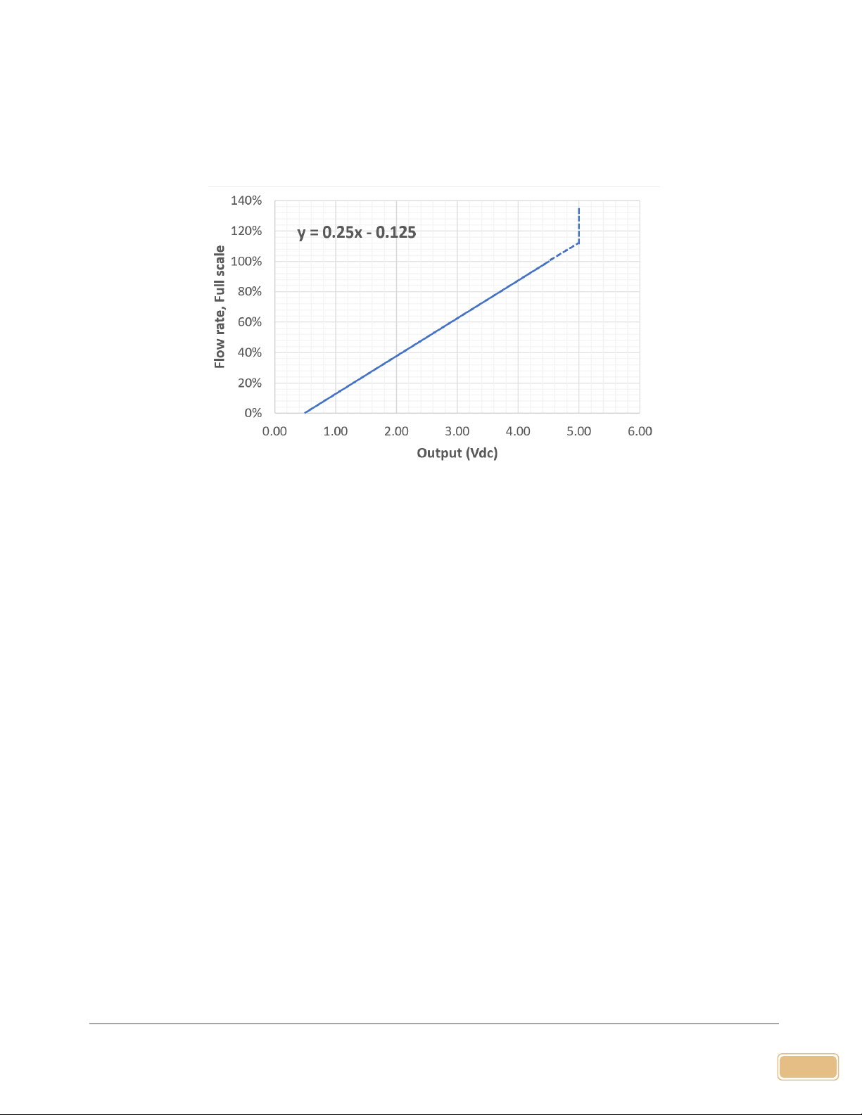
7.2. Analog output
Figure 7.2.1. Typical analog output.

16
www.Siargo.com FS4001 User Manual
8. Technical notes for the product performance
8.1. Measurement principles
The products utilize the Company’s proprietary micro-machined
(MEMS) calorimetric sensing and data process technology. A thermal
signal generator with a pair of sensing elements at the up and
downstream of the microheater is precisely manufactured and
separated at predefined micrometer distances on a chip surface with
excellent thermal isolation. When a fluid is flowing through the sensing
chip, the fluid carries the thermal signal downstream. The sensing
elements register the temperature differences, further correlated to
the fluid mass flow rate via the calibration process.
The calorimetric sensing approach offers a large dynamic range with a
better performance against the environmental parameter alternations.
Please refer to the company's US patents and other publications made available to the public for
additional information.
8.2. Precautions for the best performance of the product
8.2.1. Altitude changes
Unlike some other products on market, the design of the sensor has a built-in pressure balancer that
preventing membrane deformation due to altitude changes. Therefore, the sensor is intrinsically
insensitive to the altitude change-induced errors. The specified altitude in Sec 7.1 has been fully
tested.
8.2.2. Excessive humidity or condensation
The humidity change will not alter the performance of the sensor. However, if excessive humidity is
present resulting in condensation, the measurement port or channel could be blocked or altered.
This would result in a very unreliable data output. Please filter or other tools to prevent this situation
to occur when using this product.
Figure 8.1. Measurement
approach illustration.

17
www.Siargo.com FS4001 User Manual
8.2.3. Metrology verification
Testing the products with local metrology tools will be performed in almost all cases. It should be
noted that for this particular sensor, special care should be applied while performing such a task.
The gauge pressure tests are relatively simple, as long as the pressure is tested under a stable media
condition, the metrology data should be well reproduced.
For the mass flowrate comparison, however, in addition to the flow system setup conditions
recommended by OIML R137, a stable flow system must be ensured. This is because the current
product is designed for a small pressure loss, therefore the sensor does not have a strong flow
restrictor or conditioners to handle the flow instability that may exist in the system. Therefore to
compare the metrology data, the user should ensure the system is stable, otherwise, the output
could be noisy and metrology deviations would be inevitable. If such cases are present, please
contact the manufacturer for further solutions.
For temperature and humidity measurement, because of the small package space, the response of
the humidity could be slower than the specified. For additional information, please contact the
manufacturer.

18
www.Siargo.com FS4001 User Manual
9. Warranty and Liability
(Effective January 2018)
Siargo warrants the products sold hereunder, properly used, and properly installed under normal
circumstances and service. As described in this user manual, it shall be free from faulty materials or
workmanship for 180 days for OEM products and 365 days for non-OEM products from the date of
shipment. This warranty period is inclusive of any statutory warranty. Any repair or replacement
serviced product shall bear the same terms in this warranty.
Siargo makes no warranty, representation, or guarantee and shall not assume any liability regarding
the suitability of the products described in this manual for any purposes that are not specified in this
manual. The users shall be held for full responsibility for validating the performance and suitability
of the products for their particular design and applications. For any of the misusage of the products
out of the scope described herein, the user shall indemnify and hold Siargo and its officers,
employees, subsidiaries, affiliates, and sales channels harmless against all claims, costs, damages,
and expense or reasonable attorney fee from direct or indirect sources.
Siargo makes no other warranty, express or implied, and assumes no liability for any special or
incidental damage or charges, including but not limited to any damages or charges due to installation,
dismantling, reinstallation, etc. other consequential or indirect damages of any kind. To the extent
permitted by law, the exclusive remedy of the user or purchaser, and the limit of Siargo's liability for
any and all losses, injuries, or damages concerning the products, including claims based on contract,
negligence, tort, strict liability, or otherwise shall be the return of products to Siargo, and upon
verification of Siargo to prove to be defective, at its sole option, to refund, repair or replacement of
the products. Regardless of form, no action may be brought against Siargo more than 365 days after
a cause of action has accrued. The products returned under warranty to Siargo shall be at the user or
purchaser's risk of loss and will be returned, if at all, at Siargo's risk of loss. Purchasers or users are
deemed to have accepted this limitation of warranty and liability, which contains the complete and
exclusive limited warranty of Siargo. It shall not be amended, modified, or its terms waived except
by Siargo's sole action.
This manual's product information is believed to be accurate and reliable at the time of release or
made available to the users. However, Siargo shall assume no responsibility for any inaccuracies
and/or errors and reserves the right to make changes without further notice for the relevant
information herein.
This warranty is subject to the following exclusions:
(1) Products that have been altered, modified, or have been subject to unusual physical or
electrical circumstances indicated but not limited to those stated in this document or any
other actions which cannot be deemed as proper use of the products;

19
www.Siargo.com FS4001 User Manual
(2) Products that have been subject to chemical attacks, including exposure to corrosive
substances or contaminants. In the case of battery usage, long term discharge or leakage
induced damages;
(3) Products that have been opened or dismantled for whatever reasons;
(4) Products that have been subject to working conditions beyond the technical specification as
described by this manual or related datasheet published by the manufacturer;
(5) Any damages incurred by the incorrect usage of the products;
(6) Siargo does not provide any warranty on finished goods manufactured by others. Only the
original manufacturer's warranty applies;
(7) Products that are re-sold by unauthorized dealers or any third parties.

20
www.Siargo.com FS4001 User Manual
10. Service contact and information
Siargo Ltd. is making every effort to ensure the quality of the products. In case of questions and or
product supports, please contact customer service at the address listed below. We will respond to
your request in a timely fashion and work with you toward your complete satisfaction.
Customer service and all orders should be addressed to
Siargo Ltd.
3100 De La Cruz Boulevard, Suite 210,
Santa Clara, California 95054, USA
Phone: +01(408)969-0368
For orders, please provide an accurate and full postal address. Siargo will not ship to P.O. Boxes or
via a third party.
the product back to the factory for returns or factory services such as calibration. Please specify as
clear and detailed as possible in your email message the product's status that you intend to ship back
to the factory. Be sure to write the RMA on the returned package or include a letter with the RMA
information.
For further information and updates, please visit www.Siargo.com.
Table of contents
Other Siargo Accessories manuals


Popular Accessories manuals by other brands


IFM Electronic
IFM Electronic efector 250 O2D2 Series Programming manual

weinor
weinor Semina Life Instructions for assembly

Sper scientific
Sper scientific 330001 instruction manual

Moleskine
Moleskine PenPlus Ellipse NWP-F70 user manual

Graco
Graco QUANTM 25F108 instructions

Greenlee
Greenlee 855 Service bulletin

Gemini
Gemini 7709 Installation and maintenance manual

Markilux
Markilux Syncra uno Mounting instructions

Ezviz
Ezviz CS-DB2C quick start guide

Behringer
Behringer Foot Controller FCV100 quick start guide

BEA
BEA CRYSTAL INSTRUCTION MANUAL FOR INDUSTRIAL APPLICATIONS

Frigidaire
Frigidaire GLMB186C installation instructions