Sices ATS LOGICA User manual

Filename: Use and Maintenance
Manual
Rev. 01 Date: 01/03/2016
Product: ATS LOGICA Control Panel
Model with ATS115

2
Use and Maintenance Manual ATS LOGICA CONTROL PANEL with ATS115
THIS MANUAL IS TO BE CONSIDERED AN ATTACHMENT OF THE ATS115
CONTROLLER.
INDEX
1. Introduction to the manual (see also ATS115 manual)...............................................3
2. General conditions of use (see also ATS115 manual)................................................4
3. Installation Instructions (see also ATS115 manual) ...................................................5
3.1 Safety distances.......................................................................................................6
3.2 Control Panel protection...........................................................................................6
4. Start-up...........................................................................................................................7
4.1 Operating logic (standard version)............................................................................7
4.2 Operating DC voltage modification (HW)..................................................................8
4.3 Operating AC voltage modification (HW) (see also attached document)..................8
4.4 Operating AC voltage modification and SW operation (see also attached
document) ....................................................................................................................12
4.5 Operating Logic (standard version) ........................................................................16
4.5.1 Switch carried out by interlocked contactors...................................................16
4.5.2 Switch carried out by motorized changeover switch .......................................17
4.5.3 Power cables interconnections and how to tighten the screws.......................20
4.5.4 AUTO Operating mode...................................................................................22
4.5.5 MANUAL Operating mode..............................................................................23
4.5.6 Position 0 (OFF) .............................................................................................23
5. Composition of the Panel............................................................................................24
5.1 Connection interface terminal board (Switch and Auxiliaries).................................28
6. Options available and possible configurations of the controller ............................31
6.1 Battery Charger SW 5A 12Vdc or 24Vdc (see also related datasheet) ..................31
6.2 Management of two Gensets switching..................................................................32
Option kit diodes bridge D1 .....................................................................................32
Option kit relay KA...................................................................................................33
6.3 Communication ports: RS232, ETHERNET, RS485 (only with ATS115Plus) ........33
6.4 Inhibition.................................................................................................................33
6.5 CTs.........................................................................................................................34
7. Check and maintenance (see also ATS115 manual).................................................35
8. Transport, storage and decommissioning ................................................................36
9. Faults and possible causes (see also ATS115 manual) ...........................................37
10. How to ask for assistance.........................................................................................39
11. Our range: overall dimensions.................................................................................40

3
Use and Maintenance Manual ATS LOGICA CONTROL PANEL with ATS115
SICES is pleased to thank you for purchasing our ATS LOGICA Automatic Transfer Switch Panel.
This Control Panel is the result of the design, the selection of the best components, the careful
assembly and the strict test to which all SICES products are submitted.
We would like to recommend to read this manual carefully, to observe the safety rules and all
regulations for the correct use and maintenance of the ATS LOGICA Control Panel. This will
guarantee you better duration results and efficiency.
For any doubts or questions, please do not hesitate to contact our technicians for clarifications.
The information contained in this manual are updated to the printing stage, but they may still be
modified without notice in compliance with our aims of continuous development and improving of
products.
This manual and all the enclosed documents are to be intended as part of the Control Panel and are
intended to be read by all persons are involved in the life cycle of the machinery. Therefore they
must be collected in a well-known place and be accessible to the operators, keeping them carefully
in order to avoid their loss and/or deterioration.
This manual has been drafted for the installer, the user and the maintenance technician. It is
compulsory to read it carefully and examine all electrical diagrams and instructions enclosed, as they
provide indications on the Control Panel use and they also show the technical characteristics as well
as the installation and assembling features.
The Customer must complies with all the safety instructions.
WARNING:
The automatic transfer switch control panel must be only used by properly
trained personnel.
The installation must only be planned and carried out by skilled personnel.
Any fault in installation and use may cause serious damage to the machinery,
to the user system and to the persons involved.
Please note that it is compulsory to observe all regulations in force in the country of
installation. In case of more regulations in force on the same matter, always consider
the strictest ones.
WARNING:
400V –50 Hz.

4
Use and Maintenance Manual ATS LOGICA CONTROL PANEL with ATS115
The product has been designed and manufactured in compliance with the safety regulations in force,
for use in normal and not classified environments. In order to prevent damages/injuries to things and
persons, we strictly recommend to use all necessary cautions and observe the regulations.
The control panel sizes for the calculation of the dissipated thermal power have been estimated
considering that no other heating sources occur nearby. If the control panel is placed into a room
together with other panels, a suitable distance must be guaranteed in order to allow the dissipation
of the heating produced.
The calculation has been carried out for a use at an average environmental temperature of 35°C,
according to the rules CEI EN 60439-1/2.
In case of need of use at a different environmental temperature, please contact our
technical department for the proper evaluations.
The Control Panel is intended to be used only to the purpose for which it has been designed. Any
other use is considered improper and therefore dangerous.

5
Use and Maintenance Manual ATS LOGICA CONTROL PANEL with ATS115
Do not carry out or try to perform the start-up, maintenance, reparation or modification
you have neither the competence nor the particular instructions.
If any doubt persists after reading the following paragraphs and attachments, please
do not hesitate to contact the SICES Technical Service. All operations must be always
performed in compliance with the safety regulations.
We recommend to check that the Control Panel is intact after unpacking. In case of any doubts, do
not use it, but refer to the manufacturer under penalty of nullity of the warranty.
Before proceeding to the installation, ensure you checked and observed the following indications:
- All installation operations must be performed by skilled personnel who strictly observe the
safety regulations in force in the country where the installation takes place;
- Ensure that the data on the label identifying the control panel comply with the plant values;
in detail, check power, voltage, current and frequency;
- For the electric connection strictly follow the enclosed electric diagram (it contains useful
information);
- In the connection of power and command lines we recommend you to guarantee at least the
section value suggested;
- Ensure that the connection of the earthing protection conductor is always connected
compatibly with the distribution system and the regulations in force in the country of use;
- Ensure that the conductors of the auxiliary circuit are correctly connected. Also check
the correct connection of phase and neutral conductors.
A wrong or missed neutral conductor connection may cause serious damages
to the Control Panel and to the distribution plants connected to it.
Install the Control Panel according to the protection degree. We recommend you to use a cable
gland with the same characteristics in order to avoid a decreasing of the protection value.
The Control Panels must be installed properly. Any faults, modifications to the original project or
interference caused by external agents such as plants, animals, dust, mould, etc. must be removed
or refreshed to the default values.
6
Use and Maintenance Manual ATS LOGICA CONTROL PANEL with ATS115
The panel must be placed at a safe distance from heating sources, fuel storage,
flammable material (paper, cloth, etc.) and chemical substances. The precautions
adopted must be those approved by the competent authorities. In order to avoid
potentially dangerous situations, isolate the area around the panel preventing
unauthorised personnel from approaching.
Although SICES products comply with the electromagnetic compatibility rules,
still we strongly recommend NOT to install the Panel (and the Genset) next to
equipment ejecting emissions.
Pay special attention while assembling the Control Panel in order to prevent external elements from
falling into the Panel, such as metal shavings or other which could damage or impede the operation
of the electric components.
Note
It is the installer’s responsibility to provide a DECLARATION OF CONFORMITY on the Control
Panel installation once the work has been completed.
WARNING: A wrong installation or electrical connection may cause serious
damage to people, Genset, ATS Control Panel and/or plant connected to it.
In order to protect the panel from indirect contact, overload and short-circuit, it is the installer’s
responsibility to connect a protection device on Source A (MAINS) and B (GENSET) with the correct
characteristics and values for the installation point.
In order to guarantee against electrodynamic stress caused by a short circuit for control panels fixed
to the floor, it is necessary to fix the lines to each other or to a support. It is also necessary to provide
supports for the power cables so that these do not weigh down the transfer switch connection bars.
It is the installer’s responsibility to check that the electrical loads connected to the load and the
related current values do not exceed the panel projected value.
The installer must provide the installation of all the necessary equipment aimed at
guarantee a safe and correct operation of the system in which the ATS LOGICA
Control Panel and Genset are installed (e.g. coordination of the protections against
direct and indirect contacts).
Notes: We recommend you to use the suitable equipment (overvoltage protectors) in order to protect
the circuits directly supplied by the Mains from overvoltage due to atmospheric discharges or
particular events.

7
Use and Maintenance Manual ATS LOGICA CONTROL PANEL with ATS115
WARNING:
Every control panel is produced and configured for operations at: 400V –50
Hz.
Control panels between 45 and 125A have the following voltage and frequency values:
DC voltage:
12Vdc.
AC voltage:
400Vac.
(The ABB contactors coils can work at 100÷250V.)
Frequency:
1) 50Hz.
2) 60Hz.
It is possible change the frequency values by modifying a parameter on the ATS115 controller (SW).
Control panels between 160 and 4000A have the following voltage and frequency values:
DC voltage switch.
The Control Panels are suitable for operating at different genset battery voltages:
1) 12Vdc.
2) 24Vdc.
It is possible change this level by modifying the Hardware on the control panel internal wiring (see
par. 4.2).
AC voltage switch.
The Control Panels are suitable for operating at different AC voltages:
3) 220Vac.
4) 380Vac.
5) 400Vac.
6) 440Vac.
In order to adjustthe Control Panel to the different AC voltage level, it is necessary to carry outsome
operations related to both control panel internal connections (HW) and ATS115 controller
parameters modifications (SW).

8
Use and Maintenance Manual ATS LOGICA CONTROL PANEL with ATS115
Frequency:
1) 50Hz.
2) 60Hz.
It is possible change the frequency values by modifying a parameter on the ATS115 controller (SW).
In order to change the DC voltage, connect the 2.7B wire (identified by red rings) to the RB
wire clamp:
1) Battery Voltage 12Vdc: wire 2.7B to wire clamp 12
2) Battery Voltage 24Vdc: wire 2.7B to wire clamp 24.
(Example of 24Vdc operation)
For the HW change, see the attached document in the documentation supplied with the
control panel and reported below.
WARNING: All voltage switch operations have to be
carried out before the operation start, with absence of
voltage.
THE CONTROL PANEL IS PRODUCED AND CONFIGURED FOR THREE-PHASE + NEUTRAL
400V OPERATIONS.

9
Use and Maintenance Manual ATS LOGICA CONTROL PANEL with ATS115
WARNING:
The cables in the figures below have a numeration that may not correspond to the control panel in
use.
They only have a demonstrative purpose. See the electrical diagram to identify the right cable
number to take in consideration in order to modify the operating voltage.
The sticker on the control panel rear door identifies the internal equipment.
BEFORE CHANGING THE VOLTAGE:
Disconnect the supply of the following devices: “KBG” (capacity 160÷4000A), “KR-KG” (capacity
45÷125A), power supply “A2” (optional).
“KBG” “KR-KG” “A2” (optional)
For the voltage change (size 45÷125A) please contact SICES Sales Department.
Remove the protection panel and disconnect the
changeover switch connector.
KBG = ABB KBG = TECHNOELECTRIC
(Lower side) (Upper side)
Disconnect the coil
supply connector.

10
Use and Maintenance Manual ATS LOGICA CONTROL PANEL with ATS115
The VOLTAGE SWITCH is carried out in the “X1” bar and in the “TR1” autotransformer for
160÷4000A capacities.
X1 TR1
On “X1” bar and on “TR1” the connected cables are
identified by 3 red rings.
ENSURE THAT THE CABLES WITH THE RED RINGS ARE PLACED AS REPORTED IN THE
ELECTRICAL DIAGRAM SPECIFICATIONS.
ENSURE THAT THE CABLES WITH THE RED RINGS ARE PLACED AS REPORTED BELOW
AND SEE THE ELECTRICAL DIAGRAM SPECIFICATIONS FOR THE IDENTIFICATION OF THE
NUMBER OF CABLES.
OPERATING VOLTAGE: 220V (MOVE THE RED RINGED CABLE ONLY)
-X1--TR1-
220V 220V
Right
Left
Side by side
NOTE: for the side by side “X1” bar, the red ringed cable is connected to the terminals with an “odd
number” (left).
WARNING: it is advisable to move one cable at a time in order to avoid inverting the sequence with
the other cables.
CHECK THE VOLTAGE ON THE SWITCH AND POWER SUPPLY CONNECTORS (OPTIONAL).
11
Use and Maintenance Manual ATS LOGICA CONTROL PANEL with ATS115
After the control panel is configured with the correct voltage value, supply the “XR” and “XG” bar with
the operating voltage in order to check.
The voltage on the “XM-1” and “XM-2” bar and on the “”KBG” switch supply connector (ABB), or
with “KR” and “KG” must be 230V.
Disconnect the voltage and put the supply connectors again at their place:
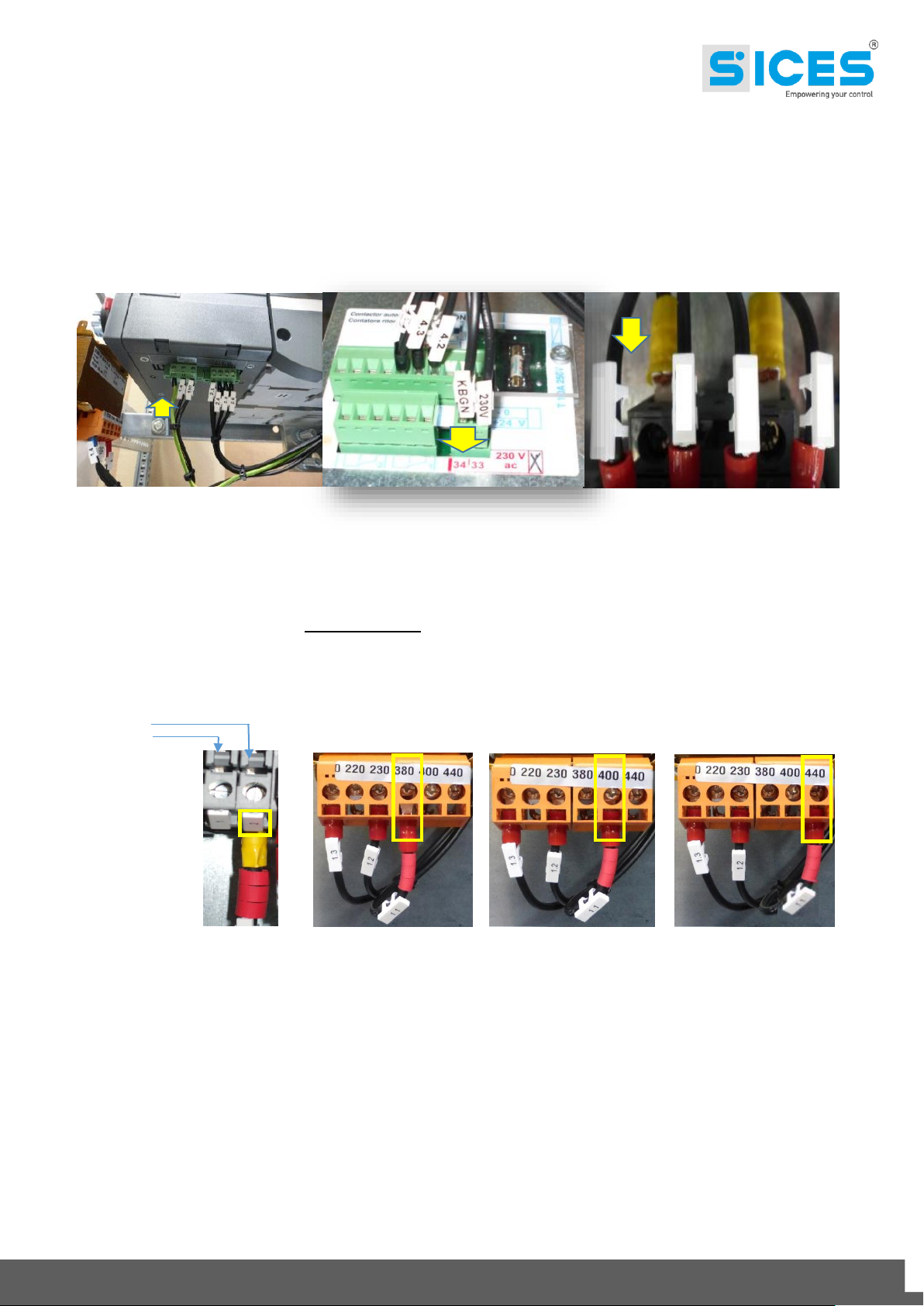
OPERATING VOLTAGE: 380/400/440V (move the red ringed cable only)
-X1- -TR1- -TR1- -TR1-
380/400/440V 380V 400V 440V
Right
Left
Side by side
NOTE: for the side by side “X1” bar, the red ringed cable is connected to the terminals with an “even
number” (right).
WARNING: it is advisable to move one cable at a time in order to avoid inverting the sequence with
the other cables.
“KR-KG”
“KBG”
ABB
“KBG”
TECHNOELECTRIC
12
Use and Maintenance Manual ATS LOGICA CONTROL PANEL with ATS115
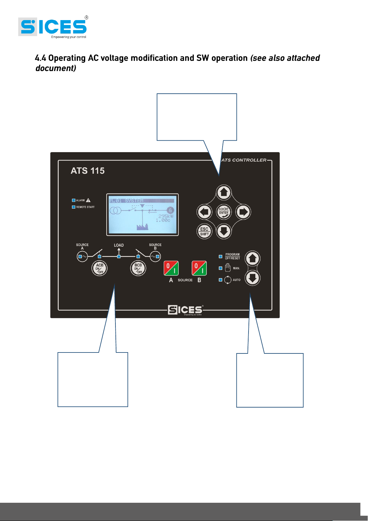
OFF / AUTO / MAN Set the parameters by means of the configuration keyboard.
Arrow keys for the
navigation and
CONFIGURATION
Area
Buttons for the
modes
Arrow keys for the
modes
OFF/AUTO/MAN

13
Use and Maintenance Manual ATS LOGICA CONTROL PANEL with ATS115
OFF/AUTO/MAN Area
Using the arrow keys put the device on
CONFIGURATION Area
Using the arrow keys select the page 03 PROGRAM
+
Using the arrow keys select the submenu: 1 System
+
14
Use and Maintenance Manual ATS LOGICA CONTROL PANEL with ATS115
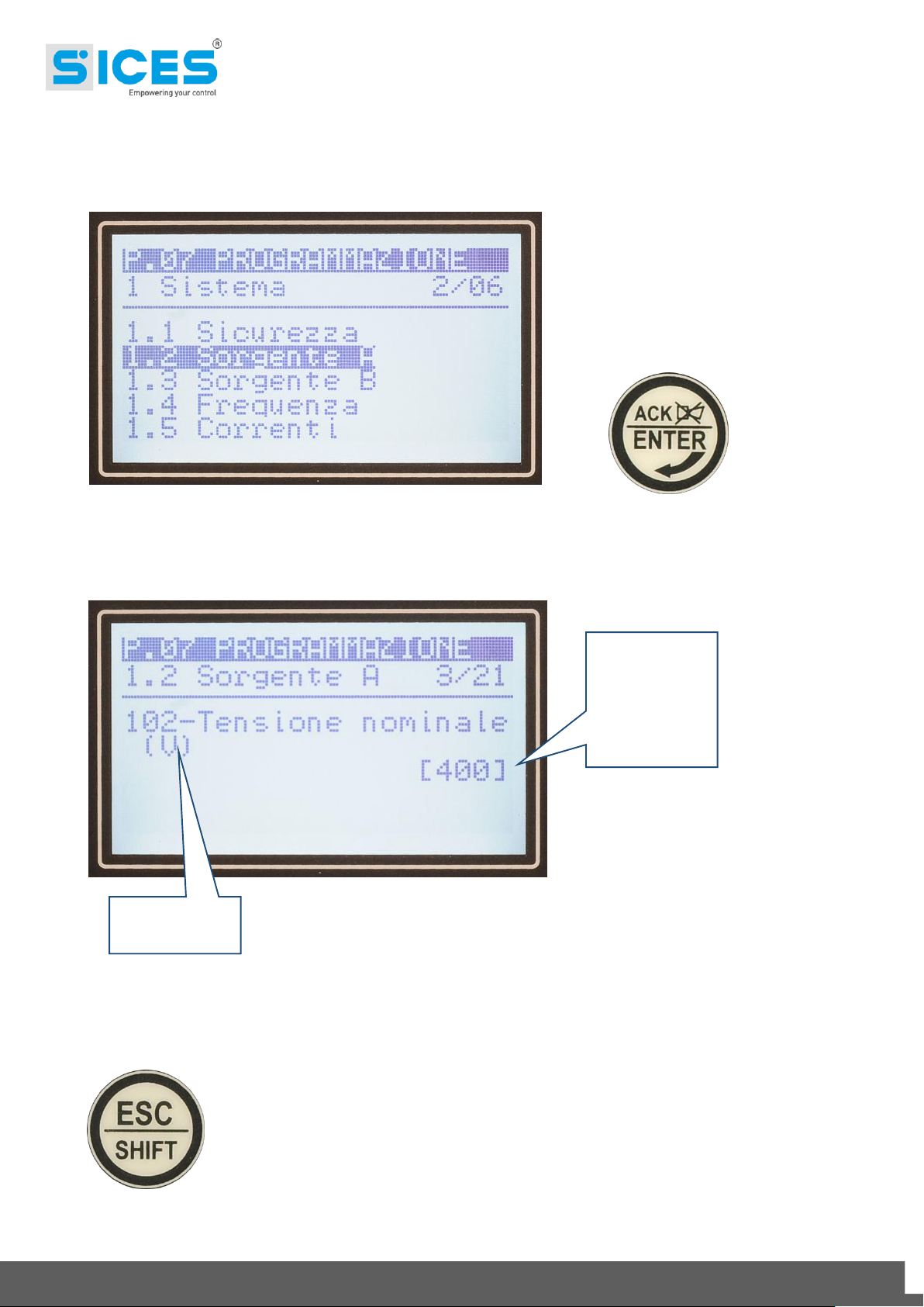
Using the arrow keys select the submenu: 1.2 - Source A (see the example)
1.3 - Source B
+
Using the arrow keys and scroll the parameters indicated (the example indicates the parameter
P.0102)
The square brackets [ ] flash to indicate that the value can be changed.
Using the arrow keys define the new value and confirm with ENTER (the square brackets stop
flashing).
Press ESC in order to go back to the main menu and to browse through pages.
The parameters that must be changed for the voltage modification are all listed in
the submenu 1-System.
Value to
define
Parameter
number

15
Use and Maintenance Manual ATS LOGICA CONTROL PANEL with ATS115
Find below the new values to define (see the ATS115 manual in order to change the parameters by
the controller keyboard).
1) Operating voltage 220V
a. P.0102 = 220
b. P.0202 = 220
2) Operating voltage 380V
a. P.0102 = 380
b. P.0202 = 380
3) Operating voltage 400V:
a. P.0102 = 400
b. P.0202 = 400
4) Operating voltage 440V:
a. P.0102 = 440
b. P.0202 = 440
5) Nominal frequency 50Hz:
a. P.0301 = 50
6) Nominal frequency 60Hz:
a. P.0301 = 60
16
Use and Maintenance Manual ATS LOGICA CONTROL PANEL with ATS115
The ATS LOGICA Control Panel is a device that allows to supply alternatively a system that uses
two different and independent sourcesof energy,which usually are:Source A (Mains) and/or Source
B (Genset).
According to the nominal current, besides the panel circuits, the switch takes place by means of:
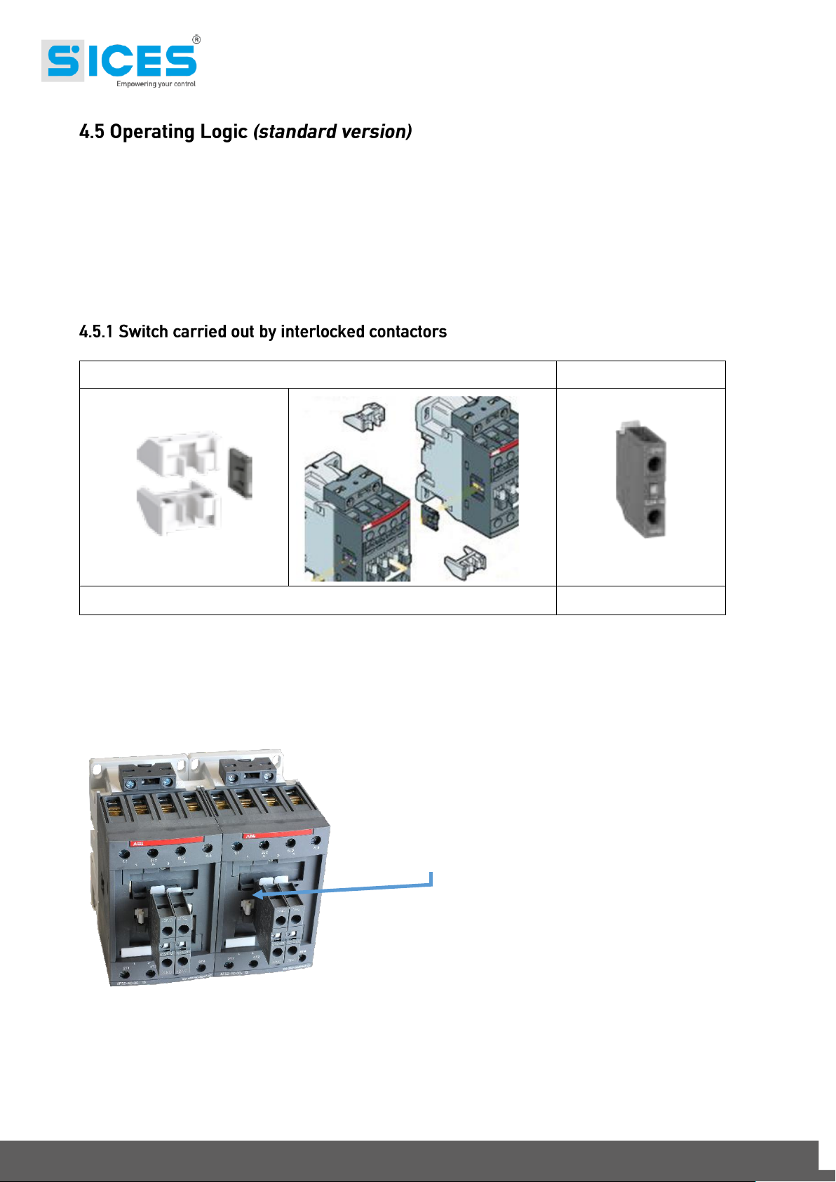
1) 2 four-pole contactors which are electrically and mechanically interlocked (45 - 125A);
2) 1 motorized four-pole changeover switch (160 –4000A).
Mechanical interlock
Auxiliary contacts
45÷125A
45÷125A
The contactors are interlocked by means of a proper accessory. In order to guarantee more safety
to the system, besides the mechanical interlock, there is an electrical interlock carriedout by auxiliary
contacts installed on the front of each contactor.
With this configuration, only one of the two contactors
can be commanded; the second one stays deactivated.
In this way, the load is always supplied by only one source.
When the contactor is closed, the mechanical part in the
figure stays blocked.

17
Use and Maintenance Manual ATS LOGICA CONTROL PANEL with ATS115
The standard version considers the use of the following materials:
From 160A to 2500A: Motorized changeover switch ABB SACE
From 3150 to 4000A: Motorized changeover switch TECHNOELECTRIC
On the front of the motorized changeover switch (160÷4000A) there is a mechanical indicator that
shows the status of the main contacts. Therefore, it is possible to understand on which source the
load is inserted. The figure below shows the possible statuses:
ABB SACE
Source A
Source B
Source A
Source B
Source A
Source B
WITH INDICATOR ON “0”
(ZERO) THE LOAD IS NOT
SUPPLIED BY ANY SOURCE
WITH INDICATOR ON “I”
(ONE) THE LOAD IS SUPPLIED
BY THE GENSET
WITH INDICATOR ON “II”
(TWO) THE LOAD IS
SUPPLIED BY THE MAINS

18
Use and Maintenance Manual ATS LOGICA CONTROL PANEL with ATS115
TECHNOELECTRIC
WARNING: Check the cyclic sense of the Source A (MAINS) and the Source B
(GENSET) phases before supplying the LOAD.
The inverse cyclic sense can cause serious damages to the system.
Source A
Source B
Source A
Source B
Source A
Source B
WITH INDICATOR ON “0”
(ZERO) THE LOAD IS NOT
SUPPLIED BY ANY SOURCE
WITH INDICATOR ON “I”
(ONE) THE LOAD IS SUPPLIED
BY THE GENSET
WITH INDICATOR ON “II”
(TWO) THE LOAD IS
SUPPLIED BY THE MAINS

19
Use and Maintenance Manual ATS LOGICA CONTROL PANEL with ATS115
On the front of the switch there is a series of accessories:
1 A lock that impedes any manual or electrical operation.
2 Mechanical indicator of the circuit breakers status.
3 Command selector switch: manual/automatic.
The locking device is important in case you would like to impede any operation by unauthorized
persons, or to guarantee that nobody modifies the supply status creating damage to the people
working in the plant. By means of the locking system placed on the front, you impede the activation
of the manual command. With lock inserted the supply is stopped, inhibiting the electrical command.
The changeover switch, thanks to its exclusive mechanical structure, can be activated manually by
a proper lever. This operation can be useful in case of device failure or in case of connection failure
to the remote control logic.
2
2
2
1
ABB
FRONT VIEW
WARNING
In order to manage the changeover
switch manually, disconnect the
electrical command by removing the
supply connector. Then activate the
command lever.
OTHERWISE, THE DEVICE CAN BE
DAMAGED.
3
1
2
TECHNOELECTRIC
FRONT VIEW
WARNING
In order to manage the changeover
switch manually, disconnect the
electrical command by removing the
supply connector. Then activate the
command lever.
OTHERWISE, THE DEVICE CAN BE
DAMAGED.
20
Use and Maintenance Manual ATS LOGICA CONTROL PANEL with ATS115
In order to make the changeover switch close one of the two sources and supply the load, the ATS
LOCIGA control panel must be always connected to receive the values of the SOURCE A (MAINS)
and SOURCE B (GENSET) voltage, keeping the ATS115 controller on AUTO.
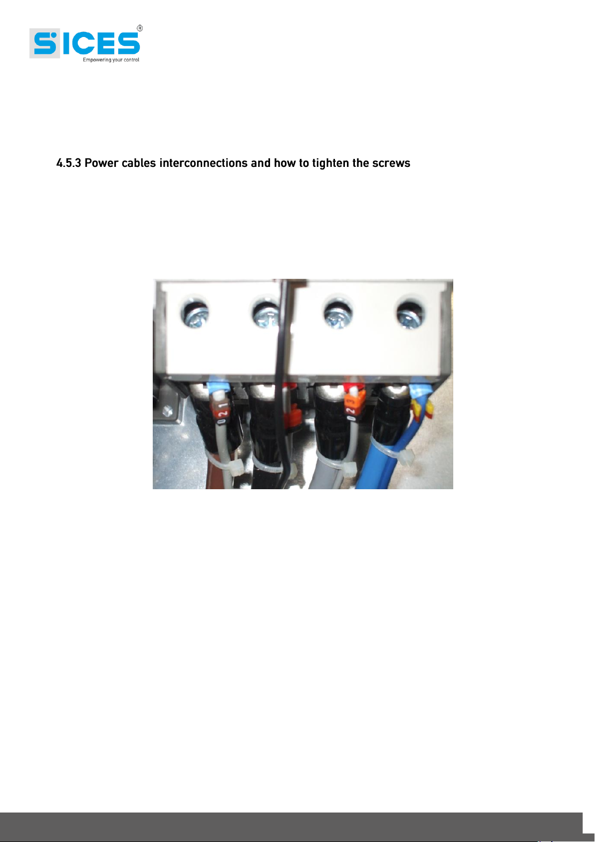
When the connection of the power cables Source A (MAINS) - Source B (GENSET) is carried out
directly on the contactors terminals (sizes 45÷125A), the operation brings to the disconnection of the
auxiliary circuits cables connected to the terminals. Pay attention during the reconnection of the
auxiliarycircuits cables to the power cables in theterminals. Before supplying, ensure that they have
been reconnected correctly according to the diagram.
A wrong connection can cause damage to the auxiliary circuits inside the electrical control panel.
This manual suits for next models
1
Table of contents
Other Sices Control Panel manuals


