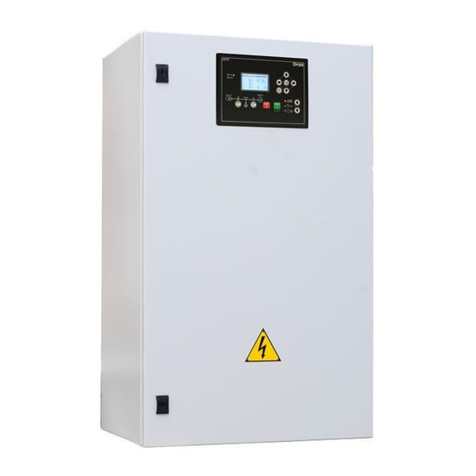
Sices GC310 User manual

Filename: Use and maintenance manual
Rev. 00 Date: 23/09/2014
Product: AUTOMATIC GENSET
CONTROL PANEL with GC310/GC350

2
Use and maintenance Manual AUTOMATIC GENSET CONTROL PANEL with GC310/GC350
THIS MANUAL IS TO BE CONSIDERED AN ATTACHMENT OF THE GC310/GC350
CONTROLLER MANUAL.
INDEX
1. Introduction to the manual (see also GC310/GC350 manual)....................................3
2. General conditions of use (see also GC310/GC350 manual) .....................................4
3. Instructions for the installation (see also GC310/GC350 manual).............................5
3.1 Safety distances.......................................................................................................6
3.2 Control panel protection ...........................................................................................6
3.3 Power cables connection and screw tightening: switchover.....................................7
3.4 Power cables connection and screw tightening: genset protection switch................8
4. Start-up (see also GC310/GC350 manual) ...................................................................9
4.1 General information..................................................................................................9
4.2 Additional services....................................................................................................9
4.2.1 External emergency stop..................................................................................9
4.2.2 Battery charger.................................................................................................9
4.2.3 Engine pre-heating ...........................................................................................9
4.3 Working logic (standard version)............................................................................10
4.3.1 Changeover carried out by couple of contactors.............................................10
4.3.2 Changeover carried out by motorized switch..................................................11
4.3.3 Automatic mode..............................................................................................13
4.3.4 Manual mode..................................................................................................14
4.3.5 Test mode.......................................................................................................15
5. Control panel composition .........................................................................................16
5.1 Connection terminal board interface (power and auxiliaries)..................................21
6. Check and maintenance (see also GC310/GC350 manual) ......................................25
7. Transport, storage, decommissioning.......................................................................26
8. Faults and possible causes (see also GC310/GC350 manual).................................27
9. How to ask for assistance...........................................................................................29
10. Overall dimensions....................................................................................................30
11. Slot dimensions and assembly ................................................................................31

3
Use and maintenance Manual AUTOMATIC GENSET CONTROL PANEL with GC310/GC350
SICES is pleased to thank you for purchasing our Automatic Genset Control Panel.
These Control Panels are the result of the design, the selection of the best components, the careful
assembly and the strict tests to which all SICES products are submitted.
We recommend to read this manual carefully and to observe the safety rules and all regulations for
the correct use andmaintenance of the Control Panel. This will guarantee better duration results and
efficiency.
In case of any doubts or questions, please do not hesitate to contact SICES technicians for
clarifications.
The information contained in this Manual are updated to the printing stage, but they may be modified
without notice in compliance with our aims of continuous development andimprovement of products.
This manual and all enclosed documents are to be intended as part of the Control Panel and are
intended to be read by all those who are involved in the life cycle of the machinery; therefore they
must be collected in a well-known place and be accessible to the operators, keeping them carefully
in order to avoid their loss or deterioration.
This manual has been drafted for the installer, the user and the maintenance technician. It is
obligatory to read it carefully and view all electrical diagrams and instructions enclosed, as they
provide indications on the Control Panel use and also show the technical characteristics, as well as
the installation and assembling features.
The customer must observe all safety instructions.
WARNING:
The transfer switch control panel must be only used by properly trained
personnel.
The installation must only be planned and carried out by skilled personnel.
Any fault in installation and use may cause serious damage to the machinery,
to the user system and to the persons involved.
Please note that it is obligatory to observe the regulations in force in the Country where
the installation is carried out; in case of more than one regulation in force around the
same topic, always the strictest one must apply.

4
Use and maintenance Manual AUTOMATIC GENSET CONTROL PANEL with GC310/GC350
The product has been designed and manufactured in compliance with the safety regulations in force,
for use in normal and not classified environments.
In order to prevent damages and injuries to things and persons, we strictly recommend to use all
necessary caution and observe the regulations.
The Control Panel dimensions for the calculation of the wasting heat power have been estimated
considering that no other heating sources occur nearby.
If the Control Panel is placed into a room together with other panels, a suitable distance allowing the
wasting of the heating produced must be guaranteed.
The calculation has been carried out for a use at 35°C average environmental temperature
according to CEI EN 60439-1 and IEC 439-1rules.
In case it is necessary to use the equipment at a different average ambient
temperature, please contact our Engineer Department for the necessary evaluations.
The Control Panel must only be intended for the purpose to which it has been designed. Any other
use is considered improper and therefore dangerous.

5
Use and maintenance Manual AUTOMATIC GENSET CONTROL PANEL with GC310/GC350
Do not carry out or try to perform actions of start-up, maintenance, reparation or
modification you have neither the specific expertise nor the precise instructions.
If any doubt persists after reading the following paragraphs and attachments, please
do not hesitate to contact SICES Technical Service. All actions must always be
performed complying with safety regulations.
We recommend to check that the Control Panel is intact after unpacking. In case of doubts, do not
use it, but refer to the manufacturer under penalty of warranty nullity.
Before proceeding to the installation, ensure you checked and observed the following indications:
- All installation operations must be performed by skilled personnel who strictly observe the
safety regulations in force in the country where the installation takes place;
- Ensure that the data on the identifying label of the control panel comply with the plant values;
in detail, check the power, the voltage, the current and the frequency;
- For the electric connection, strictlyfollow the enclosed electric diagram, which contains useful
information;
- In the connection of the power and command lines, we recommend to guarantee at least the
section value suggested;
- Ensure that the connection of the earthing protection conductor is always connected,
compatibly with the distribution system and the regulations in force in the country of issue;
- Ensure that the conductors of the auxiliary circuit are correctly connected. Also check
the correct connection of the phase and neutral conductors.
A wrong or missed neutral conductor connection may cause serious damages
to the Control Panel and to the distribution plants connected to it.
Install the control panel according to the protection degree.We recommend the use of a cable press
with the same characteristics, in order to avoid a decrease of the protection value.
The control panels must be installed properly. Any faults, modifications to the original project,
interferences from external agents such as plants, animals, dust, mould, etc. must be removed or
restored to the default values.

6
Use and maintenance Manual AUTOMATIC GENSET CONTROL PANEL with GC310/GC350
The panel must be placed at a safe distance from heating sources, fuel storage,
flammable material (paper, cloth, etc.) and chemical substances. The precautions
adopted must be those approved by the competent authorities. In order to avoid
potentially dangerous situations, isolate the area around the panel preventing
unauthorised personnel from approaching.
Although SICES products comply with the electromagnetic compatibility rules,
we still strongly recommend NOT to install the Panel (and Genset) next to
equipment ejecting emissions.
Pay special attention while assembling the control panel, in order to prevent external elements from
falling into the panel, i.e. metal shavings or other which could damage or impede the operation of
the electric components.
CEI EN 60439-1 rule assigns INDIVIDUAL TESTS to the installer, in particular the following points:
- 8.3.1. Equipment inspection, including cable inspection and insulation test;
- 8.3.3. Protection measures check.
Note:
It is responsibility of the installer to provide a DECLARATION OF CONFORMITY around the
Control Panel installation once the work has been completed.
WARNING!
A wrong installation or electrical connection may cause serious damage to
persons, Genset, Control Panel and/or plants connected to it.
In order to protect the panel from indirect contacts, overload and short-circuit, it is the installer
responsibility to connect a protection device on the MAINS line with the correct characteristics and
values for the installation point.
As guarantee against electrodynamics stress caused by a short circuit, for panels fixed to the floor,
it is necessary to fix the various lines to each other or to a support. It is also necessary to provide
supports for the power cables so that these don’t weigh down the transfer switch connection bars.
It is the responsibility of the installer to check that the electrical loads connected to the load and its
relative current values do not exceed the projected value of the panel.
The installer must provide the installation of all the necessary equipment apt to
guarantee a safe and correct operations of the system in which the genset control
panel is installed (i.e. coordination of the protections against direct and indirect
contacts).
Note: We recommend the use of proper devices (overvoltage arresters) in order to protect the
circuits directly supplied by the Mains from overvoltage due to atmospheric discharges or particular
events.

7
Use and maintenance Manual AUTOMATIC GENSET CONTROL PANEL with GC310/GC350
WARNING: Before connecting the phase and neutral conductors of MAINS,
GENSET and LOAD to the control panel, it is the installer responsibility to check
the type of distribution system of the plant.
Pay special attention to check the function of the neutral conductor. If it takes on
the combined neutral and protection function (PEN), IT MUST NOT BE SELECTED.
A wrong or missed neutral conductor connection may cause serious damages to
the Control Panel and to the distribution plants connected to it.
For powers (35÷80kVA), the power cables connection has to be carried out in the terminal board.
For the remaining powers (100÷1580kVA), the power cables connection has to be carried out in the
extension bars.
During the closing phase of the screws that tighten the cable or connection terminals on the bars,
look out not to overtighten the screws, but follow the values of the following table:
SCREW TIGHTENING TORQUE (MAX)
TERMINAL BOARD (35÷80kVA)
MOTORIZED SWITCH (100÷1580kVA)
16mm2
35mm2
CS2
CS3
CS4
CS5
CS6
M5
M6
M8
M10
M12
M16
M14
2 Nm
2.5 Nm
20 Nm
35 Nm
65 Nm
160 Nm
100 Nm

8
Use and maintenance Manual AUTOMATIC GENSET CONTROL PANEL with GC310/GC350
WARNING: Before connecting the phase and neutral conductors of MAINS,
GENSET and LOAD to the control panel, it is the installer responsibility to check
the type of distribution system of the plant.
Pay special attention to check the function of the neutral conductor. If it takes on
the combined neutral and protection function (PEN), IT MUST NOT BE SELECTED.
A wrong or missed neutral conductor connection may cause serious damages to
the Control Panel and to the distribution plants connected to it.
For powers (35÷80kVA), the power cables connection has to be carried out in the terminal board.
For the remaining powers (100÷1580kVA), the power cables connection has to be carried out in the
extension bars.
During the closing phase of the screws that tighten the cable or connection terminals on the bars,
look out not to overtighten the screws, but follow the values of the following table:
SCREW TIGHTENING TORQUE (MAX)
TERMINAL BOARD (35÷80kVA)
ABB AUTOMATIC SWITCH (100÷1580kVA)
16mm2
35mm2
XT2
T5 (200-250kVA)
T5 (300-400kVA)
T7
T8
M8
M10
M12
2 Nm
2.5 Nm
20 Nm
35 Nm
65 Nm

9
Use and maintenance Manual AUTOMATIC GENSET CONTROL PANEL with GC310/GC350
In the following pages there will be described in particular the prescriptions of the control panel and
the sequences the operator shall manage.
Before the automatic start-up of the plant, it is advisable to check the good operation of the genset.
In order to guarantee the correct operation of the plant, there are the following devices included:
In case of need of an external emergency stop button, it is possible to connect it to the terminals
n°1/2 on the terminal board XA, after removing the existing bridge.
The Genset is equipped with its own battery charger alternator for the battery recharge sufficient for
the maintenance of the batteries charge when they are working.
Otherwise, when the Genset is not in operation (with Mains presence), it is necessary to maintain
the batteries in perfect charge (to compensate for the auto-discharge, the consumption of the
auxiliary circuits, etc.) in order to guarantee always a good start-up.
Therefore, the panel is equipped with a proper automatic battery charger supplied by the Load, which
is composed by a mechanic unit made up of the electric machine (transformer) and the electronic
control, which includes a heat sink for the components that modulate the charge and internal status
LEDs.
For further details of the characteristics and the operations of control, see the proper operations
manual.
In order to reach the ideal conditions to allow a rapid genset start-up and load pick-up, the engine
water is kept at a medium temperature of 40/50°C. In the internal water circuit there are electrical
heating resistances, with a thermostat device (thermostat contact that closes with min. engine
temperature) that commands the insertion. The circuit supply is resulted from the mains line,
deactivating it automatically when the genset begins to work (in case of mains failure).

10
Use and maintenance Manual AUTOMATIC GENSET CONTROL PANEL with GC310/GC350
The Genset Automatic Control Panel is a device which allows to manage the load supply from two
separate and independent sources of energy that are: the Mains and the Genset.
According to the nominal current, the switch Mains/Genset is carried oud by means of:
- Up to 125A (35 ÷ 80kVA): 2 4-pole contactors mechanically and electrically interlocked
- From 160A (100 ÷ 1580kVA): 1 4-pole motorized switch TECHNOELECTRIC
MECHANIC INTERLOCK
AUXILIARY CONTACTS
35-53kVA
70-80kVA
35-80kVA
The couple of contactors is mechanically interlocked by
means of the proper device. In order to guarantee a greater
security of the plant, the contactors position is electrically
interlocked by means of auxiliary contacts on the front of the
contactor (see table above).
This system ensures the insertion of one contactor at a time,
in order to avoid to supply the load by both sources
(mains/genset).
When the contactor is excited by the mechanic part, as
shown by the arrow, it comes back.

11
Use and maintenance Manual AUTOMATIC GENSET CONTROL PANEL with GC310/GC350
In the front of the motorized switch (100÷1580kVA) there is a mechanic position indicator that shows
the status of contacts, so the load status in respect to MAINS and GENSET. In the figure below, the
possible status are shown:
TECHNOELECTRIC
WARNING: check the cyclic direction of the phases MAINS and GROUP before
supplying the LOAD.
The reverse cyclic direction can cause serious damages to the machinery.
WITH INDICATOR
IN POSITION “0”
THE LOAD IS NOT
SUPPLIED BY ANY OF THE
TWO SOURCES
WITH INDICATOR
IN POSITION “2”
THE LOAD IS SUPPLIED
BY THE GENSET
WITH INDICATOR
IN POSITION “1”
THE LOAD IS SUPPLIED
BY THE MAINS

12
Use and maintenance Manual AUTOMATIC GENSET CONTROL PANEL with GC310/GC350
In front of the switch there is a series of devices, as:
1 Lock that impedes any electric or manual operation.
2 Mechanic indicator of the contacts status.
3 Bush for the insertion of the handle for the manual operation of the switch.
The motorized switch, thanks to its exclusive device, can be managed manually by a proper lever,
even in case of no connection to the remote control logic or damaged system.
The lock is important in case you would like to impede any operation to unauthorized persons, or in
case you would like to ensure that nobody changes the supply status, causing danger to those who
manage the plant. Using the frontal lock, the insertion of the handle for the manual operation is
impeded. With inserted lock, stopping the supply, the electric operation is inhibited too.
The genset control panel must be connected to receive MAINS and GENSET voltage values,
keeping GC310/GC350 in AUTO mode, so that the switch can close automatically on one of the two
sources and supply the plant.
2
TECHNOELECTRIC
FRONTAL VIEW MODELS
CS 4-5-6
WARNING
For the manual operation of the switch, disconnect the
electric command by removing the supply connector.
Then move the operation lever.
OTHERWISE THE DEVICE CAN BE DAMAGED

13
Use and maintenance Manual AUTOMATIC GENSET CONTROL PANEL with GC310/GC350
All genset control logics are carried out by the GC310/GC350 controller with microprocessor:
Set the GC310/GC350 controller in AUTO mode, using the selection arrows.
The operation cycle is composed as follows:
In case of mains failure or trespassing of the thresholds values set
(calibrations and configurations set in the GC310/GC350 controller)
and with GC310/GC350 in AUTO mode, the genset start-up sequence
begins.

14
Use and maintenance Manual AUTOMATIC GENSET CONTROL PANEL with GC310/GC350
After the genset start-up, the controller GC310/GC350 measures the
genset voltage value.
The controller GC310/GC350 controls the
status switch, from MAINS to GENSET, in
order to supply the load.
When the mains voltage
comes back to the
threshold values set,
GC310/GC350 produces a reverse
sequence to the previous cycle and brings
the system supply back to Mains,
disconnecting the Genset.
Set the GC310/GC350 controller in MAN. mode, using the selection arrows.
Manual start-up control of the Genset
Manual stop control of the Genset
In MAN mode, by pressing this button it is possible to
change the switch position MAINS/GENSET (the
controller must have the start-up control of the genset
and measure the start-up genset voltage).
This operation cycle is managed with times and thresholds settable in the GC310/GC350 controller.
All these values are changeable by the user and can be consulted in the controller manual.
Note: Please remember that with Mains live and GC310/GC350 in OFF mode, the switch is
commanded to close always in MAINS position.

15
Use and maintenance Manual AUTOMATIC GENSET CONTROL PANEL with GC310/GC350
Set the GC310/GC350 controller in TEST mode, using the selection arrows.
It allows the automatic start of the genset for the periodic test, enabling the protections. The switch
Mains/Genset is excluded. Any possible mains failure, with lighting of the LED connected to it,
causes the immediate genset supply.
+
This function is enabled by selecting the AUTO/TEST button and by pressing the START and STOP
buttons together.

16
Use and maintenance Manual AUTOMATIC GENSET CONTROL PANEL with GC310/GC350
STEEL SHEET BOX (35÷53kVA)
Terminal
board
interface
Auxiliaries
zone
Power zone
Power cables
connection -
XR-MAINS
Power cables
connection -
XL-LOAD
Power cables
connection -
XG-GENSET
Earthing bar
Terminal
board
XA
Terminal
board
XM

17
Use and maintenance Manual AUTOMATIC GENSET CONTROL PANEL with GC310/GC350
STEEL SHEET BOX (80kVA)
Terminal
board
interface
Terminal
board
XM
Terminal
board
XA
Power cables
connection -
XR-MAINS
Power cables
connection -
XL-LOAD
Power cables
connection -
XG-GENSET
Earthing bar
Power zone
Auxiliaries
zone

18
Use and maintenance Manual AUTOMATIC GENSET CONTROL PANEL with GC310/GC350
STEEL SHEET BOX (100kVA)
Auxiliaries
zone
Bars
protection
Terminal
board
XA
Interface
cable return
duct
Earthing bar
Power zone
Power cables
connection
bars -
XL-LOAD
(front)
Power cables
connection
bars -
XR-MAINS
(back)
Power cables
connection
bars -
XG-GENSET
Terminal
board
XM

19
Use and maintenance Manual AUTOMATIC GENSET CONTROL PANEL with GC310/GC350
STEEL SHEET BOX (200÷400kVA)
Terminal
board
XA
Interface
cable return
duct
Auxiliaries
zone
Protection
bars
Earthing bar
Power cables
connection
bars -
XG-GENSET
(front)
Power cables
connection
bars -
XR-MAINS
(back)
Power zone
Terminal
board
XM
Power cables
connection
bars -
XL-LOAD

20
Use and maintenance Manual AUTOMATIC GENSET CONTROL PANEL with GC310/GC350
FLOOR STANDING STEEL SHEET CABINET (500÷1580kVA)
Auxiliaries
zone
Interface
cables return
duct
Earthing bar
Power zone
Terminal
board
XM
Power cables
connection
bars -
XL-LOAD
(front)
Power cables
connection
bars -
XR-MAINS
(back)
Power cables
connection
bars -
XG-GENSET
Terminal
board
XA
Interface
cable return
duct
Bars
protection
Other manuals for GC310
1
This manual suits for next models
1
Other Sices Control Panel manuals
