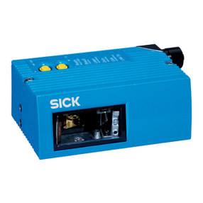
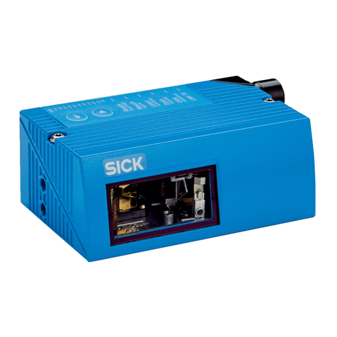
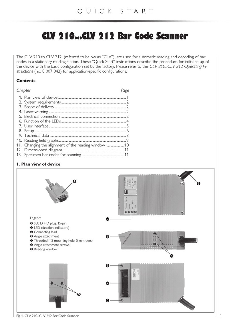
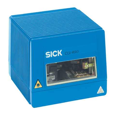
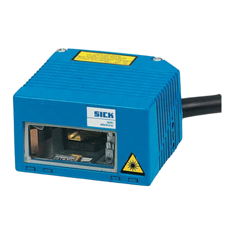
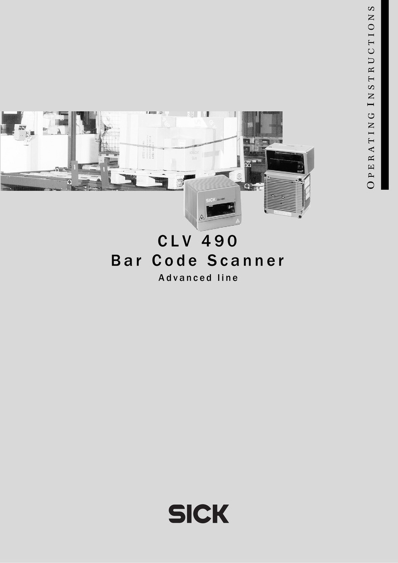
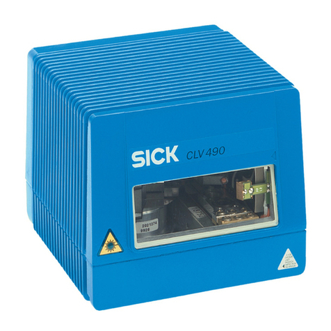
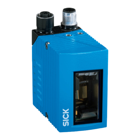
SICK CLV 480 User manual

OPERATING INSTRUCTIONS
CLV 480
Bar Code Scanner
Advanced line

Operating Instructions
CLV 480 Bar Code Scanner
I-2 ©SICK AG · Division Auto Ident · Germany · All rights reserved 8 010 080/O824/10-02-2005
Software versions
Software versions
Copyright
Copyright ©2005
SICK AG Waldkirch
Auto Ident, Reute Plant
Nimburger Strasse 11
79276 Reute
Germany
Trademarks
Windows 95TM/98TM, Windows NTTM, Windows 2000TM, Windows XPTM and Internet
ExplorerTM are registered trademarks or trademarks of the Microsoft Corporation in the USA
and other countries.
Latest manual version
For the latest version of this manual (PDF), see www.sick.com.
Software/Tool Function Version
CLV 480-0010/-0011 Firmware From V 3.5 O824
CLV 480-1010/-1011 Firmware From V 3.5 O824
CLV-Setup User interface (windows-based) From V 4.1 O508
CLV-Setup Help Online help (HTML) From V 4.1 O508

Operating Instructions
CLV 480 Bar Code Scanner
8 010 080/O824/10-02-2005 ©SICK AG · Division Auto Ident · Germany · All rights reserved I-3
Quick Finder
CLV 480 Bar Code Scanner
Quick Finder
•What is delivered with the device
–Chapter 3.1.1 Scope of delivery, Page 3-1
•CAUTION!
–Chapter 2 Safety information, Page 2-1
•Mounting the device at the reading station
–Chapter 4 Installation, Page 4-1
•Connecting the device
–Chapter 5 Electrical installation, Page 5-1
•Overview of the device and its functions
–Chapter 3 Product description, Page 3-1
–Chapter 6.2 Default settings, Page 6-1
–Chapter 6.5 Operating modes and outputing the reading result, Page 6-25
–Chapter 9 Technical data, Page 9-1
–Chapter 10.3 Installing and operating the external parameter memory, Page 10-22
•Starting the device with the default settings
–Chapter 6.3 Quick start, Page 6-3
•Installing the "CLV-Setup" program
–Chapter 10.6 Installing and operating the "CLV-Setup" program, Page 10-29
•Adapting the device to the reading application
–Chapter 6.4 Configuring (parameterization) the CLV, Page 6-5
•Troubleshooting
–Chapter 8 Troubleshooting, Page 8-1
•Finding information
–Table of contents, Page I -5
–Index, Page 10 -68

Operating Instructions
CLV 480 Bar Code Scanner
I-4 ©SICK AG · Division Auto Ident · Germany · All rights reserved 8 010 080/O824/10-02-2005
Quick Finder
Installation procedure (overview)
CLV in stand-alone configuration (without heater)
Start/stop mode: Reading trigger via “Sensor“ switching input (default setting)
1. Check the delivery to make sure that none of the components is missing.
2. Mount the CLV at the reading station and align it with the object carrying the bar code.
3. Mount the AMV/S 60 Connection Module.
4. Connect the CLV to the AMV/S 60 Connection Module using two cables no. 2 020 302.
Alternatively, connect the device to the AMV/S 60 via the external parameter memory
no. 2 020 307.
5. Mount the sensor for starting/stopping the reading pulse.
6. Connect the reading pulse sensor to the "Sensor" switching input in the AMV/S 60.
7. Connect the host to the host interface in the AMV/S 60.
Adapt the AMV/S 60 to the host interface type of the CLV.
8. Switch on the power supply to the AMV/S 60.
The "Device Ready" LED lights up after the CLV has started.
CLV with external empty parameter memory connected:
After the CLV has started, it immediately copies the internal parameter set to the exter-
nal parameter memory if the memory is empty. Then the "Device Ready“ LED lights up.
Line scanner with oscillating mirror:
In the default setting, the CLV deflects the scan line around the position CW = 50 with
a frequency of 1 Hz and an oscillating amplitude of max. ±20°(±40 CW).
9. Switch on your PC and start WindowsTM (minimum requirement: Windows 95TM).
10. Install the "CLV-Setup" software and the online CLV-Setup Help from the CD-ROM
("Manuals & Software") on your PC.
11. Connect the PC to the terminal interface of the CLV.
To do so, connect a 3-core RS 232 data cable (null modem cable), e. g. no. 2 014 054
to the "Service plug" in the AMV/S 60.
12. Start the "CLV-Setup" program.
CLV-Setup establishes communication with the CLV and uploads the parameter set.
The parameters are then displayed on the tabs.
13. Carry out a test read using test bar codes (clock the CLV accordingly).
Display the reading result in the Terminal Emulator window of the "CLV-Setup" program.
14. Configure the CLV for the application using the settings on the tabs in CLV-Setup.
Copy (download) the modified parameter set to the CLV temporarily.
Do not switch off the power to the AMV/S 60 (CLV)!
15. Test the application under realistic conditions.
16. Check whether the data is transmitted correctly between the CLV and host.
17. If necessary, correct and optimize the parameter values.
Copy (download) the parameter set permanently to the CLV.
CLV with external parameter memory connected:
Copy the modified parameter set to the external parameter memory when CLV-Setup
asks you for confirmation.
18. Save the parameter set as a configuration file "*.scl" in the "CLV-Setup" program.
The CLV can then be operated with the application-specific settings.

Operating Instructions
CLV 480 Bar Code Scanner
8 010 080/O824/10-02-2005 ©SICK AG · Division Auto Ident · Germany · All rights reserved I-5
Contents
Table of contents
1 Notes on this document............................................................................................ 1-1
1.1 Purpose ....................................................................................................................................... 1-1
1.2 Target audience........................................................................................................................ 1-1
1.2.1 Mounting, electrical installation, maintenance and replacement.................... 1-1
1.2.2 Startup, operation and configuration......................................................................... 1-1
1.3 Information content................................................................................................................. 1-1
1.4 Symbols....................................................................................................................................... 1-2
2 Safety information....................................................................................................... 2-1
2.1 Authorized users ...................................................................................................................... 2-1
2.1.1 Mounting and maintenance .......................................................................................... 2-1
2.1.2 Electrical installation and replacement ..................................................................... 2-1
2.1.3 Startup, operation and configuration......................................................................... 2-1
2.2 Intended use.............................................................................................................................. 2-1
2.3 General safety instructions and protection measures .............................................. 2-2
2.4 Quick stop and quick restart................................................................................................ 2-4
2.4.1 Stopping the CLV............................................................................................................... 2-4
2.4.2 Restarting the CLV............................................................................................................ 2-4
2.5 Environmental information....................................................................................................2-4
2.5.1 Power requirements.........................................................................................................2-4
2.5.2 Disposal after removal from service.......................................................................... 2-4
3 Product description .................................................................................................... 3-1
3.1 Design .......................................................................................................................................... 3-1
3.1.1 Scope of delivery............................................................................................................... 3-1
3.1.2 Variants................................................................................................................................. 3-1
3.1.3 System requirements for stand-alone configuration........................................... 3-1
3.1.4 Product features and functions (overview) ............................................................. 3-3
3.1.5 Design ................................................................................................................................... 3-5
3.2 Method of operation............................................................................................................... 3-6
3.2.1 Event-controlled dynamic focus control ................................................................... 3-7
3.2.2 Reading modes.................................................................................................................. 3-7
3.2.3 Scan procedure variants................................................................................................ 3-8
3.2.4 Additional components ................................................................................................... 3-9
3.3 Indicators and control elements ........................................................................................ 3-9
3.3.1 Control elements............................................................................................................... 3-9
3.3.2 Function of the LEDs........................................................................................................ 3-9
4 Installation..................................................................................................................... 4-1
4.1 Installation sequence ............................................................................................................. 4-1
4.2 Preparations............................................................................................................................... 4-1
4.2.1 Required components..................................................................................................... 4-1
4.2.2 Required accessories...................................................................................................... 4-1
4.2.3 Required auxiliary parts .................................................................................................. 4-1
4.2.4 Replacing the laser warning label ............................................................................... 4-2
4.2.5 Selecting the mounting location .................................................................................. 4-2
4.2.6 Mounting accessories ..................................................................................................... 4-3
4.2.7 Distance between the CLV and the bar code........................................................ 4-4
4.2.8 Count direction of the code position CP and code angle CW.......................... 4-6
4.3 Mounting and adjusting the device................................................................................... 4-7
4.3.1 Mounting the CLV.............................................................................................................. 4-7
4.3.2 Adjusting the CLV .............................................................................................................. 4-7
4.3.3 Help functions for adjusting the CLV ......................................................................... 4-9
4.4 Mounting the external components................................................................................4-10
4.4.1 Mounting the AMV/S 60 Connection Module......................................................4-10
4.4.2 Mounting the external reading pulse sensor........................................................4-10
4.4.3 Installing incremental encoder...................................................................................4-11
4.4.4 Mounting the sensors for detecting the object distance.................................4-12
Operating Instructions
CLV 480 Bar Code Scanner
Contents
I-6 ©SICK AG · Division Auto Ident · Germany · All rights reserved 8 010 080/O824/10-02-2005
4.5 Dismantling the device........................................................................................................ 4-13
5 Electrical installation ................................................................................................. 5-1
5.1 Installation sequence.............................................................................................................5-1
5.1.1 SICK Connection Modules (overview)......................................................................5-1
5.2 Electrical connections and cables .....................................................................................5-2
5.2.1 Wire cross-sections ..........................................................................................................5-2
5.2.2 Prefabricated cables (overview) ..................................................................................5-2
5.2.3 Connections/cables for the AMV/S 60 Connection Module............................ 5-3
5.2.4 Connections/cables for the Bus Connection Modules
BMV 10 and BMS 20 ......................................................................................................5-4
5.2.5 Connections/cables for the external parameter memory
(connection to AMV/S or BMV 10/BMS 20)..........................................................5-5
5.2.6 Connections/cables for the IP 65 connector cover
(connection to AMV 100/200 or BMV 10).............................................................5-5
5.3 Connector pin assignment....................................................................................................5-7
5.3.1 Terminals on the CLV.......................................................................................................5-7
5.3.2 External parameter memory no. 2 020 307/no. 2 021 689/
no. 2 027 543 or connector cover no. 2 021 298/
no. 2 021 267 (optional accessories)......................................................................5-8
5.4 Preparations for electrical installation...............................................................................5-9
5.4.1 Requirements for the host interface..........................................................................5-9
5.4.2 Supply voltage ....................................................................................................................5-9
5.4.3 Non-SICK Power supply unit/connections without the
Connection Module........................................................................................................ 5-10
5.5 Electrical installation procedure....................................................................................... 5-14
5.5.1 Individual steps................................................................................................................ 5-14
5.5.2 Tools.................................................................................................................................... 5-14
5.5.3 Connecting the supply voltage ..................................................................................5-14
5.5.4 Connecting the host interface ................................................................................... 5-15
5.5.5 Connecting the CAN interface ................................................................................... 5-16
5.5.6 Connecting the PC..........................................................................................................5-16
5.5.7 Connecting the "Sensor" switching input..............................................................5-17
5.5.8 Connecting the "IN 0" to "IN 4" switching inputs...............................................5-18
5.5.9 Connecting the "Result 1" to "Result 4" switching outputs........................... 5-21
6 Operation ....................................................................................................................... 6-1
6.1 Overview of steps for starting up the CLV ......................................................................6-1
6.2 Default settings .........................................................................................................................6-1
6.2.1 Default settings of the line scanner CLV 480 (all variants)...............................6-2
6.2.2 Default settings of the line scanner with oscillating mirror
CLV 480 (all variants) ......................................................................................................6-2
6.3 Quick start ...................................................................................................................................6-3
6.3.1 Starting up the CLV with the factory default settings...........................................6-3
6.4 Configuring (parameterization) the CLV...........................................................................6-5
6.4.1 Configuring the CLV via the user interface of CLV-Setup...................................6-5
6.4.2 Function of the tabs in CLV-Setup (overview) ........................................................6-7
6.4.3 Guide to parameterization menu.................................................................................6-9
6.5 Operating modes and outputing the reading result ................................................. 6-25
6.5.1 Reading mode (standard operating mode).......................................................... 6-25
6.5.2 Percentage evaluation.................................................................................................. 6-28
6.5.3 Adjusting mode................................................................................................................ 6-30
6.5.4 Show CP-limits ................................................................................................................. 6-30
6.5.5 I/O monitor in increment trigger................................................................................6-31
6.5.6 Displaying and editing operating data .................................................................... 6-36
6.5.7 Reading diagnosis ..........................................................................................................6-36
6.5.8 Monitor Host Interface.................................................................................................. 6-37
6.5.9 Auxiliary input.................................................................................................................... 6-39
6.5.10 Code statistics for RDT 400....................................................................................... 6-39

Operating Instructions
CLV 480 Bar Code Scanner
8 010 080/O824/10-02-2005 ©SICK AG · Division Auto Ident · Germany · All rights reserved I-7
Contents
6.5.11 Self-test...............................................................................................................................6-40
6.5.12 Executing CLV functions interactively......................................................................6-41
6.6 CLV messages........................................................................................................................6-42
6.6.1 Displaying messages.....................................................................................................6-42
6.6.2 Error messages ...............................................................................................................6-43
6.7 Switching off the CLV............................................................................................................6-43
7 Maintenance ................................................................................................................. 7-1
7.1 Cleaning the CLV during operation.................................................................................... 7-1
7.2 Maintenance.............................................................................................................................. 7-2
7.3 Disposal....................................................................................................................................... 7-2
8 Troubleshooting ........................................................................................................... 8-1
8.1 Overview of the possible errors and malfunctions...................................................... 8-1
8.1.1 Mounting errors ................................................................................................................. 8-1
8.1.2 Electrical installation errors............................................................................................ 8-1
8.1.3 Parameter errors............................................................................................................... 8-1
8.1.4 Malfunctions........................................................................................................................ 8-1
8.2 Monitoring error and malfunctions.................................................................................... 8-1
8.3 Error messages ........................................................................................................................ 8-2
8.3.1 CLV without external parameter memory................................................................ 8-2
8.3.2 LED error messages for the external parameter memory................................ 8-3
8.3.3 Messages for errors accessing the external parameter memory ................. 8-5
8.4 ST error status in the reading result of a bar code..................................................... 8-7
8.5 Troubleshooting........................................................................................................................ 8-9
8.5.1 General malfunctions: CLV not ready........................................................................ 8-9
8.5.2 Malfunctions in Reading mode: reading trigger errors......................................8-10
8.5.3 Malfunctions in Reading mode: result output errors.........................................8-14
8.5.4 Malfunctions in Reading mode: errors in the result status output...............8-17
8.5.5 Malfunctions in Reading mode: oscillating mirror errors..................................8-17
8.6 SICK Support...........................................................................................................................8-18
9 Technical data .............................................................................................................. 9-1
9.1 Data sheet CLV 480-0010 bar code scanner............................................................. 9-1
9.2 Data sheet CLV 480-1010 bar code scanner............................................................. 9-2
9.3 Data sheet CLV 480-0011 bar code scanner............................................................. 9-2
9.4 Data sheet CLV 480-1011 bar code scanner............................................................. 9-3
9.5 Dimensioned drawings – CLV............................................................................................. 9-3
9.5.1 Line scanner (standard device) without /with heater ......................................... 9-3
9.5.2 Line scanner with oscillating mirror (without/with heater)................................. 9-4
10 Appendix ..................................................................................................................... 10-1
10.1 Overview....................................................................................................................................10-1
10.2 Specification diagrams.........................................................................................................10-1
10.2.1 Reading conditions for all diagrams.........................................................................10-1
10.2.2 Overview of diagrams....................................................................................................10-2
10.2.3 Reading performance data of line scanner...........................................................10-3
10.2.4 Reading performance data of line scanner with oscillating mirror ............10-13
10.3 Installing and operating the external parameter memory...................................10-22
10.3.1 Function ...........................................................................................................................10-22
10.3.2 Installation and electrical connection ...................................................................10-23
10.3.3 Operation.........................................................................................................................10-23
10.3.4 Switching on the device for the first time ...........................................................10-24
10.3.5 Adjusting the parameter set in the external parameter
memory after it has been downloaded to the CLV.........................................10-24
10.3.6 Meaning of the LEDs ..................................................................................................10-25
10.3.7 Error messages ............................................................................................................10-25
10.3.8 Replacing a CLV............................................................................................................10-25
10.4 Optional heating...................................................................................................................10-26
10.4.1 Features...........................................................................................................................10-26
10.4.2 Design ..............................................................................................................................10-26

Operating Instructions
CLV 480 Bar Code Scanner
Contents
I-8 ©SICK AG · Division Auto Ident · Germany · All rights reserved 8 010 080/O824/10-02-2005
10.4.3 Function........................................................................................................................... 10-26
10.4.4 Electrical installation ...................................................................................................10-27
10.4.5 Outdoor applications .................................................................................................. 10-27
10.5 System messages .............................................................................................................10-28
10.5.1 CLV without external parameter memory .......................................................... 10-28
10.5.2 CLV with external parameter memory connected .......................................... 10-28
10.6 Installing and operating the "CLV-Setup" program................................................ 10-29
10.6.1 Preparations .................................................................................................................. 10-29
10.6.2 Installing the software................................................................................................ 10-29
10.6.3 Starting CLV-Setup...................................................................................................... 10-32
10.6.4 User interface................................................................................................................ 10-34
10.6.5 Functions ........................................................................................................................ 10-35
10.6.6 Hot keys .......................................................................................................................... 10-35
10.6.7 Opening and closing tabs.........................................................................................10-36
10.6.8 CLV-Setup Help ............................................................................................................10-36
10.6.9 Transferring parameter sets between CLV-Setup and the CLV ................10-37
10.6.10 Unknown parameters................................................................................................. 10-37
10.6.11 Log file in the Terminal Emulator ........................................................................... 10-38
10.6.12 Starting CLV-Setup with an "INI file" as an argument.................................... 10-38
10.6.13 The CLV Assistant........................................................................................................10-38
10.7 Configuring a CLV with command strings.................................................................. 10-39
10.8 Calculating parameter values for setting the CLV.................................................. 10-41
10.8.1 Calculating the number of scans (for standard decoder)............................ 10-41
10.8.2 Calculating the start position and mirror speed for the
forward and return phase of the One-Shot function...................................... 10-43
10.8.3 Calculating the necessary bar code distance if several
bar codes are read on each object...................................................................... 10-44
10.9 Tables ..................................................................................................................................... 10-45
10.9.1 Calculating the code length of a bar code......................................................... 10-45
10.10 Special applications and procedures ......................................................................... 10-46
10.10.1 Auxiliary input via the terminal interface ............................................................. 10-46
10.10.2 Daisy-chain configuration
(data forwarding or master/slave arrangement)............................................. 10-49
10.10.3 SICK network (RS 485)............................................................................................. 10-49
10.10.4 Connection to Profibus DP....................................................................................... 10-49
10.10.5 Connection to the DeviceNet.................................................................................. 10-49
10.10.6 Connection to Interbus-S.......................................................................................... 10-49
10.10.7 Connection to Ethernet TCP/IP .............................................................................. 10-49
10.10.8 Building a CAN scanner network ........................................................................... 10-49
10.10.9 Integration in an OPS reading system ................................................................. 10-49
10.11 Replacing a CLV (copying the parameter set)......................................................... 10-50
10.11.1 Downloading the parameter set ............................................................................ 10-50
10.11.2 Importing the parameter set from the external memory ............................. 10-51
10.12 Accessories .......................................................................................................................... 10-52
10.12.1 Mounting accessories................................................................................................ 10-52
10.12.2 Connection modules .................................................................................................. 10-52
10.12.3 Bus connection modules.......................................................................................... 10-53
10.12.4 Cables, external parameter memories and plug cover ................................ 10-53
10.12.5 Plug-in connections..................................................................................................... 10-55
10.12.6 Reading pulse generators........................................................................................ 10-55
10.12.7 Incremental encoder.................................................................................................. 10-56
10.12.8 Network controller.......................................................................................................10-56
10.13 Dimensioned drawings of the accessories .............................................................. 10-57
10.13.1 Angle bracket, single no. 2 013 824................................................................... 10-57
10.13.2 Articulated bracket No. 2 018 435...................................................................... 10-57
10.13.3 Quick clamping device No. 2 016 110............................................................... 10-57
10.14 Supplementary documentation .................................................................................... 10-58

Operating Instructions
CLV 480 Bar Code Scanner
8 010 080/O824/10-02-2005 ©SICK AG · Division Auto Ident · Germany · All rights reserved I-9
Contents
10.14.1 CLV Connect ..................................................................................................................10-58
10.15 Glossary..................................................................................................................................10-59
10.16 EC Declaration of Conformity .........................................................................................10-67
10.17 Index ........................................................................................................................................10-68
10.18 Bar code example ..............................................................................................................10-73

Operating Instructions
CLV 480 Bar Code Scanner
I-10 ©SICK AG · Division Auto Ident · Germany · All rights reserved 8 010 080/O824/10-02-2005
Figures and tables
Abbreviations
AMV/S Connection Module with signal distribution/with additional power supply pack
BMV/S Bus Connection module with signal distribution/with additional power supply
CAN Controller Area Network (standard field bus system with message-orientated data ex-
change protocol)
CLV Code-Leser V-Prinzip
DC Distance Configuration
DOF Depth Of Field
EEPROM Electrically Erasable Programmable Read Only Memory
HD High Density
HTML Hyper Text Markup Language (page-description language on the internet)
LED Light Emitting Diode
MTBF Mean Time Between Failure
PLC Programmable Logic Controller
RAM Ramdom Acces Memory
ROM Read Only Memory
RTF Rich Text Format (standard document format with format descriptions)
SMART SICK Modular Advanced Recognition Technology
Tables
Table 3-1: CLV variants ........................................................................................................................ 3-1
Table 3-2: Meaning of LEDs: CLV without external parameter memory .........................3-10
Table 3-3: Meaning of LEDs: CLV with external parameter memory................................3-11
Table 4-1: Permissible reading angles between the scan line and bar code ................. 4-5
Table 5-1: Connection Modules for the CLV................................................................................ 5-1
Table 5-2: Cables for connecting the CLV..................................................................................... 5-2
Table 5-3: Pin assignment of the 15-pin D Sub HD "Host/Term" plug ............................. 5-7
Table 5-4: Pin assignment of the 15-pin D Sub HD "I/O" socket........................................ 5-7
Table 5-5: Pin assignment of the 15-pin D Sub HD "Host/Term" cable plug................. 5-8
Table 5-6: Pin assignment of the 15-pin D Sub HD "I/O" cable socket............................ 5-8
Table 5-7: Maximum cable lengths between the CLV and host........................................... 5-9
Table 5-8: Power consumption of the CLV ................................................................................... 5-9
Table 5-9: Power-up delay as a function of the device number GN................................... 5-9
Table 5-10: Wire color assignment of the cable no. 2 020 303 ........................................5-10
Table 5-11: Wire color assignment of the cable no. 2 020 264..........................................5-11
Table 5-12: Wire color assignment of cable 1 for external parameter
memory no. 2 020 981 ...............................................................................................5-12
Table 5-13: Wire color assignment of cable 2 for external parameter
memory no. 2 020 981 ...............................................................................................5-12
Table 5-14: Wire color assignment cable 1 for connector cover no. 2 021 267..........5-13
Table 5-15: Wire color assignment cable 2 for connector cover no. 2 021 267..........5-13
Table 5-16: Communication parameters for the host interface (default setting)...........5-15
Table 5-17: Characteristic data of the "Sensor" switching input ..........................................5-17
Table 5-18: Pin and terminal assignment for "IN 0" to "IN 4" switching inputs..............5-19
Table 5-19: Characteristic data of the "IN 0" to "IN 4" switching inputs...........................5-19
Table 5-20: Dynamic focus control: switching inputs/distance
configuration assignment table..................................................................................5-19
Table 5-21: Combination of the functions of the "IN 0" to "IN 4" switching inputs.......5-20
Table 5-22: Pin and terminal assignment for "Result 1" to "Result 4"
switching outputs ............................................................................................................5-21

Operating Instructions
CLV 480 Bar Code Scanner
8 010 080/O824/10-02-2005 ©SICK AG · Division Auto Ident · Germany · All rights reserved I-11
Figures and tables
Table 5-23: Characteristic data of the "Result 1" to "Result 4" switching outputs.......5-21
Table 6-1: Extract: Default parameter settings of the line scanner CLV 480..................6-2
Table 6-2: Extract: Default parameter settings of the line scanner with
oscillating mirror CLV 480..............................................................................................6-2
Table 6-3: Reading distances for default settings......................................................................6-4
Table 6-4: Guide: Parameterizing focus position switchover .................................................6-9
Table 6-5: Guide: Parameterizing oscillating mirror functions.............................................6-10
Table 6-6: Overview: CLV applications in stand-alone configuration or in
arrangement with OTS 400........................................................................................6-14
Table 6-7: Guide: Parameterizing the reading trigger for start/stop mode
in stand-alone configuration .......................................................................................6-15
Table 6-8: Guide: Parameterizing focus control in the CLV for master/
slave arrangement with
OTC 400.............................................................................................................................6-18
Table 6-9: Guide: Parameterizing reading trigger mode in the CLV for
master/slave arrangement with OTC 400............................................................6-19
Table 6-10: Guide: Parameterizing slave mode in the CLV for arrangement
with OTC 400 (master).................................................................................................6-19
Table 6-11: Guide: Parameterizing operation mode in the OTC 400 for
master/slave arrangement......................................................................................... 6-19
Table 6-12: Guide: Parameterizing focus control in the CLV for master/slave
arrangement with OTC 400........................................................................................6-20
Table 6-13: Guide: Parameterizing reading trigger mode in the CLV for
master/slave arrangement with OTC 400............................................................6-21
Table 6-14: Guide: Parameterizing tracking mode in the CLV for Object
Tracking mode with OTC 400....................................................................................6-21
Table 6-15: Guide: Parameterizing slave mode in the CLV for Object
Tracking mode with OTC 400....................................................................................6-22
Table 6-16: Guide: Parameterizing Object Tracking mode in the OTC 400 ..................... 6-22
Table 6-17: Guide: Parameterizing the laser timeout ............................................................... 6-23
Table 6-18: Guide: Parameterizing the separation of identical bar codes .......................6-23
Table 6-19: "Monitor Host Interface" function.............................................................................6-37
Table 8-1: Error messages output on the terminal interface.................................................8-2
Table 8-2: LED error messages for access to the external parameter memory ...........8-3
Table 8-3: Messages for problems accessing the external parameter memory...........8-5
Table 8-4: Meaning of the ST error status in the reading result...........................................8-7
Table 8-5: Troubleshooting: restoring operation (Reading mode) .......................................8-9
Table 8-6: Troubleshooting: reading trigger errors in Reading mode
(CLV in stand-alone configuration)...........................................................................8-10
Table 8-7: Troubleshooting: reading trigger errors in Reading mode
(CLV integrated in OTS 400 Omni Portal System).............................................8-13
Table 8-8: Troubleshooting: result output errors in Reading mode
(CLV in stand-alone configuration)...........................................................................8-14
Table 8-9: Troubleshooting: result output errors in Reading mode
(CLV integrated in OTS 400 Omni Portal System).............................................8-16
Table 8-10: Troubleshooting: errors in the result status output in Reading mode........8-17
Table 8-11: Troubleshooting: oscillating mirror errors in Reading mode...........................8-17
Table 9-1: Technical specifications of the CLV 480-0010.....................................................9-1
Table 9-2: Technical specifications of the CLV 480-1010.....................................................9-2
Table 9-3: Technical specifications of the CLV 480-0011.....................................................9-2
Table 9-4: Technical specifications of the CLV 480-1011.....................................................9-3
Table 10-1: Reading conditions for specification diagrams....................................................10-1
Table 10-2: Overview of specification diagrams for the line scanner.................................10-2
Table 10-3: Overview of specification diagrams for the line scanner with
oscillating mirror ..............................................................................................................10-2
Table 10-4: External parameter memory ...................................................................................10-22
Table 10-5: CLV system messages..............................................................................................10-28

Operating Instructions
CLV 480 Bar Code Scanner
I-12 ©SICK AG · Division Auto Ident · Germany · All rights reserved 8 010 080/O824/10-02-2005
Figures and tables
Table 10-6: Additional CLV system messages for the connected
parameter memory .....................................................................................................10-28
Table 10-7: Default settings in CLV-Setup..................................................................................10-32
Table 10-8: Formulas for calculating the code length of a bar code ...............................10-45
Table 10-9: Communication parameters on the terminal/PC for the auxiliary input ..10-48
Table 10-10: Communication parameter settings for the SICK Hand-held
Scanner from the IT 38xx/46xx/48xx/58xx series........................................10-48
Table 10-11: Accessories: mounting accessories .....................................................................10-52
Table 10-12: Accessories: connection modules.........................................................................10-52
Table 10-13: Accessories: bus connection modules................................................................10-53
Table 10-14: Accessories: cables and connector covers for the CLV without heater.10-53
Table 10-15: Accessories: cables and connector covers for the CLV with heater .......10-55
Table 10-16: Accessories: plug-in connections ..........................................................................10-55
Table 10-17: Accessories: incremental encoder........................................................................10-56
Table 10-18: Accessories: network controller .............................................................................10-56
Table 10-19: Supplementary documentation in English language ......................................10-58

Operating Instructions
CLV 480 Bar Code Scanner
8 010 080/O824/10-02-2005 ©SICK AG · Division Auto Ident · Germany · All rights reserved I-13
Figures and tables
Figures
Fig. 2-1: Laser warning labels on the CLV.....................................................................................2-3
Fig. 3-1: Design of the CLV 480 .......................................................................................................3-5
Fig. 3-2: Block diagram: CLV functions...........................................................................................3-6
Fig. 3-3: Dynamic focus control: classification of the reading range in distance
configurations .........................................................................................................................3-7
Fig. 3-4: CLV in stand-alone configuration (start/stop mode) and in tracking mode ...3-8
Fig. 3-5: LEDs........................................................................................................................................3-10
Fig. 4-1: Line scanner: replacing the laser warning labels......................................................4-2
Fig. 4-2: Line scanner: position of the securing threads on the CLV..................................4-3
Fig. 4-3: Line scanner: Mounting possibilities of the CLV........................................................4-3
Fig. 4-4: Scanning methods: alignment with bar code and conveyor direction..............4-4
Fig. 4-5: Definition of the reading distance a and of the aperture angle a ......................4-4
Fig. 4-6: Line scanner: Reading angle between the scan line and the bar code...........4-5
Fig. 4-7: Avoiding surface reflections: Angle between the emitted light and the
bar code (tilted away from the vertical axis) ..............................................................4-5
Fig. 4-8: Count direction of the code position CP in the scan line and of the
code angle CW for the oscillating mirror ......................................................................4-6
Fig. 4-9: Line scanner: scan line in Adjusting mode..................................................................4-9
Fig. 4-10: Line scanner: mounting example for the external reading pulse sensor .....4-10
Fig. 4-11: Mounting example for object distance detection..................................................4-12
Fig. 5-1: Block diagram: Connection of the CLV to the AMV/S 60
connection module...............................................................................................................5-3
Fig. 5-2: Connecting the host interface.......................................................................................5-15
Fig. 5-3: Connecting the terminal interface ...............................................................................5-16
Fig. 5-4: Connections of the "Sensor" switching input..........................................................5-17
Fig. 5-5: Connections of the "IN 0" to "IN 4" switching inputs ..........................................5-18
Fig. 5-6: Connections of the "Result 1" to "Result 4" switching outputs.......................5-21
Fig. 6-1: Bar code pattern (Code 39; module width 0.35 mm (13.8 mil);
Print ratio 2:1) ........................................................................................................................6-3
Fig. 6-2: Oscillating mirror: "Oscillating with fixed amplitude" mode ................................6-11
Fig. 6-3: Oscillating mirror: "Oscillating with variable amplitude" mode..........................6-12
Fig. 6-4: One-Shot: Object tracking (bar code read from front).........................................6-13
Fig. 6-5: CLV-Setup: Displaying the reading result in the Terminal Emulator ...............6-26
Fig. 6-6: Reading result of the terminal interface: structure for Good Read.................6-27
Fig. 6-7: Reading result of the terminal interface: structure for No Read......................6-27
Fig. 6-8: CLV-Setup: Displaying the percentage evaluation in the
Terminal Emulator..............................................................................................................6-29
Fig. 6-9: Appearance of scan line in the "Show CP-limits" mode .....................................6-31
Fig. 6-10: CLV-Setup: Selection of the signals to be displayed in I/O Monitoring.........6-32
Fig. 6-11: CLV-Setup: Example of output in the "I/O Monitoring" dialog box..................6-33
Fig. 6-12: CLV-Setup: "Operating Data" dialog box...................................................................6-36
Fig. 6-13: CLV-Setup: Displaying the reading result of the host interface in
the Terminal Emulator with direction identifier at the beginning
(in this case: O = Output)................................................................................................6-38
Fig. 6-14: CLV-Setup: Displaying the self-test result in the Terminal Emulator ..............6-40
Fig. 6-15: CLV-Setup: Dialog box for executing Show limits ..................................................6-41
Fig. 6-16: CLV-Setup: Displaying the system messages in the Terminal
Emulator when starting the CLV...................................................................................6-42
Fig. 7-1: Cleaning the reading window............................................................................................7-1
Fig. 7-2: Cleaning the external optical sensors (reading pulse generator,
object-height detector) .......................................................................................................7-2
Fig. 9-1: Dimensions of the CLV 480 line scanner, front reading window .......................9-3
Fig. 9-2: Dimensions of the CLV 480: line scanner with oscillating mirror,
side reading window ............................................................................................................9-4
Fig. 10-1: CLV 480-0010/-0011 (line scanner): Reading field height as a
function of the reading distance and resolution ....................................................10-3

Operating Instructions
CLV 480 Bar Code Scanner
Figures and tables
I-14 ©SICK AG · Division Auto Ident · Germany · All rights reserved 8 010 080/O824/10-02-2005
Fig. 10-2: CLV 480-0010/-0011 (line scanner): Min. and Max. radial reading
distance as a function of the focus position at a resolution of 0.25 mm
(9.8 mil) and an aperture angle of 40°......................................................................10-4
Fig. 10-3: CLV 480-0010/-0011 (line scanner): Min. and Max. radial reading
distance as a function of the focus position at a resolution of 0.25 mm
(9.8 mil) and an aperture angle of 60°......................................................................10-4
Fig. 10-4: CLV 480-0010/-0011 (line scanner): Min. and Max. radial reading
distance as a function of the focus position at a resolution of 0.30 mm
(12 mil) and an aperture angle of 40°.......................................................................10-5
Fig. 10-5: CLV 480-0010/-0011 (line scanner): Min. and Max. radial reading
distance as a function of the focus position at a resolution of 0.30 mm
(12 mil) and an aperture angle of 60°.......................................................................10-6
Fig. 10-6: CLV 480-0010/-0011 (line scanner): Min. and Max. radial reading
distance as a function of the focus position at a resolution of 0.35 mm
(13.8 mil) and an aperture angle of 40°...................................................................10-7
Fig. 10-7: CLV 480-0010/-0011 (line scanner): Min. and Max. radial reading
distance as a function of the focus position at a resolution of 0.35 mm
(13.8 mil) and an aperture angle of 60°...................................................................10-8
Fig. 10-8: CLV 480-0010/-0011 (line scanner): Min. and Max. radial reading
distance as a function of the focus position at a resolution of 0.5 mm
(19.7 mil) and an aperture angle of 40°...................................................................10-9
Fig. 10-9: CLV 480-0010/-0011 (line scanner): Min. and Max. radial reading
distance as a function of the focus position at a resolution of 0.5 mm
(19.7 mil) and an aperture angle of 60°................................................................10-10
Fig. 10-10: CLV 480-0010/-0011 (line scanner): Min. and Max. radial reading
distance as a function of the focus position at a resolution of 1.00 mm
(39.4 mil) and an aperture angle of 40°................................................................10-11
Fig. 10-11: CLV 480-0010/-0011 (line scanner): Min. and Max. radial reading
distance as a function of the focus position at a resolution of 1.00 mm
(39.4 mil) and an aperture angle of 60°................................................................10-12
Fig. 10-12: CLV 480-1010/-1011 (line scanner with oscillating mirror): Reading
field height as a function of the reading distance and resolution.................10-13
Fig. 10-13: CLV 480-1010/-1011 (line scanner with oscillating mirror):
Min. and Max. radial reading distance as a function of the focus
position at a resolution of 0.30 mm (12 mil) and an aperture angle
of 40°...................................................................................................................................10-14
Fig. 10-14: CLV 480-1010/-1011 (line scanner with oscillating mirror):
Min. and Max. radial reading distance as a function of the focus
position at a resolution of 0.30 mm (12 mil) and an aperture angle
of 50°...................................................................................................................................10-14
Fig. 10-15: CLV 480-1010/-1011 (line scanner with oscillating mirror):
Min. and Max. radial reading distance as a function of the focus
position at a resolution of 0.35 mm (13.8 mil) and an aperture angle
of 40°...................................................................................................................................10-15
Fig. 10-16: CLV 480-1010/-1011 (line scanner with oscillating mirror):
Min. and Max. radial reading distance as a function of the focus
position at a resolution of 0.35 mm (13.8 mil) and an aperture angle
of 50°...................................................................................................................................10-16
Fig. 10-17: CLV 480-1010/-1011 (line scanner with oscillating mirror):
Min. and Max. radial reading distance as a function of the focus
position at a resolution of 0.50 mm (19.7 mil) and an aperture angle
of 40°...................................................................................................................................10-17
Fig. 10-18: CLV 480-1010/-1011 (line scanner with oscillating mirror):
Min. and Max. radial reading distance as a function of the focus
position at a resolution of 0.50 mm (19.7 mil) and an aperture angle
of 50°...................................................................................................................................10-18

Operating Instructions
CLV 480 Bar Code Scanner
8 010 080/O824/10-02-2005 ©SICK AG · Division Auto Ident · Germany · All rights reserved I-15
Figures and tables
Fig. 10-19: CLV 480-1010/-1011 (line scanner with oscillating mirror):
Min. and Max. radial reading distance as a function of the focus
position at a resolution of 1.00 mm (39.4 mil) and an aperture
angle of 40°...................................................................................................................... 10-19
Fig. 10-20: CLV 480-1010/-1011 (line scanner with oscillating mirror):
Min. and Max. radial reading distance as a function of the focus
position at a resolution of 1.00 mm (39.4 mil) and an aperture
angle of 50°...................................................................................................................... 10-20
Fig. 10-21: CLV 480-1010/-1011 (line scanner with oscillating mirror): deflection
range as a function of radial reading distance, deflection angle and
resolution............................................................................................................................10-21
Fig. 10-22: External parameter memory, installed on the CLV ............................................ 10-22
Fig. 10-23: CLV-Setup: "Device configuration" tab with the CLV start options..............10-23
Fig. 10-24: CLV-Setup: dialog box for adjusting the external parameter memory .......10-24
Fig. 10-25: CLV with heater: temperature curve inside the housing.................................. 10-26
Fig. 10-26: CLV-Setup: Result display of the AutoBaud Detect function..........................10-33
Fig. 10-27: User interface of the "CLV-Setup" software......................................................... 10-34
Fig. 10-28: CLV-Setup: entering commands in the Terminal Emulator.............................10-39
Fig. 10-29: Line scanner: calculating the number of scans for ladder-type
bar code arrangements................................................................................................ 10-41
Fig. 10-30: Line scanner: calculating the number of scans for fence-type
bar code arrangements................................................................................................ 10-41
Fig. 10-31: Line scanner with oscillating mirror: calculating the number of
scans for fence-type bar code positioning............................................................10-42
Fig. 10-32: One-Shot: Line scanner with oscillating mirror: calculating the
number of scans for fence-type bar code positioning......................................10-43
Fig. 10-33: Required distance between the bar codes on an object................................ 10-44
Fig. 10-34: Auxiliary input via the terminal interface of the CLV...........................................10-46
Fig. 10-35: CLV-Setup: auxiliary input on the Terminal Emulator ........................................10-47
Fig. 10-36: Dimensions of the angle bracket, single No. 2 013 824................................10-57
Fig. 10-37: Dimensions of the articulated bracket No. 2 018 435 ................................... 10-57
Fig. 10-38: Front view of quick clamping device No. 2 016 110 with angle
braket No. 2 0130824 ................................................................................................10-57
Fig. 10-39: Copy of the Declaration of Conformity (Page 1, scaled down) .....................10-67
Fig. 10-40: Scannable bar codes with various module widths (print ratio 2:1).............10-73

Operating Instructions
CLV 480 Bar Code Scanner
Figures and tables
I-16 ©SICK AG · Division Auto Ident · Germany · All rights reserved 8 010 080/O824/10-02-2005

Operating Instructions Chapter 1
CLV 480 Bar Code Scanner
8 010 080/O824/10-02-2005 ©SICK AG · Division Auto Ident · Germany · All rights reserved 1-1
Notes on this document
1Notes on this document
1.1 Purpose
This document is a guide to the operation of the bar code scanner
•CLV 480 with dynamic focus
in the following variations:
•Line scanner
–CLV480-0010
–CLV480-0011
•Line scanner with oscillating mirror
–CLV480-1010
–CLV480-1011
This document provides information on
•Mounting and connecting the device
•Startup
•Operating and configuring (parametrizing) the device
•Maintenance
•Exchanging the device without losing the parameter set
•Special applications and procedures
The bar code scanner with all its variants will in this manual be referred to as the "CLV",
except where a distinction is necessary.
1.2 Target audience
This document is intended for persons who are responsible for the following activities:
1.2.1 Mounting, electrical installation, maintenance and replacement
Electricians and service technicians.
1.2.2 Startup, operation and configuration
Technicians and engineers.
1.3 Information content
This document contains all the information required to mount, install, and start up the CLV
with the factory settings.
A series of step-by-step instructions is provided for each of these activities.
Configuration of the CLV for the application-specific reading situations is carried out with
the Windows-oriented PC software "CLV-Setup". Further assistance is also available in the
form of the online help system CLV-Setup Help. The procedure for installing and operating
the software is described in the appendix.
For further information on the design of the bar code scanner or on bar code technology in
general, please contact the Division Auto Ident at SICK AG.
Internet address: www.sick.com.

Chapter 1 Operating Instructions
CLV 480 Bar Code Scanner
1-2 ©SICK AG · Division Auto Ident · Germany · All rights reserved 8 010 080/O824/10-02-2005
Notes on this document
1.4 Symbols
Some of the information in this document is marked specially so that you can access it
quickly:
Warning
Warnings are provided to prevent injury to operating personal or serious damage to the bar
code scanner.
¾Always read warnings carefully and observe them at all times.
Note Indicates special features or characteristics.
Explanation Explanations provide background information on technical features.
Recommendation Recommendations help you carry out certain procedures more effectively.
Tip Tips explain settings in the user interface of the "CLV-Setup" program.
Default Marks a section containing the factory defaults.
SCANNING FREQUENCY This typeface is used to refer to a term in the "CLV-Setup" program.
Icons refer to buttons in the "CLV-Setup" program.
"Host receive fault" This typeface is used for messages output via the terminal interface of the CLV.
This symbol is used to mark sections that describe steps carried out with the "CLV-Setup"
program.
This symbol refers to additional technical documentation.
¾An action must be performed. This symbol characterizes single-step operating instructions.
Multiple-step operating instructions are characterized by sequential numbers.
ÖHere you select a function of the "CLV-Setup" user interface.

Operating Instructions Chapter 2
CLV 480 Bar Code Scanner
8 010 080/O824/10-02-2005 ©SICK AG · Division Auto Ident · Germany · All rights reserved 2-1
Safety information
2Safety information
2.1 Authorized users
For the CLV to function correctly and safely, it must be mounted and operated by sufficiently
qualified personnel.
The end user must be supplied with the operating instructions.
The end user must be provided with expert tuition and is advised to read the operating
instructions.
The following qualifications are required for the various tasks involved:
2.1.1 Mounting and maintenance
•General technical training
•Knowledge of the standard guidelines relating to safety at the workplace
2.1.2 Electrical installation and replacement
•Practical training in electrical engineering
•Knowledge of the standard safety guidelines relating to electrical engineering
•Experience operating the devices in the relevant application (e. g. conveyor belt)
2.1.3 Startup, operation and configuration
•Experience operating the devices in the relevant application (e. g. conveyor belt)
•Knowledge of the hardware and software environment of the relevant application
(e. g. conveyor belt)
•Basic understanding of Windows 95TM/98TM, Windows NT4.0TM, Windows 2000TM or
Windows XPTM
•Ability to use an HTML browser (e. g. Internet ExplorerTM)
•Basic understanding of data transfer methods
•Basic understanding of bar code technology
2.2 Intended use
The CLV is designed to detect and decode bar codes automatically. It is mounted in a
reading station and reads bar codes on objects positioned on a conveyor belt, for example.
In stand-alone configuration the CLV transfers the data content of the decoded bar codes
via its host interface to a host for further processing. Being integrated in the OTS 400 Omni
Tracking System together with other CLVs, the CLV transfers the read results via its CAN in-
terface to the OTC 400 Omni Tracking Controller.
Any warranty claims vis-à-vis SICK AG will be rendered invalid if the device is used for any
other purpose or if changes are made to the device, also as part of the mounting and
electrical installation procedures.
Note Don’t open the device. The producer warranty will be forfeited if the device is opened.

Chapter 2 Operating Instructions
CLV 480 Bar Code Scanner
2-2 ©SICK AG · Division Auto Ident · Germany · All rights reserved 8 010 080/O824/10-02-2005
Safety information
2.3 General safety instructions and protection measures
¾Always read the general safety instructions carefully and observe them at all times.
Please also observe the warnings in front of the operating instructions in each chapter
of this document.
Shock hazard
Depending on the type of device, the AMS60 Connection Module (accessory) for the CLV
is connected to a mains voltage of 230 V AC 50 Hz or 115 V AC 50/60 Hz.
¾When working with electrical equipment, always follow the relevant safety specifications.
Laser beam can cause blindness
The CLV uses a class 2 red-light laser. Looking directly at the laser beam can seriously
damage your eyesight.
The entire glass window acts as a laser outlet aperture.
Caution – use of controls or adjustments or performance of procedures other than those
specified herein may result in hazardous radiation exposure.
¾As with sunlight, never look directly into the laser beam.
¾Do not direct the laser beam at other persons.
¾Mount and align the CLV in such a way to prevent the laser beam reflecting off mirrored
surfaces.
¾Do not open the housing.
(Opening the housing does not deactivate the laser diode).
¾Observe the laser protection specifications (latest version).
Laser power
The laser operates at a wave length of λ = 650 nm (visible red light). The power output at
the reading window is max. 2.8 mW. The emitted radiation is not dangerous to human skin.
The product is classified in laser class 2 (laser class II) in accordance with EN 60825-1,
IEC 60825-1, and 21 CFR 1040.10 (for publication date, see the warning sign on the de-
vice)
Laser warnings
The laser warning symbols (Fig. 2-1) can be found on the CLV at the following locations:
•The laser warning symbol on line scanners is positioned beside the reading window on
the front side of the device. The laser warning in GB English/US English is located on the
side containing the electrical connections (see Fig. 3-1, Page 3-5).
The additional laser warnings in English applicable to the USA are positioned beside the
reading window on the front side of the device and at the bottom.
•The laser warning symbol on line scanners with oscillating mirror is located above the
reading window, on the cover of the mirror. The laser warning in GB English/US English
is located on the side containing the electrical connections.
The additional laser warnings in English applicable to the USA are positioned on the co-
ver of the mirror and on the front side of the decive at the bottom.
Table of contents
Other SICK Barcode Reader manuals

SICK
SICK Lector61x User manual

SICK
SICK IDM1 Series User manual

SICK
SICK ICR803 User manual

SICK
SICK Lector63x Flex C-mount User manual

SICK
SICK CLV 490 Series User manual

SICK
SICK CLV620 User manual

SICK
SICK CLV65 Series User manual

SICK
SICK Lector620 User manual

SICK
SICK Lector621 User manual

SICK
SICK CLV622 User manual

SICK
SICK Lector61 Series User manual

SICK
SICK CLV6 Series User manual

SICK
SICK CLV62 Series User manual

SICK
SICK CLV640 User manual

SICK
SICK Lector85x User manual

SICK
SICK Lector63 Flex C-mount Series User manual

SICK
SICK ICR 84x User manual

SICK
SICK CLV 210 User manual

SICK
SICK CLP 100 User manual

SICK
SICK Lector85 Flex Series User manual