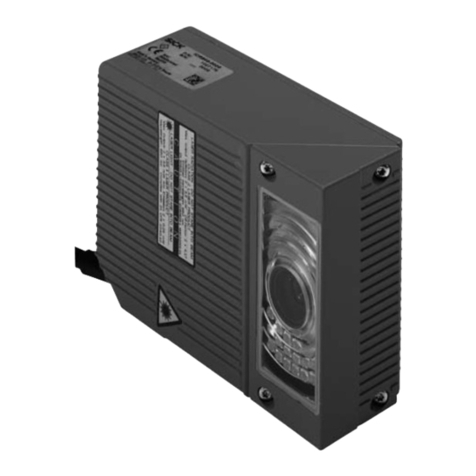
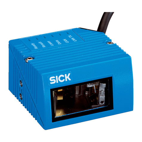
SICK CLV 210 User manual

1
Quick-Start
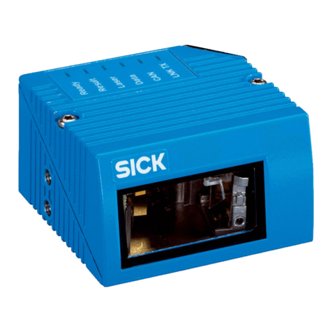
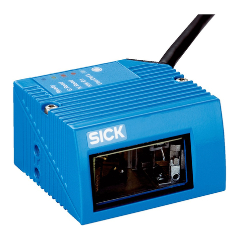
CLV 210...CLV 212 Bar Code Scanner
© SICK AG · Divi ion Auto Ident · Germany · All right re erved
8 007 825/01-2002
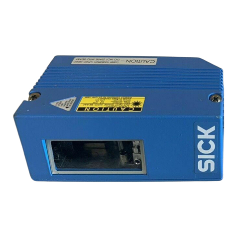
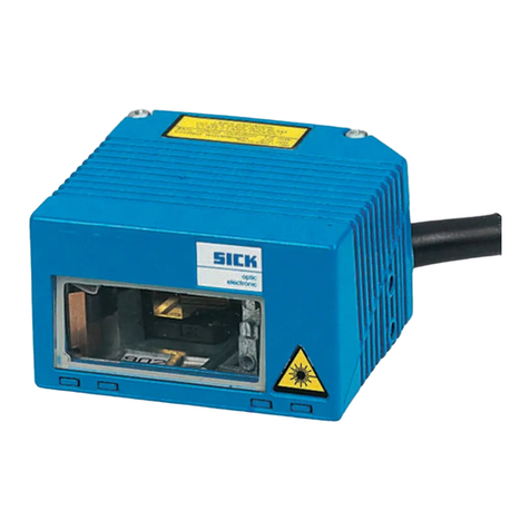
Fig 1. CLV 210...CLV 212 Bar Code Scanner
The CLV 210 to CLV 212, (referred to below a “CLV”), are u ed for automatic reading and decoding of bar
code in a tationary reading tation. The e “Quick Start” in truction de cribe the procedure for initial etup of
the device with the ba ic configuration et by the factory. Plea e refer to the
CLV 210...CLV 212 Operating In-
truction
(no. 8 007 042) for application- pecific configuration .
QUICK START
CLV 210...CLV 212 Bar Code Scanner
➌
➋
➊
➍
➏
➎
➏
➐
➎
Contents
Chapter Page
1. Plan view of device ....................................................................................... 1
2. Sy tem requirement ................................................................................... 2
3. Scope of delivery ........................................................................................... 2
4. La er warning ................................................................................................... 2
5. Electrical connection .................................................................................... 2
6. Function of the LED ................................................................................... 4
7. U er interface ................................................................................................... 5
8. Setup ..................................................................................................................... 6
9. Technical data .................................................................................................. 8
10. Reading field graph ...................................................................................... 9
11. Changing the alignment of the reading window ....................... 10
12. Dimen ioned diagram .............................................................................. 11
13. Specimen bar code for canning ...................................................... 11
1. Plan view of device
Legend:
➊ Sub D HD plug, 15-pin
➋ LED (function indicator )
➌ Connecting lead
➍ Angle attachment
➎ Threaded M5 mounting hole, 5 mm deep
➏ Angle attachment crew
➐ Reading window

Quick-Start
CLV 210...CLV 212 Bar Code Scanner
2
© SICK AG · Divi ion Auto Ident · Germany · All right re erved 8 007 825/01-2002
2. System requirements
The following are required to et up and operate the CLV via the auxiliary interface (RS 232):
• PC with terminal emulation program or a ba ic ASCII terminal
• AMV 40-011 connection module (no. 1 017 132) or AMS 40-013 (no. 1 017 135) from SICK
• RS 232 interface cable (e.g. no. 2 014 054 from SICK)
• voltage upply (24 V DC ±20 % for AMV 40 or 230 V AC (115 V) ±10 % for AMS 40)
3. Scope of delivery
The following are upplied with each CLV:
• "Quick Start" (German and Engli h)
• CLV 210...CLV 212 Menu Overview (German and Engli h, no. 8 007 661)
Depending on the number of device ordered, one or more of the following are upplied:
• CLV 210...CLV 212 Operating In truction (German, Engli h and French)
• a DOS di k (3.5 inch) with the "TERM" program from SICK (for PC)
4. Laser warning
5. lectrical connection
‡ Connect the CLV to the PC/terminal and 24 V DC (230 V AC) power upply via the AMV 40 (AMS 40)
connection module (a hown in
Fig. 3)
. The wiring configuration of the connection module i hown in the
AMV/AMS
Operating In truction
(no. 8 008 292).
Notes on electrical installation
• The 24 V DC external power unit mu t provide 3 W of continuou power for the AMV 40
Fig. 2. Warning attached to device
A la er-emitting device , the CLV 210... CLV 212 are cla ified
in protection cla 1. The IR light of the CLV 211 i not vi ible
to the human eye. The mo t recent ver ion of the relevant
la er-protection regulation , a defined by DIN EN 60825-1,
mu t be ob erved and applied when etting up the device. Thi
include avoiding looking into the beam directly and aiming the
device at other per on ( ee al o Chapter
4. La er protection
in
the
CLV 210...CLV 212 Operating In truction )
.
Laser warning:
LAS R CLASS 1
ð
Warning on the device:

3
Quick-Start
CLV 210...CLV 212 Bar Code Scanner
© SICK AG · Divi ion Auto Ident · Germany · All right re erved
8 007 825/01-2002
Fig. 4. Pin a ignment of the CLV 210...CLV 212: 15-pin D Sub HD connector/open cable end
5
1
96
AMV/AMS 40 PC/Terminal
Connection via connection module
24 V DC (AMV)
230 V AC (AMS)
"AUX"
connector
Fig. 3. Block diagram: connecting the CLV 210...CLV 212
RxD
TxD
GND
TxD
RxD
GND
2
3
5
PC/
terminal
AMV/
AMS 40
RS 232
e.g. cable
no. 2 014 054
Table 1
5 6
11
10
15
1
Pin Color Function Terminal Host interface1)
interfaces interface RS 232 RS 422/485 CL20 mA
1 red 24 V DC (in) - - - -
2 purple - RxD - - -
3 yellow - TxD - - -
4 red-black - - - Term2) -
5 black GND GND GND GND GND
6 light blue - - - RD+ R+
7 blue - - - RD- R-
8 light grey (turquoi e) ---TD+T+
9 green - - - TD- T-
10 grey - - RxD - -
11 pink - - TxD - -
12 brown Dev Rdy3) ----
13 orange Re ult3) ----
14 white Sen or4) ----
15 white-black Sen GND5) ----
white-green Screen
1) The CLV alway tran mit on the RS 232 and CL 20 mA (option: RS 422/485) interface.
One of the two interface mu t be activated via the Parametrization menu to
receive
data
(default: CL 20 mA interface)
2) Interface termination 3) Switching output 4) Switching input 5) ee
Fig. 5
CLV 210...212

Quick-Start
CLV 210...CLV 212 Bar Code Scanner
4
© SICK AG · Divi ion Auto Ident · Germany · All right re erved 8 007 825/01-2002
Connecting the function interfaces
The CLV require a uitable trigger ( witch, en or), a hown in
Fig. 5
, to trigger a reading proce (clocking) in
Reading mode.
In the tati tical
Percentage Evaluation
mode, the device operate independently of thi trigger
thu enabling the read function to be te ted directly. The connection of the two witching output "Device
Ready" and "Re ult" and the ho t interface are de cribed in the
CLV 210...CLV 212 Operating In truction
.
Fig. 5. "Sen or" reading-pul e input circuit for reading mode
L D Color Function
Device Ready green Indicate that the device i ready (reading mode).
Thi LED extingui he a oon a the device witche to a different mode. It ha the ame indicator
function a the "Device Ready" witching output
Sen or green Indicate that the la er diode i activated during the reading proce
Read Re ult green Corre pond to the "Re ult" witching output and it de igned pul e function
(default: Good read, pul e duration 100 m , non-inverted)
Data yellow Blink during data tran mi ion to the ho t
Table 3
6. Function of the L Ds
Switch
DC 24V
6K8
1
14
15
5
Sensor
GND
GND
DC 24V
DC 24V
Sens GND
CLV 210...CLV 212 PNP sensor
Switching function Start reading proce when the input i energized (ba ic etting)
Feature Opto-decoupled, non-interchangeable
Electrical value Low: -5V ≤ Vin ≤ +5 V
-0.5 mA ≤ Iin ≤ +0.5 mA
High: -30 V ≤ Vin ≤ -15 V
-2 mA ≤ Iin ≤ -5 mA
+15 V ≤ Vin ≤ +30 V
+2 mA ≤ Iin ≤ +5 mA
Table 2
24 V DC
24 V DC
24 V DC 1
14
15
5

5
Quick-Start
CLV 210...CLV 212 Bar Code Scanner
© SICK AG · Divi ion Auto Ident · Germany · All right re erved
8 007 825/01-2002
7. User interface
The CLV feature an integrated u er interface a well a four LED to how the actual operating tatu . To
operate and parametrize the device with a PC, a terminal emulation program (e.g. "TERM" from SICK) i required.
If the CLV i connected with a terminal, no additional u er oftware i nece ary. Enter “a: TERM/E” to call up the
TERM program in Engli h from di k in the a: drive on the PC.
‡ Choo e the following etting on the PC/terminal for the relevant port "Com x":
2 400 Bit / data tran mi ion rate, 8 data bit , no parity, 1 top bit
PC/terminal keyboard assignment
The four letter I, J, K and M on the keyboard are u ed to the control cur or in the menu. Pre ENTER to
confirm any change made or ESC to exit a menu item without aving the change (
Fig. 6
).
Fig. 6. Keyboard a ignment for controlling the cur or in the operating menu
The CLV only recogni e the e 6 key . An exception to thi , however, are the match code (alphanumeric
character ) which can be entered directly in Parametrization mode for the match code compari on.
Operation of the menu , which are largely elf-explanantory, i explained in
Table 4
.
Action PC/ASCII terminal
Calling the main menu from reading mode Pre [ ESC ] key twice
Selecting a menu item [ I ] key (up)
[ M ] key (down)
Calling Parametrization mode Select "Parametrization", confirm with [ ↵ ]
Selecting the next ubmenu level [ K ] or [ ↵ ]
Returning in the previou level [ J ] key
Changing the parameter value Select value Select with [ K ] key
Increa e or elect value with [ I ] key
Decrea e or elect value with [ M ] key
Confirm [ ↵ ] key
Cancel1) [ J ] key
Change mulit-digit parameter value Select po ition Select with [ K ] and [ J ] key
Increa e or elect value with [ I ] key
Decrea e or elect value with [ M ] key
Confirm [ ↵ ] key
Cancel1) [ J ] key
Exiting Parametrization mode, Select "Quit parameter " and confirm with [ ↵ ]
returning to the main menu
Returning to reading mode Select "Quit menu" and confirm with [ ↵ ].
Select de ired ave option and confirm with [ ↵ ].
1) Return the u er to the beginning of the re pective menu item
Table 4
&/( )=?`
67890ß´#
ZUOÜ*
+
GHJ K
IP
LÖÄ
^
BNM; : _
,.-
Eing
Lösch
4
1
End
0
Einfg
7
Pos1
➞
➞
➞
Groß
[ I ] key ➪[ ↑ ]
[ J ] key ➪[ ← ]
[ K ] key ➪[ → ]
[ M ] key ➪[ ↓ ]
[ ESC ] ➪[ ESC ]
[ ↵ ]➪[ Enter ]

Quick-Start
CLV 210...CLV 212 Bar Code Scanner
6
© SICK AG · Divi ion Auto Ident · Germany · All right re erved 8 007 825/01-2002
8. Setup
‡ Switch on the power upply 24 V DC for the CLV
The device witche to
Reading mode
automatically after the initialization procedure and elf-te t. The device
name and oftware ver ion are di played on the creen. The device then wait for a ignal from the external
en or to tart the reading function.
You mu t witch to
Percentage Evaluation
mode to read a bar code without a en or connected.
‡ Pre the [ ESC ] key twice; elect and confirm the "Percentage evaluation" menu item in the main menu.
‡ Hold the printed code ample in front of the reading window at a di tance of approx. 120 mm (CLV 210,
CLV 211) or 70 mm (CLV 212). The can line hould cro the code bar at a right angle (
Fig. 7
).
The device then evaluate 100 reading continuou ly and output the re ult on the creen a hown in
Fig. 8
.
Fig. 8. Example: read re ult on the creen for a ucce ful read
Fig. 7. Scan line/code a ignment
Line scanner Raster scanner
where:
T T= Duration of read interval
MG= Mean time value of identification quality
n= Number of code detected
C39= Code type code 39
100%= Identification quality
ST= Read tatu (0= Good read)
CP= Code po ition
CL= Code length
CA= Required can
CS= Code reliability
CK= Code continuity
UVWXYZ= Code content
T T= _ _160 m MG=_10% n=_1
C39 100% ST=0 CP=_46 CL=12 CA=_ _3 CS=109 CK=_ _1
UVWXYZ
Successful reading (Good read):
module width 0.35 mm
Code ample (Code 39):
UVWXYZ

7
Quick-Start
CLV 210...CLV 212 Bar Code Scanner
© SICK AG · Divi ion Auto Ident · Germany · All right re erved
8 007 825/01-2002
The meaning of the reading diagno i data i de cribed in the
CLV 210...CLV 212
Operating In truction ,
Chapter
11. Parametrization (Setup)
.
In the default etting ( tandard decoder), the device read
one
of the following code type with a canning/
decoding frequency of 250 Hz (CLV 210, CLV 211) or 200 Hz (CLV 212) and 3 multiple read :
Depending on the device type, the module width of the code u ed and the reading di tance mu t be a follow
for the default etting:
Device type Module width Reading distance
CLV 210 min. 0.33 mm approx. 40 ... 200 mm
CLV 211 min. 0.33 mm approx. 40 ... 190 mm
CLV 212 min. 0.10 mm approx. 50 ... 75 mm
Table 6
Decod. type Code types No. of useful characters1)
Standard Code 39 Free code length2)
2/5 interleaved Free code length2)
EAN 13 or 8
Codabar Free code length2)
Code 128 Free code length2)
1) Code length without tart and top character 2) up to 50 character (code 39 up to 49 character )
Table 5
‡ Pre the [ ESC ] key once to quit Percentage Evaluation mode. Following thi , quit the main menu by electing
"Quit menu". The device then return to
Reading mode
.
Switching off the device
• If no change have been made to the parameter in Parametrization mode, you can witch off the device in
Reading mode or in Percentage Evaluation mode directly without lo ing the configuration data. The default
etting are tored permanently in a non-volatile memory (ROM) and can be reloaded to the RAM at any time.
• If change have been made to the parameter value , the y tem a k you to elect one of the following ave
option when you exit the main menu: "permanent", "temporary" or "no change".
If you elect "no change", all of the change are lo t immediately. If you elect "temporary", all of the change are
only lo t when the device i witched off. "Permanent" ave all of the change to an EEprom and u e the e
change for operation. The CLV al o load the e parameter to the RAM when it i witched on again.
If no bar code are located within the can line, the error me age "no code!" i di played (
Fig. 9
).
Fig. 9. Example: “no read” re ult on the creen
Misread:
where:
T T= Duration of read interval
MG= Mean time value of identification quality
n= Number of code detected
no code = no code found!
T T= _ _160 m MG=_10% n=_0
no code !

Quick-Start
CLV 210...CLV 212 Bar Code Scanner
8
© SICK AG · Divi ion Auto Ident · Germany · All right re erved 8 007 825/01-2002
Type CLV 210 CLV 211 CLV 212
De ign Line canner, option: ra ter canner (not CLV 211) Line, Ultra-High-Den ity
Light ource (wavelength) Red light (λ= 670 nm) IR light (λ= 785 nm) Red light (λ= 670 nm)
Service life of la er diode MTBF 20,000 h
La er protection cla of device Red light: cla 1 (to DIN EN 60825-1)
U able aperture angle max. 60°
Light emi ion (reading window) lateral, angle attachment rotatable through 180°
Scanning/decoding frequency 200 ... 250 Hz 200 ... 250 Hz 200 ... 250 Hz
Re olution 0.2 ... 1.0 mm 0.2 ... 1.0 mm 0.1 ...1.0 mm
Reading range ( ee al o
Fig. 10
) 30 ... 270 mm 30 ... 250 mm 40 ... 95 mm
Bar code print contra t (PCS) ≥ 60 %
Ambient light compability 2000 lx (on bar code)
No. of code per reading gate/ can max. 3 (auto-di criminating)
Bar code type ( tandard decoder)1) Code 39, 2/5 interleaved, 2/5 indu trial (B), Codabar, EAN, UPC, code 128, code 93, EAN 128
Bar code length 2) max. 50 character (20 character in real-time)
Print ratio 2:1 ... 3:1
No. of multiple read 1... 99
Data interface “Ho t“ RS 232/CL 20 mA pa ive, optional: RS 232/RS 422/485, variable data output format
Data tran mi ion rate 300 ... 38 400 Bit /
Data interface “Terminal“ RS 232; 2400 Bit / , 8 data bit , 1 top bit, no parity; fixed data output format
Switching input / output 1 x IN (“Sen or”)/ 2 x OUT (“Device Ready” and “Re ult”)
Operating voltage/ power con umption 24 V DC ±20 %/ 2.5 W
Hou ing Die-ca t zinc
Enclo ure rating/ protection cla IP 65 (to DIN 40 050)/ Cla 3 (to VDE 0106)
EMC/ vibration/ hock te t To IEC 801/ to IEC 68-2-6 Te t FC/ to IEC 68-2-27 EA Te t
Dimen ion (L x W x H) 113 mm x 68 mm x 32 mm (lateral reading window)
Weight approx. 600 g with connecting lead (0.9 m)
Ambient operating/ torage temperature 0 ... +40 °C/ –20 ... +70 °C
Max. relative humidity 90 %, non-conden ing
1) half code decoder: the code type 2/5 indu trial, 2/5 indu trial B and Codabar do not apply 2) code 39: up to max. 49 character
Table 7
Application-specific configuration
For a pecial, more detailed reading ta k we recommend that the device be configured on ite in the reading
tation. Plea e u e the more detailed CLV 210...CLV 212 Operating In truction .
The Parametrization menu i divided into four ection :
1. code configuration
2. device configuration
3. ho t interface
4. auxiliary interface
We recommend that the parameter be defined in thi equence. The meaning of the individual parameter and
the permi ible value are de cribed in Chapter
11. Parametrization (Setup)
in
the CLV 210...CLV 212 Operating
In truction
. The
CLV 210...CLV 212 Menu Overview
enclo ed i intended to help you navigate through the
menu (the default value are highlighted in bold).
9.Technical data
9
Quick-Start
CLV 210...CLV 212 Bar Code Scanner
© SICK AG · Divi ion Auto Ident · Germany · All right re erved
8 007 825/01-2002
10. Reading field graphs
Fig. 10. Reading range of CLV 210...CLV 212
Straight window alignment: the reading field i 15 mm further away from the reading window
Ra ter canner: ra ter height of 15 mm at a reading di tance of 200 mm
[mm]
0
100 120
0 20 40 60 80
60
20
20
40
60
[mm]
40
0.1 mm
0.15 mm
0.2 mm
0.35 mm
CLV 212 (Ultra-High Density)
CLV 211 (IR light)
0
250 300
0 50 100 150 200
150
100
50
50
100
150
[mm]
[mm]
0.2 mm
0.35 mm
0.5 mm
1.0 mm
CLV 210 (standard)
Scanning frequency 200...250 Hz
Reading conditions
Te t code code 39/ITF
Print ratio 3:1
Print contra t > 90 %
Skew 15°
Tilt 10°
Ambient light < 2000 lx
Good read rate > 75 %
Table 8
Reading di tance
Reading di tance Reading di tance
Reading field height
Scanning frequency 200...250 Hz Scanning frequency 200 Hz
Reading field height
0
250 300
0 50 100 150 200
150
100
50
50
100
150
[mm]
[mm]
0.2 mm
0.35 mm
0.5 mm
1.0 mm

Quick-Start
CLV 210...CLV 212 Bar Code Scanner
10
© SICK AG · Divi ion Auto Ident · Germany · All right re erved 8 007 825/01-2002
11.Changing the alignment of the reading window
The alignment of the reading window can be changed a hown in
Fig. 11
:
‡ Starting from the lateral light emi ion configuration (a delivered), loo en the two crew ➅ on the angle
attachment ➆
‡ Remove the angle attachment carefully and turn it through 180° o that the reading window i now parallel
with the back of the CLV
‡ Tighten the angle attachment in the new po ition u ing the two crew ➅
Note:
With traight window alignment, the reading field i 15 mm further away from the reading window.
Fig. 11. Changing the alignment of the reading window
ð
Straight window
alignment
Lateral reading
window alignment
➏
➏
➐
IMPORTANT:
Alway witch off the power upply to
the CLV before removing the angle
attachment.
Switch off the 24 V DC voltage upply!
En ure that the urrounding area i free
of du t to prevent dirt from entering
the device.

11
Quick-Start
CLV 210...CLV 212 Bar Code Scanner
© SICK AG · Divi ion Auto Ident · Germany · All right re erved
8 007 825/01-2002
12. Dimensioned diagram
All dimen ion in mm
Fig. 13. Code ample for etup of CLV (te ting)
Fig 12. Dimen ion of CLV 210...CLV 212
13. Specimen bar codes for scanning
Module width
0.25 mm
A123456A
CLV
A3
2/5 interleaved
EAN 13-digit
Codabar
code 39 code 128
Module width
0.35 mm
Module width
0.50 mm
Module width
0.75 mm
Module width
1.00 mm
9.5
9876543210
4 096072 616559

Singapore
SICK Optic-Electronic Pte. Ltd.
701 Sims Drive, # 03-0
LHK Building
Singapore 387 383
ꇴ+65 744 373
Fax: +65 841 7747
Spain
SICK Optic-Electronic S.A.
Apartado Postal 5
Constitución, 3
E-08960 Sant Just Desvern
ꇴ+34 93 4 80 31 00
Fax: +34 93 4 73 44 69
Sweden
SICK AB
Botkyrkavägen 4
S-14335 Vårby
ꇴ+46 8-680 64 50
Fax: +46 8-710 18 75
Switzerland
SICK AG
Breitenweg 6
6370 Stans
ꇴ+41 41 61 9 93 9
Fax: +41 41 61 9 9 1
Taiwan
SICK Optic-Electronic Co., Ltd.
No. 55, 1 Fl., Shoei Yuan Road
P. O. Box 30-6 TAIPEI
100, TAIWAN, ROC
ꇴ+886 365-6 9
Fax: +886 368-7397
Further representatives and
agents in all major industrial
nations.
E3305sw8 007 8 5/01- 00 . 5M/TR <PM 6.0> . SMD . Printed in Germany . Subject to change without prior notice . "QS 1x, Engl."
France
SICK
BP 4
F-7731 Marne la Vallée
Cedex 0
ꇴ+33 1 64 6 35 00
Fax: +33 1 64 6 35 77
Germany
SICK AG
Schiess-Straße 56
40549 Düsseldorf
ꇴ+49 11 53 01-0
Fax: +49 11 53 01-1 00
Italy
SICK S.p.A.
Strada Padana Superiore, 53
0063 Cernusco sul Naviglio (Milano)
ꇴ+39 0 -9 14 0 6
Fax: +39 0 -9 14 0 67
Japan
Sick K. K.
5-8-8 Shinjuku, Shinjuku-ku
Tokyo 160-00
ꇴ+81 3 3358 1341
Fax: +81 3 3358 0586
Netherlands
SICK B.V.
Postbus 186
Leijenseweg 111
NL-37 0 AD Bilthoven
ꇴ+31 30 9 5 44
Fax: +31 30 9 39 94
Laser Measurement Systems:
SICK Instruments Benelux
Sales and Service Office
Veldweg 6C
NL-53 1 JE Hedel
ꇴ+31 73 599 50 44
Fax: +31 73 599 47 18
Norway
SICK AS
Baerumsveien 383
N-1346 Gjettum
ꇴ+47 67 56 7500
Fax: +47 67 56 6100
Poland
SICK Sp. z. o. o.
ul. Nakielska 3
01-106 Warszawa
ꇴ+48 837 40 50
Fax: +48 837 43 88
Austria
SICK GmbH
Straße A, Objekt M11, IZ NÖ-Süd
355 Wiener Neudorf
ꇴ+43 36 6 8 8-0
Fax: +43 36 6 8 85
Belgium/Lu embourg
SICK N.V./S.A.
Industriezone Doornveld 6
B-1731 Asse (Relegem)
ꇴ+3 4 66 55 66
Fax: +3 4 63 31 04
Laser Measurement Systems:
SICK Instruments Benelux
Sales and Service Office
Blekerijstraat 75
B-9000 Gent
ꇴ+3 9 40 394
Fax: +3 9 35 645
Brazil
Sick Indústria & Comércio Ltda.
Rua Conde de Porto Alegre,
No. 1633, São Paulo,
SP 04608-003
ꇴ+55 11 5561 683
Fax: +55 11 5535 4153
China
Sick Optic-Electronic Co., Ltd.
Unit D, 16/F China Trade Centre
1 -1 4 Wai Yip Street,
Ngau Tau Kok
Kowloon, Hong Kong
ꇴ+85 763 6966
Fax: +85 763 6311
Czech Republic
SICK spol. s r. o.
Námesti Osvoboditelu 1368
CZ-15300 Praha 5-Radotin
Czech Republic
ꇴ+4 0 -579 11 850
+4 0 -578 10 561
Fax: +4 0 -578 10 559
Denmark
SICK A/S
Datavej 5
DK-3460 Birkerød
ꇴ+45 45 8 64 00
Fax: +45 45 8 64 01
Finland
Sick Optic-Electronic Oy
Niittyläntie 5
SF-006 0 Helsinki
ꇴ+358 9-7 8 85 00
Fax: +358 9-7 88 50 55
Great Britain
Erwin Sick Ltd.
Waldkirch House
39 Hedley Road, St. Albans
Hertfordshire AL1 5BN
ꇴ+44 17 7-83 11 1
Fax: +44 17 7-85 67 67
USA
SICK, Inc.
6900 West, 110th Street
Bloomington, MN 55438
ꇴ+1(95 ) 941-6780
Fax: +1(95 ) 941-9 87
WATS: 1-800-3 5-74 5
Australia
Erwin Sick Optic-Electronic
Pty. Ltd. Head Office
P. O. Box 14
899 Heidelberg Road
Ivanhoe, Vic. 3079
ꇴ+61 3 9497 4100
(0 08) 33 48 0 - toll free
Fax: +61 3 9497 1187
SICK AG
Division Auto Ident
Nimburger Straße 11
79 76 Reute
Germany
www.sick.de
This manual suits for next models
2
Table of contents
Other SICK Barcode Reader manuals

SICK
SICK CLV640 User manual

SICK
SICK CLV61 DualPort Series User manual

SICK
SICK CLV63 Series User manual

SICK
SICK Lector62 Series Reference guide

SICK
SICK Lector85 Flex Series User manual

SICK
SICK CLV62 Series User manual

SICK
SICK CLV63 Series Manual

SICK
SICK CLV 420 User manual

SICK
SICK CLV61x FIELDBUS Series User manual

SICK
SICK CLV61 DualPort Series Manual

SICK
SICK CLP 100 User manual

SICK
SICK CLV 490 Series User manual

SICK
SICK CLV622 User manual

SICK
SICK ICR 84x User manual

SICK
SICK ICR803 User manual

SICK
SICK CLV 41 Series User manual

SICK
SICK Lector61x User manual

SICK
SICK Lector61 Series User manual

SICK
SICK CLV62 Series Manual

SICK
SICK CLV 490 User manual