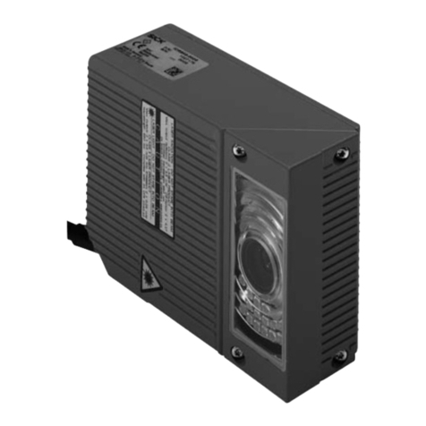
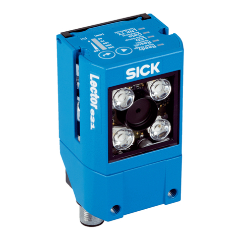
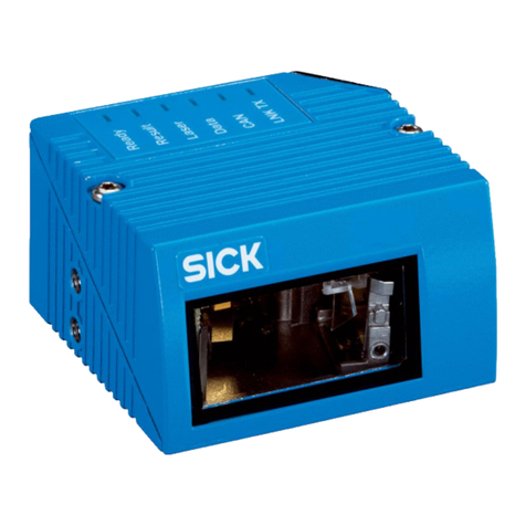
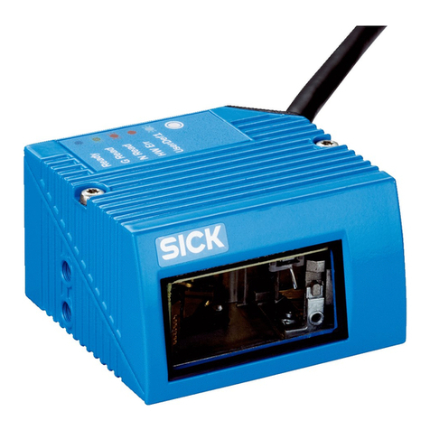
SICK ICR845-2 User manual

OPERATING INSTRUCTIONS
2D Line
ICR845-2
Image Code Reader

Operating Instructions
ICR845-2 Image Code Reader
2©SICK AG ·Division Auto Ident ·Germany·All rights reserved 8012377/ 0000/ 2008-01-30
Software Versions
Software Versions
RF interferences in case of use in residential areas!
The ICR845-2 Image Code Reader is exclusively intended for use in industrial areas.
Copyright
Copyright
2008
SICK AG Waldkirch
Auto Ident, Reute Plant
Nimburger Strasse 11
79276 Reute
Germany
Trademarks
Windows 95
TM
/
98
TM
, Windows NT
TM
, Windows 2000
TM
, Windows XP
TM
and Internet
Explorer
TM
are registered trademarks or trademarks
of the Microsoft Corporation in the USA
and other countries.
Adobe
TM
Reader
TM
is a trademark of Adobe Systems Incorporated.
Latest manual version
For the lastest version of this manual (PDF), see
www.sick.com
.
Software/Tool Function Version
ICR845-2 Firmware V3.10
CLV-Setup Configuration software (Windows-based) V4.6
CLV-Setup Help Onlinehelp (HTML) V4.6
ImageFTP Image transfer and presentation software V2.1.0.1

Operating Instructions
ICR845-2
8012377/0000/2008-01-30
©SICK AG·Division Auto Ident ·Germany·All rights reserved 3
Contents
Table of Contents
1 Noteson this document.................................................................................................7
1.1 Purpose.....................................................................................................................
....7
1.2 Target group................................................................................................................
.7
1.3 Depth of information ...................................................................................................7
1.4 Used symbols...............................................................................................................8
2 SafetyInformation..........................................................................................................9
2.1 Authorized users..........................................................................................................9
2.2 Intended use................................................................................................................9
2.3 General safetyprecautions and protection measures...........................................10
2.4 Quick stop and quick restart....................................................................................12
2.5 Environmental information.......................................................................................12
3 Product description......................................................................................................13
3.1 Design of device........................................................................................................13
3.2 System requirements...............................................................................................16
3.3 Product features and functions(overview).............................................................16
3.4 Method of operation.................................................................................................18
3.5 Indicators and control elements..............................................................................20
4 Installation ....................................................................................................................23
4.1 Overviewof installation sequence...........................................................................23
4.2 Installation preparations..........................................................................................23
4.3 Installation location..................................................................................................25
4.4 Installing and adjustingthe ICR845-2.....................................................................29
4.5 Installingexternal components................................................................................29
4.6 Removing the device................................................................................................30
5 Electrical installation...................................................................................................31
5.1 Overviewof the installation sequence....................................................................31
5.2 Electrical installation preparations..........................................................................31
5.3 Electrical connections and cables...........................................................................33
5.4 Pin assignments........................................................................................................36
5.5 Performingelectrical installation.............................................................................37
5.6 Pin assignment and wire coulou
r assignment of pre-fabricated
cables with open ends..............................................................................................45
6 Startup and configuration...........................................................................................47
6.1 Overviewot the startup procedure..........................................................................47
6.2 CLV-Setup configuration software...........................................................................47
6.3 Establish communication with the ICR845-2 .........................................................48
6.4 The image transfer program ImageFTP...................................................................58
6.5 Usingthe function key..............................................................................................68
6.6 First startup...............................................................................................................
69
6.7 Establish communciation with theICR845-2 manually.........................................70
6.8 Configuringthe ICR845-2.........................................................................................71
6.9 Operatingmodes and outputtingthe readingresult..............................................74
6.10 ICR845-2 messages.................................................................................................89
6.11 Default settings.........................................................................................................91
6.12 Adjustingthe ICR845-2............................................................................................93
6.13 Configuration guide..................................................................................................94
6.14 Switchingthe ICR845-2 off....................................................................................100
7 Maintenance...............................................................................................................101
7.1 Maintenance duringoperation ..............................................................................101
7.2 Cleaningthe ICR845-2 ...........................................................................................101
7.3 Checkingthe incremental encoder........................................................................103
7.4 Replacingan ICR845-2 ..........................................................................................103
7.5 Disposal...................................................................................................................1
04
8 Troubleshooting..........................................................................................................105
8.1 Overview of errors and malfunctionswhich could occur.....................................105
Operating Instructions
ICR845-2 Image Code Reader
4©SICK AG·Division Auto Ident ·Germany·All rights reserved 8012377/0000/ 2008-01-30
Contents
8.2 Monitoringerrors and malfunctions......................................................................105
8.3 Error messages.......................................................................................................106
8.4 STerror status in the readingresult of an 1D code (bar code)...........................107
8.5 Troubleshooting......................................................................................................109
8.6 SICK Service............................................................................................................119
9 Technical data............................................................................................................121
9.1 Data sheet for the ICR845-2 Image Code Reader...............................................121
9.2 ICR845-2 dimensional drawing ............................................................................123
9.3 Specification diagram ............................................................................................124
10 Appendix.....................................................................................................................
125
10.1 Appendixoverview..................................................................................................125
10.2 Settings for readingData MatrixECC200 ............................................................126
10.3 System messages...................................................................................................135
10.4 Installation and operating
instructions for the CLV-Setup
configuration software...........................................................................................136
10.5 Configuringthe ICR845-2 with command strings................................................146
10.6 Auxiliarytables........................................................................................................148
10.7 Special applications and procedures....................................................................149
10.8 Orderinginformation for ICR845-2 and accessories...........................................164
10.9 Dimensional drawings accessories.......................................................................169
10.10 Supplementarydocumentation.............................................................................171
10.11 Glossary...................................................................................................................172
10.12 EC-Declaration of Conformity.................................................................................178
10.13 List of tables and figures .......................................................................................179
10.14 Index........................................................................................................................183
10.15 Code samples (selection).......................................................................................187

Operating Instructions
ICR845-2
T
ables and Figures
8012377/0000/2008-01-30
©SICK AG·Division Auto Ident ·Germany·All rights reserved 5
Abbreviations
CAN C
ontroller
A
rea
N
etwork (field bus protocol based on the CAN bus)
CDB C
onnection
D
evice
B
asic
CDM C
onnection
D
evice
M
odular
DPM D
irect
P
art
M
arking
DOF D
epth
o
f
F
ield
DPS D
ynamic
P
arameter
S
witching
DSP D
igitaler
s
ignal
p
rocessor
EEPROM E
lectrically
E
rasable
P
rogrammable
R
ead
O
nly
M
emory.
FIFO F
irst
i
n,
f
irst
o
ut
HD H
igh-
D
ensity
HTML H
yper
T
ext
M
arkup
L
anguage (languages of internet websites)
ICR I
mage
C
ode
R
eader
LED L
ight
E
mitting
D
iode.
LIFO L
ast
i
n,
f
irst
o
ut
MTBF M
ean
T
ime
B
etween
F
ailure
PLC P
rogrammable
L
ogic
C
ontroller
RAM R
andom
A
ccess
M
emory
ROI R
egions
o
f
I
nterest
ROM R
ead
O
nly
M
emory
RTF R
ich
T
ext
F
ormat (standardised document format with format descriptions)
SMART S
ICK
M
odular
A
dvanced
R
ecognition
T
echnology
Important
For a list of tables and figures see
Chapter 10.13 List of tables and figures, Page 179.

Operating Instructions
ICR845-2 Image Code Reader
6©SICK AG·Division Auto Ident ·Germany·All rights reserved 8012377/0000/ 2008-01-30
Tables and Figures

Operating Instructions
Chapter
1
ICR845-2
Notes on this document
8012377/0000/2008-01-30
©SICK AG·Division Auto Ident ·Germany·All rights reserved 7
1
Notes on this document
1.1 Purpose
This document provides instructions for
technical staff
on the installation and operation of
the ICR845-2 Image Code Reader (fixed focus) in following versions:
Mid Range reading range
Front / side reading window
A summary of all device versions is shown in
Chapter 3.1.4 Device versions, Page 15.
This document provides information on
Installation and electrical installation
Startup
Configuration
Maintenance
Troubleshooting
Replacing the device
Special applications and procedures
Important
The ICR845-2 Image Code Reader with all its variants is simply referred to as "ICR845-2" in
the document, except where a distinction is necessary.
1.2 Target group
This document is intended for persons who are responsible for the following activities:
1.3 Depth of information
This document contains all of the informat
ion necessary for the installation, electrical
installation and startup of the ICR845-2 with the
factory default settings
.
The ICR845-2 is configured for the
application-specific reading conditions
using the CLV-
Setup configuration software on a Windows
TM
PC. The CLV-Setup configuration software
contains the online help system CLV-Setup Help
to facilitate configuration. The procedure
for installing and operating the configuration software is described in the Appendix.
Important
Additional information on the structure of the ICR845-2 Image Code Reader and 1D/2D
code technology is available from th
e Auto Ident division of SICK AG.
Internet address:
www.2d-code.com
.
Tasks Target group
Installation, electrical installation, main-
tenance and replacement
Qualified staff, e.g. electricians and service technicians
Startup and configuration Qualified staff, e.g. technicians and engineers
Tab. 1-1: Target group

Chapter
1
Operating Instructions
ICR845-2 Image Code Reader
8©SICK AG·Division Auto Ident ·Germany·All rights reserved 8012377/0000/ 2008-01-30
Notes on this document
1.4 Used symbols
Some of the information in this document is marked specially so that you can access it
quickly:
Warning notice!
A warning notice indicates real or potential da
nger. It is intended to prevent accidents and
to protect the ICR845-2 Image Code Reader from damage.
Always read warning notices carefully and observe them at all times.
Reference
Italic script denotes a reference to further information.
Important
This important note informs you of specifc features.
Explanation
Explanations provide background information on technical correlations.
Recommendation
Recommendations help you carry out ce
rtain procedures more effectively.
Tip
Tips explain settings CLV-Setup configuration software.
Default setting
Marks a section containing the values of the factory default settings.
S
CANNING
FREQUENCY
This font indicates a term in the user interface of the CLV-Setup configuration software.
Icons refer to buttons in the user interface of the CLV-Setup configuration software.
"Host receive fault"
This font indicates messages output via
the auxiliary interface of the ICR845-2.
This symbol identifies sections that describe steps carried out with the user interface of the
CLV-Setup configuration software.
This symbol refers to additional technical documentation.
There is a procedure which needs to be carried out. This symbol indicates operational in-
structions which only contain one operational step or operational steps in warning notices
which do not to have be followed in any particular order.
Operational instructions comprising several
steps are denoted using consecutive numbers.
This symbol indicates either the selection of a function in the CLV-Setup configuration soft-
ware or indicates a reference in the glossary.

Operating Instructions
Chapter
2
ICR845-2
Safety Information
8012377/0000/2008-01-30
©SICK AG·Division Auto Ident ·Germany·All rights reserved 9
2
Safety Information
This chapter deals with your safety and operator safety in the opertional area.
Read this chapter carefully
before
using the ICR845-2.
2.1 Authorized users
For correct and safe functioning, the ICR845-2 must be installed, operated and maintained
by sufficiently qualified staff.
Repairs to the ICR845-2 should only be carr
ied out by qualified and authorised SICK AG
service staff.
Supplied the end user with the operating instructions.
Provide the end user with expert tuition and advise him to read the operating instruc-
tions.
The following qualifications are required for the various tasks involved:
2.2 Intended use
The ICR845-2 is an intelligent sensor for the automatic reading and decoding of 1D codes
(bar codes) and 2D codes on objects in a read
ing station. The sensor is optimised to appli-
cations in which the codes are read either on objects transported with high velocity or on
not moved objects.
The ICR845-2 transfers the reading data via its host interface (serial RS 232/422/485 or
Ethernet) to a host computer for further processing.
The ICR845-2 is configured/operated using the CLV-Setup configuration software that runs
on a standard client PC (Windows
TM
) provided by the customer.
Important
Any warranty claims against SICK AG shall be
deemed invalid in the case changes to the
device, such as opening the housing, this in
cludes modifications du
ring installation and
electrical installation or changes to the SICK software.
The ICR845-2 is only to be operated in the permitted ambient air temperature range.
Tasks Qualifications
Installation, maintenance – General technical training
– Knowledge of the standard guidelines relatingto safetyin the work-
place
Electrical installation,
replacement
– Practical electrical training
– Knowledge of the common electrical safetyguidelines
– Knowledgeregardingtheoperation of thedevicesin therelevant ap-
plication (e.g. conveyor belt)
Startup, configuration – Basis knowledge of the Windows
TM
operating system
– Basis knowledge of designing and settingup (adressing) Ethernet
connections for connecting the ICR845-2 to the Ethernet
– Basis knowledge of workingwith an HTMLbrowser (e.g. Internet
Explorer
TM
) for using the online help
– Basic knowledge of data transfer
– Basic knowledge of 1D/ 2Dcode technology
Operation of the devices in
each operational area
– Knowledge regardingthe operation of the devices in the relevant
application (e.g. conveyor belt)
– Knowledge of the hardware and software environment of the rele-
vant application (e.g. conveyor belt)
Tab. 2-1: Required qualifications for startingup the ICR845-2

Chapter
2
Operating Instructions
ICR845-2 Image Code Reader
10
©SICK AG·Division Auto Ident ·Germany·All rights reserved 8012377/0000/ 2008-01-30
Safety Information
2.3 General safetyprecautions and protection measures
Read the general safety precautions carefully and observe them at all times. This also
applies to the warnings and operating instructions in the individual chapters of this doc-
ument.
2.3.1 RFinterferences
RF interferences in case of use in residential areas!
The ICR845-2 Image Code Reader is exclusively intended for use in industrial areas.
2.3.2 Electrical installation
Risk of injury by electrical current!
In the CDM420 Connection Module, the CMP400 Power Supply Module is connected to a
mains voltage of 100 to 250 V AC/50 to 60 Hz.
When working with electrical equipment, always follow the relevant safety regulations.
Important
Electrical installation should only be carried out by qualified staff.
Connect or disconnect current linkages only under de-energised conditions.
Wire cross sections and their correct protection have to be selected and implemented ac-
cording to valid engineering standards.
2.3.3 LEDradiation
LED radiation!
The illumination of the ICR845-2 op
erates with LEDs of LED class 1.
Under normal and sensible conditions, the accessible radiation of the LEDs is not hazard-
ous. Blinding, impairment of ability to see color, or other irritations, however cannot be ex-
cluded.
The entire area of the reading window (
Fig. 2-1
) acts as a LED outlet aperture.
Caution – use of controls or adjustments or performance of procedures other than those
specified herein may result in hazardous radiation exposure.
Never look directly into the illumination.
Do not open the housing.
(Opening the housing does not deactivate the LEDs by the reading pulse.)
Always observe the latest valid version of laser protection regulations.
Radiation power
The illumination LEDs operate at a wavelength of
= 617 nm
15 nm (visible red light)
with a pulse duration of max. 5 ms. The energy in the human eye is < 2.1 J/m
2
.

Operating Instructions
Chapter
2
ICR845-2
Safety Information
8012377/0000/2008-01-30
©SICK AG·Division Auto Ident ·Germany·All rights reserved
11
The product is classified in LED class 1 in
accordance with EN 60825-1 and IEC 60825-1
(for publication date, see the warning sign on the device).
Important
Maintenance is not required to ensure compliance with LED class 1.
Warning labels
At the ICR845-2, the warning label (
Fig. 2-2
) in three languages and the warning symbol are
located on the wide side of the housing.
If the ICR845-2 is installed in a machine/panel with the result that the warning labels are
no longer visible, additional warnings (not included in the scope of delivery) must be pro-
vided on the machine beside the emergence aperture of the LED radiation.
Controlling the illumination LEDs
Activation and deactivation of the LEDs when reading is controlled by the reading pulse
(trigger source).
A timer (illumination timeout) automatically
deactivates the LEDs 10 minutes (default
setting) after a continuous reading pulse is initiated in Reading mode with switching in-
put pulse modes "Sensor Input" and "Serial
Interface". However, it does not end the
Fig. 2-1: Outlet opening of the LEDradiation at the ICR845-2
Outlet opening
(entire window area)
Fig. 2-2: Black-yellowsigned warninglabels found on the ICR845-2

Chapter
2
Operating Instructions
ICR845-2 Image Code Reader
12
©SICK AG·Division Auto Ident ·Germany·All rights reserved 8012377/0000/ 2008-01-30
Safety Information
reading interval. In this case, the ICR845-2
outputs the following message to the auxil-
iary interface:
"Illumination safety timeout"
The reading interval must be terminated by resetting the trigger signal. The LEDs are
activated again by the next reading pulse.
Theillumination timeout can beset in therangeof 1 min to 25 h or deactivated.
The illumination LEDs are periodically activated in the operating mode "Percentage
Evaluation" and are always activated in the pulse mode "Free Running" in Reading
mode.
2.4 Quick stop and quick restart
2.4.1 Switching the ICR845-2 off
Switch off the power supply or remove the ICR845-2 cable plug from the connection
module.
This can result in loss of the following (at the most):
The application-specific paramete
r set, if it was only stored
temporarily
in the ICR845-2
The last reading result
Daily operating data
(operating hours counter, reading interval co
unt, good read count, no read count, max-
imum duration reading interval, minimum duration reading interval, number of match-
es with match code 1, number of matches with match code 2, number of No Matches.)
2.4.2 Switching the ICR845-2 on again
Switch on the supply voltage or reattach the ICR845-2 cable plug to the connection
module.
The ICR845-2 resumes operation with the
last permanently stored
parameter set and
resets the daily operating data.
2.5 Environmental information
The ICR845-2 is designed to cause minimum im
pact on the environment. It does not con-
tain any silicone-based materials on the housing surface and, therefore, does not represent
any problems for paint sprayers in paint shops, for example.
2.5.1 Power requirements
The power requirements are low: The ICR845-2 has a maximum power consumption of typ-
ically 13 W. The value is given for devices with disconnected switching outputs.
2.5.2 Disposal after final removal from service
At present SICK AG does not take back device
s which have become unusable or irreparable.
Dispose of unusable or irreparable devices in
accordance with the respective state reg-
ulations on waste disposal in a manner compatible with the environment.
The ICR845-2 can be separated into recyclable
secondary raw materials and special-cate-
gory waste (electronic scrap).
See
Chapter 7.5 Disposal, Page 104.

Operating Instructions
Chapter
3
ICR845-2
Product description
8012377/0000/2008-01-30
©SICK AG·Division Auto Ident ·Germany·All rights reserved
13
3
Product description
This chapter describes the design, the fe
atures and the functions of the ICR845-2.
For installation, electrical installation and
startup assistance as well as for the applica-
tion-specific configuration of the ICR845-2 using the CLV-Setup configuration software,
please read this chapter
prior
to carrying out any of the tasks.
3.1 Design of device
The ICR845-2 consists of a image recording system (lense and CMOS matrix sensor with
global shutter) and an electronic unit (image
processing system with integrated decoder).
The image recording system and the electronic unit are located in an industry-compatible
housing. The light exits and enters via a reading window in the housing, which also contains
an arrangement of LEDs for illuminating the reading area.
For an adaptation to on-site space conditions
two housings are available: a housing with
front reading window and a housing with side
reading window. Via the integrated angle at-
tachment, the reflected light enters through the side reading window at an angle of 90
re-
ferred to the centre-line of the housing.
Depending on the type, various lenses enable
different resolutions and reading ranges.
The ICR845-2 is electrically connected by a shielded cable with a D-Sub HD plug and by an
RJ45 socket on the housing. The ICR845-2 meets the enclosure rating IP 65 using an optio-
nal adapter frame with the corresponding Ethernet cable or a corresponding cover.
Fig. 3-1, Page 14
shows the view of the ICR845-2.

Chapter
3
Operating Instructions
ICR845-2 Image Code Reader
14
©SICK AG·Division Auto Ident ·Germany·All rights reserved 8012377/0000/ 2008-01-30
Product description
3.1.1 View of device
Fig. 3-1: Design of the ICR845-2
Side reading window
Key:
D-Sub HD cable plug, 15-pin
Tapped blind hole M5, 8 mm (0.31 in)
deep, for mounting the ICR845-2
Reading window with lens and
illumination LEDs
Tapped hole M3, 5.5 mm (0.22 in) deep,
for mounting the IP 65 adapter frame
RJ45 10baseT socket for
Ethernet connection, with LEDs
Function key
LEDs (status indicators)
Warning labels
Connection cable
Front reading window

Operating Instructions
Chapter
3
ICR845-2
Product description
8012377/0000/2008-01-30
©SICK AG·Division Auto Ident ·Germany·All rights reserved
15
3.1.2 Scope of delivery
Delivery of the ICR845-2 includes the following components:
An overview of in-stock installation accessories, connection modules, sensors for reading
pulses, incremental encoder, cables and plug-in connectors is available in
Chapter 10.8 Or-
deringinformation for ICR845-2 and accessories, Page 164.
3.1.3 Contents of the CD-ROM (Nr. 2029112)
CLV-Setup
: Configuration software for standard PC (Windows
TM
) with integrated
online help system CLV-Setup Help (HTML files)
CLV-Connect
: Presentation software for standard PC (Windows
TM
) for displaying connec-
tion diagrams (HTML files)
ICR845-2 operating instructions
: PDF version in German and English as well as further
publications of other SICK devices (c
onnection modules, bar code scanners)
Adobe Reader
: Freely available PC software for displaying PDF files
Important
All current versions of publications and prog
rams on the CD-ROM can also be downloaded
at
www.sick.com
.
3.1.4 Device versions
The ICR845-2 is available in the following versions:
Important
Other versions on request.
No. Component Comment
1 ICR845-2 Image Code Reader Type depends on version, see Tab. 3-2
1 Noteson devicewith electrical connection dia-
gram and quick start as primary information
Included in the device packing of the
ICR845-2
1 CD-ROM "Manuals & Software Bar Code Scan-
ners"
Included in the device packing of the
ICR845-2
ICR845-2 Operating Inst
ructions in printed
form, in German and/or English
Optional, depending on the number of
issues explicitly ordered upon purchase
Tab. 3-1: ICR845-2 delivery
Type (red light) Order no. Version Reading window
ICR845-2C0020 1043740 Mid Range On front
ICR845-2C1020 1043739 On side
Tab. 3-2: Versions of the ICR845-2

Chapter
3
Operating Instructions
ICR845-2 Image Code Reader
16
©SICK AG·Division Auto Ident ·Germany·All rights reserved 8012377/0000/ 2008-01-30
Product description
3.2 System requirements
General system requirements are devired from the technical data of the ICR845-2 (see
Chapter 9 Technical data, Page 121
).
The requirements and conditions for
Installation
,
Electrical installation
and
Startup and
configuration
are summarised in the respective chapters.
3.3 Product features and functions (overview)
Feature Characteristic
High-performance reader
CMOS matrix sensor of newest technology (WVGA resolution)
Fixed focus
Front reading window or side reading window
Resolution, reading range (DOF) and field of view depending on type (Mid Range)
60 Hz Image recording rate at full field of view
Function to adapt to the code marking quality/object velocity
Variable active evaluation range of the matr
ix sensor, thereby higher image recording rate
Safety and user-friendly features
Robust, compact metal housing, max. IP 65, CE certification
LED class 1, illumination LEDs switches off if reading interval is active for too long
Automatic self-test on startup. Can also be triggered at any time
Diagnosis tools for installing and monitoring the system
Variable output of reading diagnosis data in the read result
Operating data query, and error messages on request
Test string function for sign
aling readiness for operation
Future proof thanks to firmware update via data interface (flash PROM)
Low power consumption
Extended power voltage range
Easy configuration
Configuration (online/offline) via CLV-Setup configuration software with integrated Assist-
ant (Connection Assistant) and help system.
Displaying the image memory content via the ImageFTP program.
Configuration alternatively with simple command strings, also for use with special devices
Function key for starting functions without using CLV-Setup
Four status LEDs
Beeper to confirm device functions or
operating steps (can be switches off)
Operating modes
Reading mode
Percentage evaluation - for assessing the quality of the reads (2D codes only)
Special functions for system installation
Reading pulse
External reading pulse, via switching input(s) or serial data interface
Free running with timeout
2D code/1D code evaluation
Data Matrix ECC 200/all standard bar code types
Max. 50 codes per image/reading pulse (max. 4,000 characters)
Separation of identical codes of the same code type
Code comparison (max. 2 matchcodes), can also be used as filter as sort criterion for the
reading result
Data processing
Manipulation of the data output string via filter or format mask
Sort sequences: code position, FIFO, LIFO, code length list, ROI sequence
Data communication
Host interface: variable output format for reading result, communication can be routed via
the CAN or Ethernet interface
Auxiliary interface (auxiliary data interface): fixed output format, with special diagnosis
functions, communication can be routed via the Ethernet interface
Tab. 3-3: Overview of the product features and functions

Operating Instructions
Chapter
3
ICR845-2
Product description
8012377/0000/2008-01-30
©SICK AG·Division Auto Ident ·Germany·All rights reserved
17
3.3.1 Field of applications
The ICR845-2 can read 2D codes, which either have been added to the object using labels
or have been directly marked onto the object surface (DPM) with one of the following me-
thods:
Inkjet printing
Nd-YAG laser
CO
2
laser
Laser marking on metal
Dot peening on metal
Fig. 3-2
shows some samples for various marking methods.
Electrical interfaces
Serial host interface (RS 232 or RS 422/485), variable data transfer rate and protocol
Serial auxiliary interface (RS 232), with fi
xed data transfer rate and fixed protocol
Ethernet interface with TCP/IP and FTP
CAN interface for integration in the SICK CAN scanner network or a CANopen network
2 digital switching inputs for external reading pulse and special function (e.g. encoder in-
crement)
2 digital switching outputs for signaling defined events in reading mode as well as for
triggering or direct powering an external field illumination
Connection technology (design)
Data and switching interfaces as well as power supply:
– Cable with 15-pin D-Sub HDplug
– Ethernet: 8-pin RJ45 10 baseTsocket on device
CDB620 or CDM420 Connection Module for connection to host (stand-alone) and for inte-
gration in SICK CAN scanner network
CMF400 Connection Module Fieldbus in the
CDM420 Connection Module for connection
to DeviceNet or PROFIBUS-DP
Feature Characteristic
Tab. 3-3: Overview of the product features and functions (contd.)
Fig. 3-2: ICR845-2: Direct marking methods for 2Dcodes
Inkjet on paper
Laser on shinysurface Inkjet on plastic
Laser on curved surfaces Laser on cast iron Needle stampingon metal

Chapter
3
Operating Instructions
ICR845-2 Image Code Reader
18
©SICK AG·Division Auto Ident ·Germany·All rights reserved 8012377/0000/ 2008-01-30
Product description
3.4 Method of operation
The ICR845-2 consists of a image recording system (lense and CMOS matrix sensor with
global shutter) and an electronic unit (image processing system with integrated decoder). It
reads and decodes 1D codes (bar codes) and 2D codes.
3.4.1 Image recording
For image recording the ICR845-2 takes a rectangular image of the area to be read. To do
so, an illumination lights the area to be read
. The LEDs of the illumination generate a red
illumination field (pulsed) with a flash freque
ncy and duration calculated by the ICR845-2.
When starting a reading cycle, the ICR845-2 sw
itches on the illumination. With the matrix
sensor the ICR845-2 absorbs repeatedly the light reflected from the field of view (
Fig. 3-4
)
through the lens as gray values. The recorded images are stored in an electronic image buff-
er memory. To prevent distorted images while the image are being recorded, the shutter
speed must be adapted to the velocity of the objects carrying the codes. The velocity per-
mitted depends on the cell size, the contrast of the code layout and the flash duration.
The field of view, which is mapped in sharp focus by the ICR845-2 on its matrix sensor, de-
pends on the reading distance and, depending on
the resolution, must be within the reading
range (DOF).
Chapter 9.3 Specification diagram, Page 124
shows the available field of
view. The image recording rate is 60 Hz at full matrix sensor ulitisation. If the appropriate
configuration settings are made to reduce the matrix sensor area (image geometry) used
for the evaluation, this increases the potential image recording rate. The ICR845-2 automat-
Fig. 3-3: Block diagram: functions of the ICR845-2
Signal
Path increment
Teach-in match code 1
End of reading interval
Configuration
Diagnosis etc.
Status indicator
e.g. Good Read
e.g. No Read
Photoelectric switch
Reading pulse
Further processing of
reading result
e.g. CAN scanner network
mage output to PC
Fig. 3-4: Field of view of theICR845-2 in the focusposition (Mid Range)
Field of
view
Depth of field
Reading distance
ICR845-2
All dimension in mm (in)

Operating Instructions
Chapter
3
ICR845-2
Product description
8012377/0000/2008-01-30
©SICK AG·Division Auto Ident ·Germany·All rights reserved
19
ically adjusts the flash frequency and duration. With a maximum of two working areas, a
maximum of just two separate strips in the im
age field can be evaluated. To read the codes
successfully when the active field of view is reduced, the objects must be routed exactly and
the codes must be fixed in the same location.
On request, the ICR845-2 outputs the image bu
ffer memory content as binary or grey scale
bitmap via the Ethernet interface. The images can be displayed by the Image FTP program.
3.4.2 Decoding
As codes are detected in the image data, th
e ICR845-2’s decodingalgorithms determine
the code(s) contents. At the end of the read
ing cycle the ICR845-2 outputs the code data
information via its host interface
to a host/PC for further processing.
The ICR845-2 is equipped with four decoders:
The decoder for omni-directional reading of 2D codes
The tried-and-tested standard decoder of the CLV series for 1D codes (bar codes)
The SMART decoder (
S
ICK
M
odular
A
dvanced
R
ecognition
T
echnology) for decoding
1D codes on following conditions:
– small aspect ratio (ratio of the code height to the code length)
– dirtyor damaged printed code
– bar codes that are tilted excessively(azimuth angle)
The 360°-decoder for omni-directional reading of 1D codes
The ICR845-2 derives useful diagnosis data from the reading process and transfers it to the
host. It also records operating data that can be requested at any time. The reading quality
of 2D codes can be checked in the "Percentage Evaluation" operating mode.
3.4.3 Reading triggering and indicating of result status
To start the reading process when an object is located in the field of view, the ICR845-2 re-
quires a suitable trigger. This opens a time window ("reading interval") in the ICR845-2 for
the reading procedure. In the default setting, th
is trigger is supplied by an external reading
pulse sensor. Alternative trigger sources include Free Running mode or a command sent via
the host interface.
The current operating status is indicated by four LEDs. A beeper indicates the status of the
reading result. In the default setting, the
"Good Read" function is selected for this.
If the trigger is supplied externally by a sensor, the "Sensor 1" switching input signals the
start of the readingprocedure to the ICR845-2. The "Sensor 2" switchinginput is used to
signal alternatively the end of reading procedure or to enter a path increment. It can also be
used e.g. to teach in a match code.
The"Result 1" and"Result 2" switchingoutputs can be assigned variousfunctions and trig-
ger external devices, such as a PLC. Using the "Result 1" output, an external illumination can
additionally be triggered
or directly powered (max. 100 mA) by the ICR845-2.
The ICR845-2 is configured via the serial auxili
ary interface/host interface with the CLV-Set-
up configuration software or with command strings. Alternatively, the Ethernet interface is
available for both types of operation.
The ICR845-2 outputs system and error messages as error codes, which can be requested
from the error memory using command strings.

Chapter
3
Operating Instructions
ICR845-2 Image Code Reader
20
©SICK AG·Division Auto Ident ·Germany·All rights reserved 8012377/0000/ 2008-01-30
Product description
3.5 Indicatorsand control elements
3.5.1 Control elements
The ICR845-2 is configured application-specific
ally using the CLV-Setup configuration soft-
ware. The software runs on a PC which must be connected to one of the two data interfaces
(auxiliary interface: serial RS 232 or Ethernet, host interface: serial RS 232/RS 422/485 or
Ethernet) of the ICR845-2.
Chapter 10.4 Installation and operating instructions for the CLV-Setup configuration soft-
ware,Page 136
describes the procedure for installing the PC software "CLV-Setup" and ex-
plains how to use it. Configuration is explained in
Chapter 6 Startup and configuration,
Page 47.
As an alternative to the CLV-Setup configur
ation software, command strings are available
upon which the user interface of the CLV-Setup configuration software is based (see also
Chapter 10.5 Configuringthe ICR845-2 with command strings, Page 146.
Start-up as well as diagnosis in case of an
error can be carried out via the CLV-Setup con-
figuration software. Some function can also be started using the function key. The ICR845-
2 operates fully automated in normal operation.
3.5.2 Function keyon the housing of ICR845-2
With the function key you can start a pre-configurated function without using the CLV-Setup
configuration software. At the moment, only the reading interval can be started. On the de-
vice, the foil key is located nearby the LEDs (
Fig. 3-1, Page 14
).
In the default setting the function key is active. The key can be deactivated with the CLV-
Setup configuration software.
Chapter 6.5 Usingthe function key, Page 68
describes how to use the key.
3.5.3 Function of the LEDs
General LEDs
Four LEDs indicate the operating status, activity of the illumination LEDs, the reading result
status and data transfer on the serial host interface.
The LEDs are located on the rear of the device toward the bottom (
Fig. 3-1, Page 14
).
Table 3-4
shows the meaning of the LEDs in the different operating modes/functions.
Fig. 3-5: LEDs
Table of contents
Other SICK Barcode Reader manuals

SICK
SICK CLV61 DualPort Series User manual

SICK
SICK CLV62x Reference guide

SICK
SICK Lector85 Flex Series User manual

SICK
SICK Lector621 User manual

SICK
SICK CLV63 Series User manual

SICK
SICK ICR803 Use and care manual

SICK
SICK ICD8 Series User manual

SICK
SICK CLV 490 User manual

SICK
SICK CLV 490 Series User manual

SICK
SICK CLV61 DualPort Series User manual

SICK
SICK Lector 632 User manual

SICK
SICK CLV640 User manual

SICK
SICK ICR803 User manual

SICK
SICK IDM1 Series User manual

SICK
SICK CLV622 User manual

SICK
SICK CLV610-C0000 User manual

SICK
SICK CLV620 User manual

SICK
SICK CLV63 Series Manual

SICK
SICK Lector62 Series Reference guide

SICK
SICK Lector63 Flex C-mount Series User manual