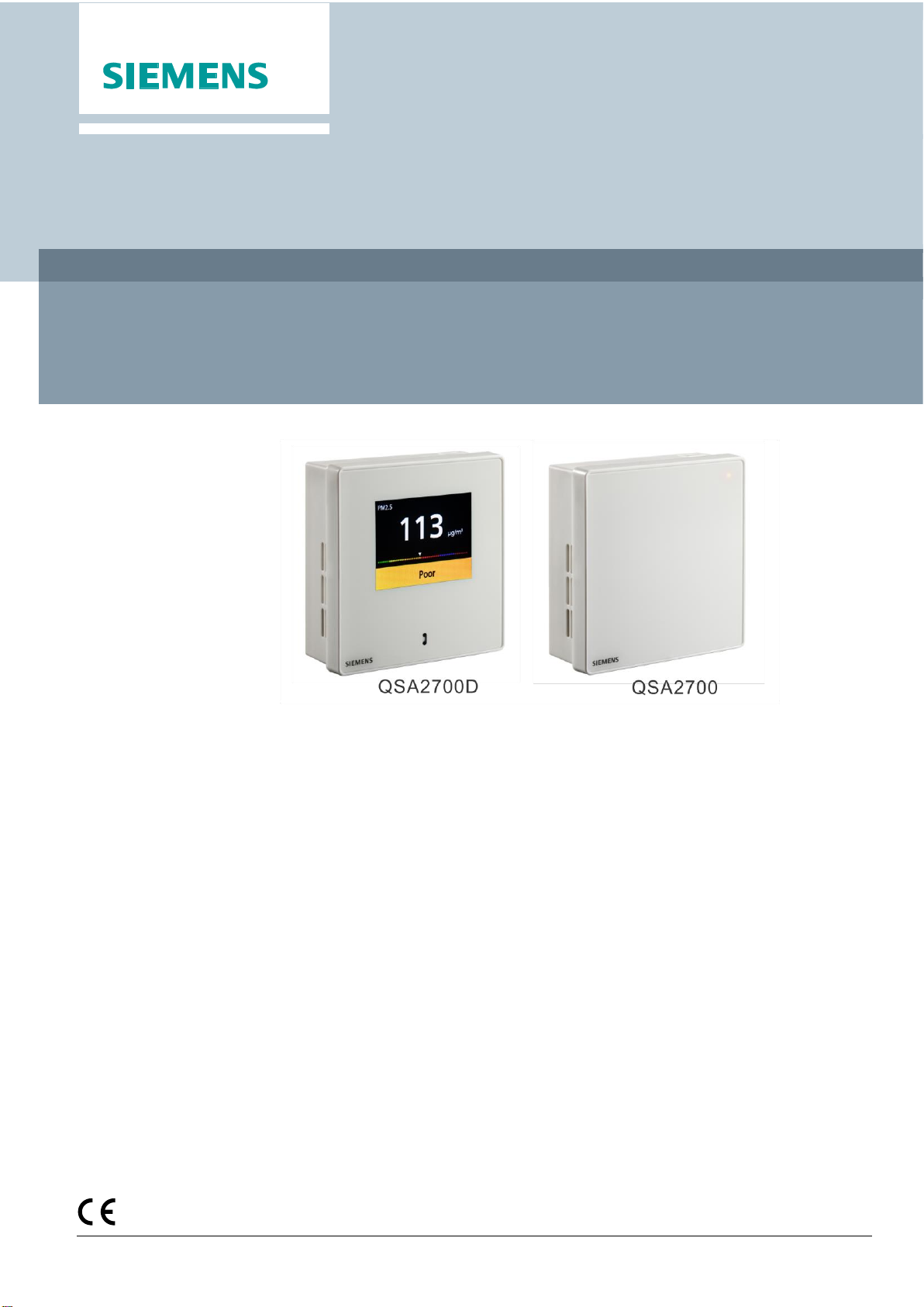
Siemens QSA2700D User manual
Other Siemens Accessories manuals

Siemens
Siemens HL 3000 User manual

Siemens
Siemens QPM11 Series User manual

Siemens
Siemens SITRANS LR 400 Guide

Siemens
Siemens WiPS-200 Series User manual

Siemens
Siemens 3VL9400-4PJ00 User manual

Siemens
Siemens QGO21 Series Operator's manual

Siemens
Siemens Simatic RF382R Scanmode User manual

Siemens
Siemens Desigo QMX3.P44 User manual

Siemens
Siemens 3200 Series User manual

Siemens
Siemens SIWAREX JB Administrator guide

Siemens
Siemens SIMATIC RF640A User manual

Siemens
Siemens SENTRON VL Series User manual

Siemens
Siemens QBM3700 Series User manual

Siemens
Siemens 6DR4004-6NN Series User manual

Siemens
Siemens HC15 User manual

Siemens
Siemens QFM2100 Service manual

Siemens
Siemens 3VL9500 - 4PA30 User manual

Siemens
Siemens MC35 Terminal Setup guide

Siemens
Siemens Milltronics Millpulse 600 User manual

Siemens
Siemens SIMATIC VS130-2vcr User manual