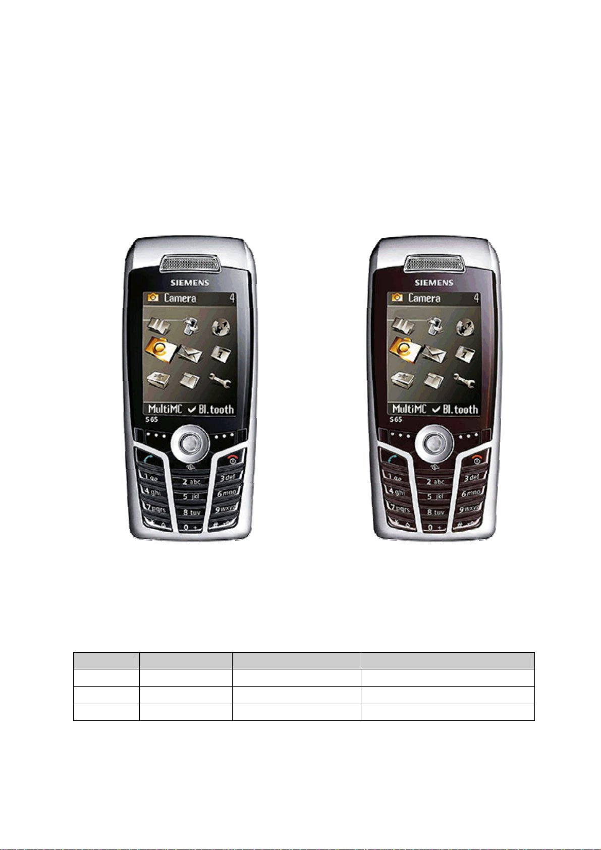
Siemens S65 Setup guide

Company Confidential s Com
Copyright 2004© Siemens AG
Page 1of 15
Service Repair Documentation
Level 2.5 light - S65
Service Repair Documentation
Level 2.5 light - S65
Release Date Department Notes to change
1.0 04.08.2004 ICM MP CCQ GRM T New document
1.1 25.11.2004 ICM MP CCQ GRM T MMC Melting Problem
1.2 12.01.2005 COM MD CC GRM T SIM Card Reader Add On

Company Confidential s Com
Copyright 2004© Siemens AG
Page 2of 15
Service Repair Documentation
Level 2.5 light - S65
Introduction
This Service Repair Documentation is intended to carry out repairs on Siemens repair level
2.5 light. The described failures shall be repaired in Siemens authorized local workshops
only,
The level 2.5 (former Level 2.5e) partners are obliged to repair level 2 classified boards, up
to their repair level, under consideration of the information given by level 2.5 (former level
2.5e) repair instruction.
All repairs have to be carried out in an ESD protected environment and with ESD protected
equipment/tools. For all activities the international ESD regulations have to be considered.
Assembling/disassembling has to be done according to the latest S65 Level 2 repair
documentation. It has to be ensured that every repaired mobile Phone is checked according
to the latest released General Test Instruction document (both documents are available in
the Technical Support section of the C-market).
Check at least weekly C-market for updates and consider all S65 related Customer Care
Information
CX65 Partnumber on IMEI label: S30880-S7400-#xxx
, while # may be any letter (A-Z) and xxx may be any number from 100, 101, 102....
Scrap Handling: All Scrap information given in this manual are related to the
SCRAP-Rules and instructions.
If you have any questions regarding the repair procedures or technical questions spare not
hesitate to contact our technical support team in Kamp-Lintfort, Germany:
Tel.: +49 2842 95 4666
Fax: +49 2842 95 4302

Company Confidential s Com
Copyright 2004© Siemens AG
Page 3of 15
Service Repair Documentation
Level 2.5 light - S65
Table of Content
1S65 board layout ...........................................................................................................................4
2Connector SIM Card Reader.........................................................................................................5
3Connector IO Jack.........................................................................................................................6
4Connector Board to Board.............................................................................................................8
5Connector Battery .........................................................................................................................9
6Connector MMC ..........................................................................................................................10
7Connector RF..............................................................................................................................11
8Connector Camera......................................................................................................................12
9Connector Display.......................................................................................................................13
10 IRDA.........................................................................................................................................14
11 JOYSTICK................................................................................................................................15

Company Confidential s Com
Copyright 2004© Siemens AG
Page 4of 15
Service Repair Documentation
Level 2.5 light - S65
1 S65 board layout
Jigs, Tools and Working materials for all described repairs:
-hot air blower
-soldering gun
-tweezers
-flux
-solder

Company Confidential s Com
Copyright 2004© Siemens AG
Page 5of 15
Service Repair Documentation
Level 2.5 light - S65
2 Connector SIM Card Reader
Fault Symptoms
Customer: GRT:
Handset does not accept SIM card SIM Card Problems
Connector SIM Card Reader
Use soldering iron to remove defective component. Avoid excessive heat! Watch surrounding components!
Resolder new component afterwards.
E-commerce order number: L36334-Z97-C337
Soldering temperature: 240 - 255°C
IRIS Diagnose Code: 43300 Interface/SIM Cardreader/Mechanical Damage
Surrounded Components
R1614 Resistor Res_Type8 L36842-C472-J
C1605 Capacitor Cap_Type3 L36853-C6224-M6
Z1601 Filter L50620-U6056-D670

Company Confidential s Com
Copyright 2004© Siemens AG
Page 6of 15
Service Repair Documentation
Level 2.5 light - S65
Connector IO Jack
Fault Symptoms
Customer: GRT:
Charging Problems No connection to GRT
Problems with external loudspeaker or microphone when using a car kit Tbd.
Problems with accessories connected at the IO connector
Connector IO Jack
Use soldering iron to remove defective component. Avoid excessive heat! Watch surrounding components!
Resolder new component afterwards.
E-commerce order number: L36334-Z93-C303
Soldering temperature: 240 - 255°C
IRIS Diagnose Code: 46100 Interface/Charging Connector/Mechanical Damage
47300 Interface/Data Interface/Mechanical Damage
4B100 Interface/Headset Connector/Mechanical Damage

Company Confidential s Com
Copyright 2004© Siemens AG
Page 7of 15
Service Repair Documentation
Level 2.5 light - S65
Important additional soldering hints
The MMC Reader is located on the opposite of the SLIM-Lumberg connector.
Therefore the risk to damage the plastic material of this MMC-Reader is
potentially high if excessive heat is used while removal or soldering of the
SLIM-Lumberg connector.
Please follow this instructions:
a) Remove the SLIM-Lumberg connector with a soldering iron and Desolder
Wick
b) Clean the Pads afterwards
c) Solder the new connecter by using soldering iron under consideration of
the max. allowed temperature range.
Samples of critical area:
Lock mechanism damaged Lock mechanism OK

Company Confidential s Com
Copyright 2004© Siemens AG
Page 8of 15
Service Repair Documentation
Level 2.5 light - S65
3 Connector Board to Board
Fault Symptoms
Customer: GRT:
Keyboard malfunction Keyboard malfunction
Keypad illumination does not work Tbd.
Connector Board to Board
Use hot air blower to remove defective component. Avoid excessive heat! Watch surrounding components!
Resolder new component afterwards.
E-commerce order number: L36334-Z97-C346
Soldering temperature: 240 - 255°C
IRIS Diagnose Code: 32100 Keys / Main / No Function
32200 Keys / Main / Reduced Functionality
36000 Keys / Illumination

Company Confidential s Com
Copyright 2004© Siemens AG
Page 9of 15
Service Repair Documentation
Level 2.5 light - S65
4 Connector Battery
Fault Symptoms
Customer: GRT:
Mobile does not switch on No connection to GRT
Connector BATTERY
Use hot air blower to remove defective component. Avoid excessive heat! Watch surrounding components!
Resolder new component afterwards.
E-commerce order number: L36334-Z97-C213
Soldering temperature: 240 - 255°C
IRIS Diagnose Code: 13000 Battery/Mechanical Damage

Company Confidential s Com
Copyright 2004© Siemens AG
Page 10 of 15
Service Repair Documentation
Level 2.5 light - S65
5 Connector MMC
Fault Symptoms
Customer: GRT:
MMC malfunction Tbd.
Connector MMC
Use soldering iron to remove defective component. Avoid excessive heat! Watch surrounding components!
Resolder new component afterwards.
E-commerce order number: L36334-Z97-C342
Soldering temperature: 240 - 255°C
IRIS Diagnose Code: B1120 Accessories / Memory / MMC / Defect
Attention: Avoid excessive heat in order not to damage the plastic material of the
connector (see problem SLIM-Lumberg connector)

Company Confidential s Com
Copyright 2004© Siemens AG
Page 11 of 15
Service Repair Documentation
Level 2.5 light - S65
6 Connector RF
Fault Symptoms
Customer: GRT:
Network search Failure by TX/RX measurements
No location update possible No location update possible
Connector RF
Use hot air blower to remove defective component. Avoid excessive heat! Watch surrounding components!
Resolder new component afterwards.
E-commerce order number: L36334-Z93-C297
Soldering temperature: 240 - 255°C
IRIS Diagnose Code:
81100 Radio / No Contact / Int. Antenna 81200 Radio / No Contact / Ext. Antenna
82100 Radio / Low Receiving Signal / Int. Antenna 82200 Radio / Low Receiving Signal / Ext. Antenna
83100 Radio / Dropped Calls / Int. Antenna 83200 Radio / Dropped Calls / Ext. Antenna
84100 Radio / Call Setup / Int. Antenna 84200 Radio / Call Setup / Ext. Antenna

Company Confidential s Com
Copyright 2004© Siemens AG
Page 12 of 15
Service Repair Documentation
Level 2.5 light - S65
7 Connector Camera
Fault Symptoms
Customer: GRT:
Camera malfunction Tbd.
Connector CAMERA
Use hot air blower to remove defective component. Avoid excessive heat! Watch surrounding components!
Resolder new component afterwards.
E-commerce order number: L36197-F5008-F341
Soldering temperature: 240 - 255°C
IRIS Diagnose Code: BA000 Accessories / Camera

Company Confidential s Com
Copyright 2004© Siemens AG
Page 13 of 15
Service Repair Documentation
Level 2.5 light - S65
8 Connector Display
Fault Symptoms
Customer: GRT:
Display problems, like missing lines or columns on
the LCD or display contrast problems or illumination
problems
Display problems
Connector DISPLAY
Use hot air blower to remove defective component. Avoid excessive heat! Watch surrounding components!
Resolder new component afterwards.
E-commerce order number: L36334-Z97-C205
Soldering temperature: 240 - 255°C
IRIS Diagnose Code: 21000 Display / Performance
22000 Display / Background Illumination

Company Confidential s Com
Copyright 2004© Siemens AG
Page 14 of 15
Service Repair Documentation
Level 2.5 light - S65
9 IRDA
Fault Symptoms
Customer: GRT:
No infrared connection possible Tbd.
IRDA
Use hot air blower to remove defective component. Avoid excessive heat! Watch surrounding components!
Resolder new component afterwards.
E-commerce order number: L36810-U6130-D670
Soldering temperature: 240 - 255°C
IRIS Diagnose Code: 41100 Interfaces / IRDA / No Function
41300 Interfaces / IRDA / Mechanical Damage

Company Confidential s Com
Copyright 2004© Siemens AG
Page 15 of 15
Service Repair Documentation
Level 2.5 light - S65
10 JOYSTICK
Fault Symptoms
Customer: GRT:
Joystick malfunction Tbd.
Joystick
Use hot air blower to remove defective component. Avoid excessive heat! Watch surrounding components!
Resolder new component afterwards.
E-commerce order number: L36315-Z77-C218
Soldering temperature: 240 - 255°C
IRIS Diagnose Code: 32100 Keys / Main / No Function
32200 Keys / Main / Reduced Functionality
Other manuals for S65
4
Table of contents
Other Siemens Cell Phone manuals

Siemens
Siemens S40 User manual

Siemens
Siemens S75 Setup guide

Siemens
Siemens SL10 User manual

Siemens
Siemens S65 User manual

Siemens
Siemens C70 User manual

Siemens
Siemens XELIBRI X8 User manual

Siemens
Siemens AF51 User manual

Siemens
Siemens EF81 User manual

Siemens
Siemens C62 User manual

Siemens
Siemens C81 User manual

Siemens
Siemens E71 User manual

Siemens
Siemens SL65 Setup guide

Siemens
Siemens S2588 User manual

Siemens
Siemens M35i User manual

Siemens
Siemens S6 GSM User manual

Siemens
Siemens Gigaset C45 Operator's manual

Siemens
Siemens AL21 User manual

Siemens
Siemens Gigaset SL400 User manual

Siemens
Siemens C75 User manual

Siemens
Siemens S42 User manual