Siemens DESIGO RXZ90.1 User manual

CA2N1644en_05
02.08.2010 Building Technologies
1644
DESIGO™ RX
Receiver with
PPS2 interface
RXZ90.1
for use in conjunction with wireless room units QAX90.1/ QAX91.1, with
– devices of the ranges DESIGO RXC, RXB, RXL, and RXA (PPS2)
– DESIGO PX Automation stations
– devices with a PPS2 or PPS interface
•Wireless acquisition of room temperature and setpoint adjustments
•For use only in conjunction with the QAX90.1/QAX91.1 wireless room units
(data sheet CA2N1643)
•Determines the average room temperature from several room units
•PPS2 interface to controller, may be changed to PPS
•Socket for commissioning and service tool, diagnostic plug or service terminal
Use
The RXZ90.1 is used for wireless reception of the room temperature (from the
QAX90.1) and the room temperature setpoint (from the QAX91.1), and for transmission
of this information to a room controller. Wireless range indoors: approx. 30m.
Types
RXZ90.1 Receiver with PPS2 interface

2 / 10
Siemens RXZ90.1 – Receiver with PPS2 interface CA2N1644en_05
Building Technologies 02.08.2010
Ordering
When ordering, please specify the quantity, product name and type code.
Example:
20 Receivers with PPS2 interface Type RXZ90.1
Compatibility
The RXZ90.1 receiver, in conjunction with wireless sensors, is suitable for use with all
devices with a PPS2 room unit interface (e.g. the DESIGO RX, DESIGO PX).
The interface may be changed to PPS by means of address plugs.
System expansion
Up to a maximum of 5 room units may be allocated to one receiver (see
Commissioning and establishing communication). If several room units are used, the
receiver determines the average of the temperature values received. The average room
temperature is then transmitted to the room controller.
In the case of room units with setpoint adjusters (QAX91.1), only one may be assigned
to each receiver. Other room units with setpoint adjusters are treated as QAX90.1 units
(room temperature only).
QAX91.1
QAX90.1
QAX90.1
RXZ90.1
QAX90.1
QAX90.1
00481 A
868 MHz
Design
The receiver is designed for mounting on walls or ceilings, or for installation in a flush
mounting box. The cables can be connected from the rear, top or bottom after breaking
out the perforated cable entry guide.
Basically the unit comprises the housing and the mounting plate. These can be
snapped together and apart.
The housing accommodates a printed circuit board and a tool socket (RJ45).
The housing and mounting plate are plastic.

3 / 10
Siemens RXZ90.1 – Receiver with PPS2 interface CA2N1644en_05
Building Technologies 02.08.2010
Mounting plate
Housing
00477
RJ45 socket on base of unit for:
•RXT10 commissioning and
service tool
•RXT20.1 service terminal
•Diagnostic plug, with button for
LONWORKS® registration
80084
1644Z11
PPS2
Jumper
Address
PPS
Jumper
Address
*
Address plugs inside the housing
They allow setting the protocol (PPS or
PPS2), as well as the address in cases
where several room units are connected
to one controller.
* Factory setting: PPS2 with address 1.
IMPORTANT: DESIGO PX auto-
mation stations only support PPS2
address 1 of the RXZ90.1.
Disposal
The device is classified as waste electronic equipment in terms of the European
Directive 2002/96/EC (WEEE) and should not be disposed of as unsorted municipal
waste.
The relevant national legal rules are to be adhered to.
Regarding disposal, use the systems setup for collecting electronic waste.
Observe all local and applicable laws.
Engineering notes
•The receiver receives its power via the PPS2 interface
•Receiver range: approx. 30 m, and up to 100 m in the open. The range can vary
widely. Room topologies and building materials (metal, concrete etc.) reduce or alter
the range significantly.
•To ensure good wireless communication with the room units, avoid metal obstacles
in the wireless field.
Avoid mounting the unit on or behind a metal cover!
•The unit must be mounted at least 1 metre from the transmitter
•An error signal "sensor short circuit" is transmitted after 3 years of uninterrupted
operation (battery monitoring feature) The batteries of all room units must then be
replaced.
N.B.: The plant documentation must contain a note to this effect!
The device is NOT equipped with address plugs. The address is 1.
Address plug
STOP
Note!

4 / 10
Siemens RXZ90.1 – Receiver with PPS2 interface CA2N1644en_05
Building Technologies 02.08.2010
Mounting instructions
•The receiver is suitable for mounting on walls or ceilings, and for installation in a
flush mounting box
•An elevated position, or mounting on the same storey as the room unit(s) can extend
the wireless range
•Depending on the materials used for the ceiling, the receiver may be concealed in
the ceiling void
(note that metal must be avoided)
•The admissible ambient conditions must be observed
•The mounting instructions and a drilling template are printed on the device packa-
ging
•A set of fixing accessories is enclosed with the room unit
•Do not mount on a metal surface
•Do not install behind a cover or a metal grid which impedes wireless communication
•The unit must be mounted at least 1 metre from the transmitter
Response on start-up (PPS2)
After an interrupt of the PPS2 interface the communication will only be re-established
when the connected controller polls the PPS2 addresses. The duration of the
corresponding cycle is:
RXA: 10 sec; RXB, RXL and RXC: 3 min; PX: 30 sec.
Commissioning and establishing wireless communication
Please do not make any adjustments without a careful reading of the following
commissioning notes.
•The unit(s) must be mounted at least 1 metre from the receiver
•Where there is more than one receiver in the same building, communication must be
established with each receiver separately, after a time delay. This is because
commissioning signals can be received from adjacent rooms, or even from
neighbouring buildings during the commissioning process.
Communication between the wireless room unit and the receiver can be established
either before or after installation. Checking the wireless communication (see below)
only makes sense when all the devices are mounted.
PLEASE FOLLOW THE INSTRUCTIONS EXACTLY IN THE SEQUENCE SHOWN:
1. Snap-mount the RXZ90.1 receiver on the mounting plate (power ON: the receiver
goes into "Installation" mode).
2. Insert batteries in all the allocated wireless room units (max. 5) or remove the
isolating strip from the batteries already inserted. (power ON: the room unit
transmits its unique ID to the receiver).
3. You can establish communication with the next receiver as soon as the 4-minute
"Installation mode" has expired in all the room units.
STOP
Caution!
STOP
Caution!
Establishing
communication
for the first time

5 / 10
Siemens RXZ90.1 – Receiver with PPS2 interface CA2N1644en_05
Building Technologies 02.08.2010
Brief pressure (<1 s) on the button adjacent to the battery holder of the room unit allows
you to check the wireless link with the receiver. After receiving this signal, the receiver
will close the PPS2 interface for 1.5 s. This briefly extinguishes the display on the
connected RXT20.1 service terminal (or the green LED on the diagnostic plug, see
Diagnostics, below). If there is no wireless link with the receiver, the display on the
service terminal (or the green LED) will not be extinguished.
Pressing the button on the room unit causes the room controller to send its Neuron ID
in the same way as for registration on the LONWORKS® bus. However, when checking
the wireless communication, we are not interested in the Neuron ID, but in observing
whether the controller reacts to the wireless signal.
Additional functions for establishing communication
Sustained pressure (>5s) on the button of the room unit to be removed.
The receiver will delete only this room unit from its device list.
Caution: Wait 4 minutes before changing any further links.
Sustained pressure (>5s) on the button of the room unit to be replaced.
The receiver will delete this room unit from its device list and then switch to installation
mode.
Insert batteries in the replacement unit(s); these will switch to installation mode.
The receiver recognises all newly connected room units and adds these to its device
list.
Caution: Wait 4 minutes before changing any further links.
Sustained pressure (>5s) on the button of one of the existing room units.
The receiver will delete this room unit from its device list and then switch to installation
mode.
Insert the batteries in all the additional devices to be installed (or remove insulating
strip); the devices will switch to installation mode.
The receiver recognises all newly connected room units and adds these to its device
list.
The room unit on which the button has been pressed, is deleted from the device list and
therefore has to be reconnected. To bring it off load and set it to installation mode,
remove the batteries for at least 30s.
Caution: Wait 4 minutes before changing any further links.
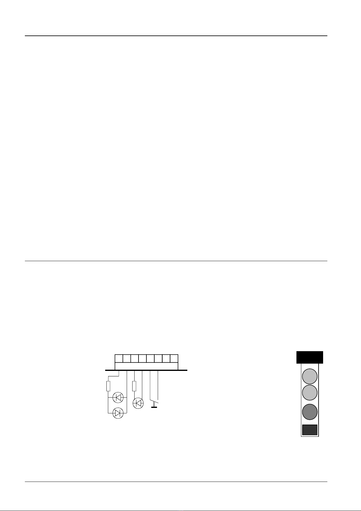
For this purpose you need a special diagnostic plug (see Diagnostics, below). Insert it
and press the button on the plug for >5s. This will delete the entire device list from the
receiver and then bring it to the "Normal mode" with an empty device list.
To re-commission it, shortly bring the receiver off-load.
Then follow the procedure under Establishing communication for the first time.
Checking the wireless
communication
Remark for RXC
Cancelling the link with
a room unit
Replacing room units
(replacement units)
Connecting additional
room units to an
existing receiver
Deleting all links with a
receiver
.
.

6 / 10
Siemens RXZ90.1 – Receiver with PPS2 interface CA2N1644en_05
Building Technologies 02.08.2010
Additional notes:
•The room unit starts in installation mode each time batteries are inserted (after min.
30s off load)
•When there are no room units in its device list, the receiver starts in installation mode
when the power supply is connected. It scans for installation signals for 3 ½ minutes,
and identifies all room units in installation mode within its receiver range
•The first 5 room units identified are entered in the device list of the receiver
•For each receiver, a delay must precede the process of establishing communication,
as the receiver can also pick up signals from other room units in the vicinity
Wait at least 4 minutes between each new installation sequence
•A Receiver with at least one room unit in its device list will not switch to installation
mode after a power failure, but continue normal operation with the associated room
units.
•Connecting the receiver to the power supply (power ON) when the device list is
empty (snap-mount RXZ90.1 receiver on mounting plate)
•Connecting the controller to the power supply, when the receiver is connected to
the controller and its device list is empty
•With fewer than 5 room units registered, connecting the diagnostic plug to the
receiver and pressing the button briefly ( < 1s)
•Plugging the RXT20.1 service terminal into the receiver with an empty device list,
and pressing the service pin on the RXT20.1 >4s
•Sustained pressure (>5s) on the button of an existing room unit.The receiver will
delete this room unit from its device list and then switch to installation mode
Diagnostics and the diagnostic plug
The process of establishing communication (receiver status) can be monitored by
connecting the diagnostic plug to the receiver.
The plug can be assembled in-house or ordered from your national Landis & Staefa
office. It is an aid for the service staff and cannot be purchased normally.
•Connections 3 and 4 are short-circuited by a pushbutton
•Connections 5 (+) and 6 (–) are used to operate a red LED
•Connections 7 and 8 are used to operate the green LEDs
(One of the two green LEDs will light up, depending on the polarity of the bus power
supply)
Tool socket
Series resistors
R = 11.2k
43217865
00495
LEDs (2mA) Button
2x green 1x red
RJ45 telephone-type socket
Cable (8-wire)
Green LED (<2mA)
Green LED (Optional,
lights up in event of
incorrect polarity)
Red LED
Pushbutton
Installation mode
Different ways of setting
the receiver to installa-
tion mode

7 / 10
Siemens RXZ90.1 – Receiver with PPS2 interface CA2N1644en_05
Building Technologies 02.08.2010
Status Red LED signals
Installation mode Permanently ON
Normal mode
Receiver's device list is empty
Rapid flashing
(approx. 5 times per s)
Normal mode
Receiver's device list not empty
1 room unit: 1 flash / 5 s pause
2 room units: 2 flashes / 5 s pause
3 room units: 3 flashes / 5 s pause
4 room units: 4 flashes / 5 s pause
5 room units: 5 flashes / 5 s pause
Normal mode
Receiver's device list not empty and
PPS2 communication not working
Flashes more slowly (approx. once/s)
(e.g. during initialisation of the
controller after POWER ON)
Status Green LED signals
PPS2 power supply ON ON continuously
PPS2 short circuit OFF
Pushbutton Action
Brief pressure <1s Sets receiver to installation mode if
fewer than 5 room units in device list
Sustained pressure >5s Deletes the device list from the recei-
ver and then brings it to the "Normal
mode" with an empty device list.

8 / 10
Siemens RXZ90.1 – Receiver with PPS2 interface CA2N1644en_05
Building Technologies 02.08.2010
Technical data
Power supply Operating voltage range SELV / PELV DC 12 ... 15 V
The device receives its power from the connected controller via PPS2
Power consumption S1 (from controller) Max. 0.12 VA
Interfaces Receiver – controller PPS2 (point-to-point interface)
Baud rate 4.8 kbit/s
Protocol may be changed to PPS
Wireless room unit – Receiver Uni-directional
Frequency band 868 MHz Operating frequency 868.95 MHz
Baud rate 19.2kbit/s
Modulation BFSK
Channel coding NRZ / BCH
Transmitter power (ERP) 1 mW (0 dBm)
Range inside building Approx. 30 m
(depending on building permeability)
Establishing a connection
(configuration)
Pushbutton method
Connection test (registration on
LONWORKS®)
Service pin (brief pressure of button
on QAX9x.1)
Cable connections Connection terminals (screw terminals) Stranded or solid conductors,
0.8 x 2.5 mm2
Single cable length controller – Room unit See Installation guidelines:
DESIGO RXC: CA110334,
DESIGO RXB & RXL: CM110891
DESIGO RXA: CA2Z3884
DESIGO PX: CA110396
2-core or 4-core, twisted pairs,
unscreened
Tool connecting cable Made up in-house, max. 3 m
Housing protection standard Protection standard to EN 60529 IP 30
Protection class Insulation protection class III
Ambient conditions Ambient conditions to IEC721 Operation: Transport:
Environmental conditions Class 3K5 Class 2K3
Temperature 0 ... 50 °C – 25 ... 70 °C
Humidity < 85 rh < 95 rh
Mechanical conditions Class 3M2 Class 2M2
Standards and directives conformity
Electromagnetic compatibility 2004/108/EC
Low Voltage Directive 2006/95/EC
Radio Equipment and
Telecommunication Terminal Equipment
1999/5/EC
Electromagnetic compatibility
Emission (residential) EN 61000-6-3
Product safety EN 60950-1
Product safety (EMF) EN 50371
ERM (Short range devices) EN 300 220-2
EN 301 489-3
C-Tick conformity (EMC) AS/NZS 61000-6-3
Dimensions See “Dimensions”
Colour Front plate NCS S 0502-G
≈RAL 9003 signal white
Housing base and mounting plate RAL 7035 light grey
Weight Excluding packaging 0.13 kg

9 / 10
Siemens RXZ90.1 – Receiver with PPS2 interface CA2N1644en_05
Building Technologies 02.08.2010
Connection terminals
Connecting a commissioning and service tool or service terminal to the tool socket on
the receiver provides access to the connected room controllers.
The bus cable (terminals 3 and 4) is looped through to the tool socket (pins 1 and 2) for
this purpose. The bus cable is not affected by the receiver.
The PPS2 interface is also routed to the tool socket, enabling a service terminal to be
connected.
87654321
C–
C+
CP–
CP+
80085
PPS2 interface, power supply
CP+ 1 Device power supply, PPS2 data (positive)
CP– 2 Device power supply, PPS2 data (negative)
Bus connection (looped to tool socket)
C+ 3 with LONWORKS® bus (DESIGO RXC): CLA
C– 4 with LONWORKS® bus (DESIGO RXC): CLB
5...8 Not used
Tool socket
Standard RJ45 tool socket
Communication Diagnostic plug
1
3206Z01
2345678
1 with LONWORKS® bus (DESIGO RXC): CLA
2 with LONWORKS® bus (DESIGO RXC): CLB
3
4
5
6
7 CP+ PPS2 data
8 CP– PPS2 data
Button for installation
Red LED +
Red LED –
Green LED +
Green LED –
Connection diagrams (example: RXC)
The following example shows the room unit connected to a DESIGO RXC room
controller:
1644A01
PPS2
Tool
A
R1
B
4321
4321
C–
C+
CP–
CP+
N1
CP+
CP–
CLA
CLB
PPS2
7865
C
LonWorks® Bus
Twisted pair
R1 RXZ90.1 receiver
N1 RXC… room controller
A Connection for RXT10.1 commissioning and service tool
B Connection for RXT20.1 service terminal with PPS2 interface
C Connection for diagnostic plug

10 / 10
Siemens RXZ90.1 – Receiver with PPS2 interface CA2N1644en_05
Building Technologies 02.08.2010
Dimensions
9,5
32
36
4,2
60
00496
90
100
56
60
56
2000 - 2010 Siemens Switzerland Ltd Sub
j
ect to chan
g
e
Other manuals for DESIGO RXZ90.1
1
Table of contents
Other Siemens Receiver manuals

Siemens
Siemens RDD100.1RF User manual

Siemens
Siemens DESIGO RXZ90.1 User manual

Siemens
Siemens easyTek User manual

Siemens
Siemens SICAM FCM User manual

Siemens
Siemens RCR100FPRF User manual

Siemens
Siemens RCR114.1 User manual

Siemens
Siemens SENTRON VL Series User manual

Siemens
Siemens WTX16.GSM User manual

Siemens
Siemens RCR114.1 User manual

Siemens
Siemens RK 761 User manual