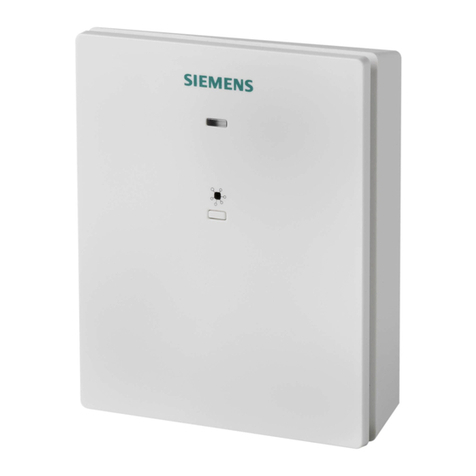
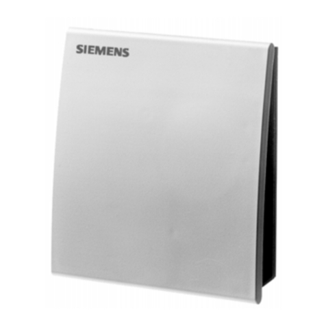
Siemens RCR114.1 User manual

A6V11562464_en
--_a
Smart Infrastructure
2019-09-19
Smart Thermostat Receiver
RCR114.1
Smart Thermostat Receiver works with RDS110.R.
●
Mains-powered receiver AC 230 V
●
Configurable via DIP switch
●
Communicate with RDS110.R via Thread network
●
Online firmware upgrade via Thread network

2
Smart Infrastructure
A6V11562464_en--_a
2019-09-19
Use
The RCR114.1 works as a router-eligible end device (REED) in the network created by
RDS110.R.
Functions
RCR114.1 can be configured via the DIP switch on its backside to be a relay box or wireless
repeater.
Relay box
RCR114.1 is installed within the network coverage of RDS110.R.
Wireless repeater

3
Smart Infrastructure
A6V11562464_en--_a
2019-09-19
If RCR114.1 is installed too far away from RDS110.R, another RCR114.1 (works as a
wireless repeater) should be added in between to extend the network coverage. See
Mounting [➙ 4] for details.
Note:
1. DIP switch 2 is reserved for internal use only.
2. One RDS110.R can pair up with at most 3 repeaters and 6 relays to extend the network
coverage.
3. You cannot mannually turn ON / OFF a RCR114.1.
Mechanical design
The RCR114.1 consists of 2 parts:
●Plastic housing which accommodates the electronics
●Mounting plate
Operation and settings
1 LED for indication of operating status
2 Button for user operation
Type summary
Type
Stock number
Description
RCR114.1 S55772-T104 Smart Thermostat Receiver
Ordering
When ordering, indicate product number, stock number and description.

4
Smart Infrastructure
A6V11562464_en--_a
2019-09-19
Equipment combinations
Room thermostats
Product number
Stock number
Description
RDS110.R S55772-T103 Smart Thermostat Wireless
Wireless actuator
Product number
Stock number
Description
SSA911.01TH S55181-A101 Radiator valve act. THREAD
Note: the RDS110.R cannot control a relay box and a valve actuator in parallel.
Wireless receiver
Product number
Stock number
Description
RCR114.1 S55772-T104 Smart Thermostat Receiver
Product documentation
Topic
Title
Document ID
Mounting and installation Mounting instructions A6V11562443
Startup wizard Quick guide A6V11562447
CE declaration A6V11849464
Product environmental declaration A6V11806767
Related documents such as environmental declarations, CE declarations, etc., can be
downloaded at: http://siemens.com/bt/download.
Notes
Security
CAUTION
National safety regulations
Failure to comply with national safety regulations may result in personal injury and property
damage.
●Observe national provisions and comply with the appropriate safety regulations.
Mounting
●The device is suitable for wall mounting and surface mounting.
●Enclose the conductors in a conduit when surface mounting.
●Reserve sufficient free space for ventilation (refer to the following picture).
●Avoid direct solar radiation.
●Adhere to allowed ambient conditions.
●Install the receiver close to RDS110.R if possible. The communication range in a building
is typically 60 m without any blockades. Please note that the range can vary as walls,
floors, wireless interference and other factors may reduce the signal strength.

5
Smart Infrastructure
A6V11562464_en--_a
2019-09-19
●Choose the location to ensure largely interference-free reception. When mounting the
receiver, observe the following:
– Do not mount in a control panel
– Do not mount on metallic surfaces
– Do not mount near 2.4 GHz wireless electronic devices such as PCs, WiFi routers,
microwaves, etc.
– Do not mount near constructional elements with fine metal or large metallic
structures such as a distribution box
Wiring
●The AC 230 V mains supply line must have an external circuit breaker with a rated
current of no more than 10 A.
●Ensure that wiring, protection and earthing comply with local regulations.
●Adapt the line diameters as per local regulations to the rated value of the installed
overcurrent protection device.
●Disconnect from power supply before removing the unit from its mounting plate.
●Make sure the receiver is not connected to power during wiring.
Commissioning
LED indication on RCR114.1
RCR114.1 has one LED to indicate its status.
Device status
LED status
Idle Solid yellow
Connecting to RDS110.R Flashing green
Successful connection Solid green
Thread network works, but communication with RDS110.R
failed1)
Flashing red
Thread network failure2) Solid red
Factory reset Alternating red and green
1. Reconnection is performed automatically or manually.
2. Reconnection can only be performed manually.
Manual network reconnection
1. Check whether RDS110.R is powered on and in normal operation.
2. If the reconnection still fails, delete RCR114.1 in the device list of RDS110.R, then long
press button on RCR114.1 for 8 seconds and re-add RCR114.1 to the device list.

6
Smart Infrastructure
A6V11562464_en--_a
2019-09-19
Operation
RCR114.1 has one physical button for user operation.
Operation
Device action
Short press (if idle) Join network and attempt binding
Short press (if connected) Device identification
Short press (in other status) No action
Long press Factory reset to idle
Maintenance
The receiver is designed for maintenance-free operation.
Disposal
The device is considered an electronic device for disposal in accordance
with the European Guidelines and may not be disposed of as domestic
garbage.
●Dispose of the device through channels provided for this purpose.
●Comply with all local and currently applicable laws and regulations.
Warranty
Technical data on specific applications are valid only together with Siemens products listed
under Equipment combinations. Siemens rejects any and all warranties in the event that
third-party products are used.
Radio equipment directive
The equipment is using harmonized frequency in Europe, and complies with the Radio
Equipment Directive (2014/53/EU, formerly 1999/5/EC).

7
Smart Infrastructure
A6V11562464_en--_a
2019-09-19
Technical data
Power supply
Operating voltage AC 230 V (+10/-15%)
Frequency 48…63 Hz
Power consumption 5 VA
Radio parameters
Frequency band 2.4…2.4835 GHz
Maximum radio-frequency power 15 dBm
Thread standard IEEE 802.15.4
Thread channel 11-26
Switching capacity of relays
Voltage AC 24…230 V
Current Q11- Q12 Max. 5 A
Q11- Q14 Max. 8 (2) A
Q21- Q22 Max. 5 A
Q21- Q24 Max. 8 (2) A
WARNING
No internal fuse.
External preliminary protection with max. C 16 A circuit breaker in the supply lines
required under all circumstances.
External protection for incoming cable
Circuit breaker Max. 16 A
Circuit breaker tripping characteristic Type B, C or D to EN 60898 and EN 60947
Contact life at AC 230 V
At 8 A res.
Guided value:
1 x 10⁵ cycles
Insulation strength
Between relay contacts and coil
Between relay contacts (same pole)
AC 5,000 V
AC 1,000 V
Electrical connections
Connection terminals Screw terminals
For solid wires 2 x 1.5 mm2
For stranded wires 1 x 2.5 mm2(Min. 0.5 mm2)
Ambient conditions and protection classification
Safety class as per EN60730 Class II
Degree of protection of housing as per EN
60529
IP30
Classification as per EN 60730
Function of automatic control devices
Operation altitude
Degree of contamination
Overvoltage category
Type 1
< 3000 m
2
III

8
Smart Infrastructure
A6V11562464_en--_a
2019-09-19
Ambient conditions and protection classification
Climatic ambient conditions
Transport (packaged for transport) as per EN
60721-3-2
Storage as per EN 60721-3-1
Operation as per EN 60721-3-3
Transport/ Storage:
Temperature -25...60 °C (-13... 158 °F)
Air humidity 5...95% r.h. (non-condensing)
Operation:
Temperature 0...50 °C (23... 122 °F)
Air humidity 5...95% r.h. (non-condensing)
Mechanical ambient conditions
Transport as per EN 60721-3-2
Operation as per EN 60721-3-3
Class 2M2
Class 3M2
Standards, directives and approvals
EU conformity (CE) A6V11849464*)
RCM conformity A6V11231674 *)
Environmental compatibility The product environmental declaration
A6V11806767*) contains data on
environmentally compatible product design
and assessments (RoHS compliance,
materials composition, packaging,
environmental benefit, disposal).
*) The documents can be downloaded from http://siemens.com/bt/download.
General
Receiver with package, user document and accessory 262 g
Receiver 174 g
Housing: RAL9003
Diagrams
Connection terminals
Terminal
Designation
L, N Power supply, AC 230 V
Q11, Q21 Control input (com)
Q12, Q22 Control output, NC contact
Q14, Q24 Control output, NO contact
Wiring diagrams
Example 1 illustrates a convenient wiring method (AC 230 V with bridge). If the load is not
AC 230 V, refer to example 2.
9
Smart Infrastructure
A6V11562464_en--_a
2019-09-19
Example 1: Loads = AC 230 V
Example 2: Loads Y1, Y2 ≠ AC 230 V
Y1 HVAC equipment
Y2 DHW / Dehumidifier / Humidifier
KT Relay
Application examples
Applications
Gas boiler
Electric boiler
Floor heating with valve
Radiator with pump

10
Smart Infrastructure
A6V11562464_en--_a
2019-09-19
Applications
Floor heating with pump
Electric radiator
Electric floor heating
Fan with electric heating
Domestic hot water boiler
N1 RDS110.R
N2 RCR114.1
F1, F2 Limit thermostats
K1 Heat generator (e.g. boiler)
Y1 Magnetic valve
Y2 Domestic hot water boiler
Y3 Valve
M1 Circulating pump

11
Smart Infrastructure
A6V11562464_en--_a
2019-09-19
Dimensions

12
Smart Infrastructure
A6V11562464_en--_a
2019-09-19
Issued by
Siemens Switzerland Ltd
Smart Infrastructure
Global Headquarters
Theilerstrasse 1a
CH-6300 Zug
Tel. +41 58 724 2424
www.siemens.com/buildingtechnologies
© Siemens Switzerland Ltd, 2019
Technical specifications and availability subject to change without notice.
Document ID A6V11562464_en--_a
Edition 2019-09-19
Other manuals for RCR114.1
2
Table of contents
Other Siemens Receiver manuals

Siemens
Siemens SICAM FCM User manual

Siemens
Siemens DESIGO RXZ90.1 User manual

Siemens
Siemens WTX16.GSM User manual

Siemens
Siemens RCR114.1 User manual

Siemens
Siemens SENTRON VL Series User manual

Siemens
Siemens RK 761 User manual

Siemens
Siemens RCR100FPRF User manual

Siemens
Siemens DESIGO RXZ90.1 User manual

Siemens
Siemens RDD100.1RF User manual

Siemens
Siemens easyTek User manual