Siemens 7XV5451-0 A00 Series User manual

A 12/03 Repeater 820nm / 1300nm Page 3 of 32
s
Page 2 of 32 Repeater 820nm / 1300nm A 12/03
s
0General Instructions
This manual includes the information required for the normal use of the
products described therein. It is intended for technically qualified
personnel which has been specially trained or has special knowledge in
the fields of instrumentation, control, and automatic control engineering
(called automation in the following).
The knowledge and the technically correct translation of the safety
instructions and warnings included in this manual are a prerequisite for
the safe installation and commissioning, as well as for safety during
operation and maintenance, of the product described. Only qualified
personnel, as defined in the following explanation, possess the technical
knowledge required to interpret correctly and to put into action for each
individual case the safety instructions and warnings given in this
document in a general manner.
This manual is an integral part of the scope of delivery. However, it
cannottakeintoaccounteverydetailonalltypesofthedescribedproduct
and also every possible case regarding installation, operation or
maintenance.
If further information is desired or in case special problems should arise,
which are not treated adequately in this document, it is possible to
obtain additional details from the local Siemens office or from the
addresses stated in the back of this manual.
Additionally,we point outthat the contentof this productdocumentation
is not part of or modifies any previous or existing agreement, promise,
or legal relationship.
All obligations by Siemens result from the respective purchase order
whichalsoincludesthecompleteandexclusivelyvalidwarrantyprovision.
The contractual warranty regulations are neither extended nor limited
by the statements in this document.
Contents
0General Instructions ....................................................................3
1Operating Instructions ................................................................6
1.1 Scope of Application ...................................................................6
1.3 Technische Daten .........................................................................8
1.4 Description of the Functional Unit.........................................17
1.4.1 Terminal Assignment ................................................................ 17
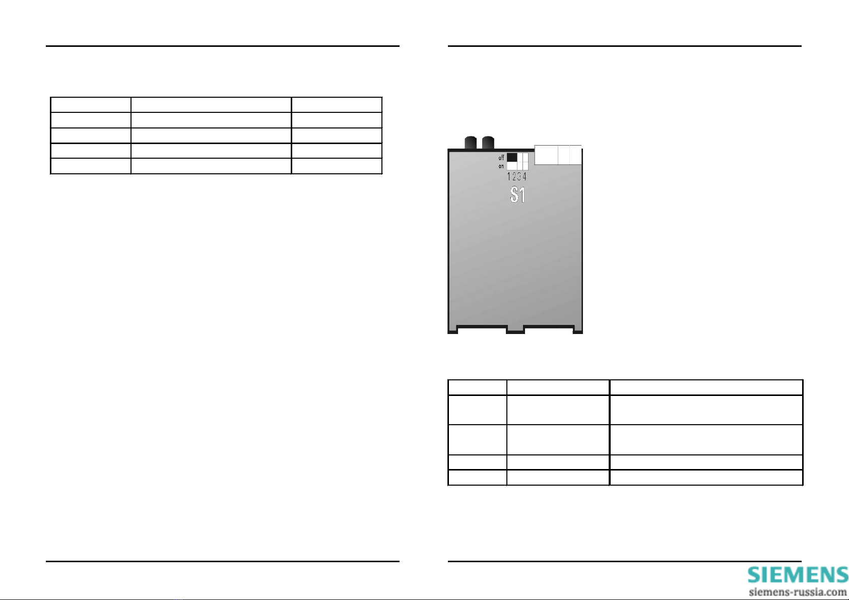
1.4.2 Switch Positions ........................................................................19
1.4.3 Applications ...............................................................................20
1.4.4 Dimension Drawings ................................................................22
1.5 Ordering Data ..............................................................................23
1.6 Mounting and Operation..........................................................23
1.7 Settings ........................................................................................27
1.8 Maintenance ................................................................................27
Figures
Abb. 1: Terminal Assignment ............................................................. 17
Abb. 2: Switch Positions .....................................................................19
Tables
Tab. 1: Terminal Assignment .............................................................18
Tab. 2: DIP-Switches S1 .....................................................................19

A 12/03 Repeater 820nm / 1300nm Page 5 of 32
s
Page 4 of 32 Repeater 820nm / 1300nm A 12/03
s
QUALIFIED PERSONNEL
Tampering with the device/system or noncompliance with the safety
notices given in this manual may cause severe bodily injury or property
damage. Therefore any interventions on the device/system may only be
performed by adequately qualified personnel.
Qualified personnel as per the safety notices given in these instructions
or on the product itself is:
•personnel involved in planning and configuration activities and
familiar with the safety concepts used in automation engineering;
•operating personnel trained for working with automation systems
and familiar with the content of this manual as far as it deals with
operational aspects;
•commissioning and service personnel having adequate training and
qualification to repair this type of automation equipment and/or
having authorization to commission, release, ground and tag
devices, systems and electrical circuits.
Explanation of symbols used:
V Read the operating instructions;
operation by qualified personnel only
Double insulation
VWarning!
When operating electrical devices, certain parts of these devices are
necessarily under dangerous tension. Therefore, noncompliance with
the safety notices may cause severe bodily injury or property damage.
Onlyadequatelyqualifiedpersonnelmayworkwith this device. Correct
and safe operation of this device requires appropriate transport,
specialized storage, installation and assembly, as well as careful
operation and maintenance. The devices are tested with AC 3.7 kV
with respect to their insulation resistance.

A 12/03 Repeater 820nm / 1300nm Page 7 of 32
s
Page 6 of 32 Repeater 820nm / 1300nm A 12/03
s
DataTransfer
The logic of the two optical interfaces is positive (Light OFF in idle
state), incoming light signals are treated as active = 1 (high). For use in
systems operating with a negative logic, the 820 nm transmitter and
the 820 nm receiver can be switched over to negative logic by means of
one integrated switch each. On delivery, the converter is set to positive
logic (Light OFF in idle state).
The 1300 nm optical interface can only operate with a negative logic
(Light ON in idle state).
Connection of the FO Channel
The FO cables are connected to the corresponding FO elements. The
connector type for the 1300 nm cable is BOFC (ST) for monomode fiber
and for the 820 nm multimodecable FSMA fiber.
1Operating Instructions
1.1 Scope of Application
The optical repeater is used for conversion of signals with a wavelength
of 820 nm to signals with a wavelength of 1300 nm and vice versa.
Operation is full-duplex.
With the optical repeater, transmission of data signals by monomode
fiber is possible up to a distance of (typically) 14km.
General Data
The optical repeater has a plastic housing that can be snapped onto a
mounting rail. The 1300 nm optical interface is equipped with BFOC
connectors.
Delivery of the 820 nm/1300 nm converter:
820 nm interface with FSMA connectors: 7XV5451-0AA00
The auxiliary power supply is fed in via two terminals. Because of its
extremely wide auxiliary voltage range (DC 24 - 250 V and AC 60 - 250
V), the converter can be connected without switchover to all common
types of station batteries and AC mains voltage supplies.
The front cover has a green LED for indication of the operating voltage
status.
The status of the internal +5V operating voltage can be checked by
means of a potential-free relay contact that is brought out to two
terminals. An open contact means that the operating voltage is o.k.
The readiness for service of the unit is indicated by means of a potential-
free signalling contact (terminals 1,2) that can be used to communicate
the following fault conditions to a control center:
•No supply voltage
Failure of internal power supply
When a fault condition is present, the contact is closed.
Attention ! In the transmission of serial protocols like
IEC 60870-5-103, IEC61850-5-101, DIGSI, Modbus, DNP3 etc.
problems appeared in a few cases. Of the use in such
applications we dissuade therefore urgently.

A 12/03 Repeater 820nm / 1300nm Page 9 of 32
s
Page 8 of 32 Repeater 820nm / 1300nm A 12/03
s
Optical 820 nm Interface
Optical inputs / outputs
FO connector
Data flow indicator
Wavelength
Data output
Sensitivity
Optical budget
Maximum distance spanned
Maximum baud rate
Minimum baud rate
1 transmitter, 1 receiver
FSMA (
plastic protective caps
)
none
820 nm
-19dBm: gradient
fiber 50/125µm
-15dBm: gradient
fiber 62,5/125µm
-30dBm
10 dB (+3 dB loss budget)
• 3 km with
62,5/125 µm gradient fiber
•In combination with
SIPROTEC systems the
distance spanned
with multimode fiber
62,5/125 µm is 1,5km
•3,5m with plastic fiber
980/1000 µm
5 MBd
9,6kBd
1.3 Technische Daten
Mechanical Design
Housing
Dimensions
Weight
Degree of protection
Housing
Terminals
Plastic, EG90
see dimensional drawings
approx. 250 g
acc. to EN60529
IP 51 plastic
IP 20
Auxiliary Power UH
Rated input voltage
- DC voltage
- AC voltage
Class of protection
Power consumption
- DC voltage
- AC voltage
DC 24 V - 250 V ± 20 %
AC 60 V - 230 V ± 20 % / 45-65 Hz
III
at UH= UHN; typical value
3 W
3.5 VA
Fault Signal Output
Connector
Test voltage
Switching voltage (rated
voltage)
Switching capacity
Switching current
Fault indicator
Measuring and control relay,
1 NC contact, potential-free
2-pole Phoenix terminal
3.7 kVeff
DC 250 V
20 W/VA
1 A permanent
Green LED: 5 V o.k.

A 12/03 Repeater 820nm / 1300nm Page 11 of 32
s
Page 10 of 32 Repeater 820nm / 1300nm A 12/03
s
Insulation Tests
EN61010
IEC 255-5: ANSI/IEEE C37.90.0
Voltage test (routine test)
- Auxiliary power to relay
Surge immunity test (type test)
VDE0435, Pt. 303
- Auxiliary power to relay
DC 5.25 kV / 1 s
(with bypass capacitors)
AC 3.7 kV / 50 Hz / 1 s
(without bypass capacitors)
3 positive and 3 negative
surges in intervals of 5 s
all circuits, Class III (not on
open contacts)
Optical 1300 nm Interface
only HCS 9/125 µm monomode
fiber
(attenuation approx. 0.5 dB/km)
Optical inputs / outputs
FO connector
Data flow indicator
Fault indicatore
Wavelength
Injective power
Sensitivity
Optical budget
Minimum distance
Maximum baud rate
Minimum baud rate
1 transmitter, 1 receiver
Delivery state:
Light OFF in idle state
Transmitter : HFBR 1315M
Receiver : HFBR 2315M
ST-plug
Yellow LED receive
Green LED: 5 V o.k.
1300 nm
min. -23 dBm = 20uW
typ. -45 dBm
min 9dB
14 km with 9/125 µm
monomode fiber
5 MBd
9,6KBd
Safety Tests
acc. to DIN EN 61010 Part 1
Overvoltage category
Pollution degree
Fire integrity class acc. to UL 94
III
2
V0

A 12/03 Repeater 820nm / 1300nm Page 13 of 32
s
Page 12 of 32 Repeater 820nm / 1300nm A 12/03
s
Radiated RF immunity,
pulse-modulated
IEC 1000-4-3
ENV 50140 / ENV50204, Class III
Immunity to fast transient bursts
IEC 1000-4-4, Class IV
IEC 255-22-4, Class IV
EN 61000-4-4, Class IV
Immunity to fast transient bursts
IEC 1000-4-4, Class III
IEC 255-22-4, Class III
EN 61000-4-4, Class III
Immunity to conducted
disturbances induced by radio
frequency fields,
amplitude-modulated
ENV 50141, Class III
Immunity to power frequency
magnetic fields
EN 61000-4-8, Class IV
10 V/m; 900 MHz; repetition
frequency 200 kHz;
ED 50 % or ED 100 %
On auxiliary power lines
4 kV; 5/50 ns; 2.5 kHz;
burst duration 15 ms
Repetition rate 300 ms;
both polarities;
Ri = 50 ohms;
test duration 1 min
On signal lines
2 kV; 5/50 ns; 5 kHz;
burst duration 15 ms
Repetition rate 300 ms;
both polarities;
Ri = 50 ohms;
test duration 1 min
10 V; 150 kHz to 80 MHz;
80% AM;
1 kHz
30 A/m, permanent; 300 A/m
during 3 s;
50 Hz
Interference Immunity Tests
IEC 255-22 (product standard)
EN 50082-2 (basic specification)
Immunity to radio-frequency
EM fields
IEC 255-22-1, Class III
VDE 0435 Part 303, Class III
Immunity to electrostatic
discharge ESD
IEC 1000-4-2, Class III
IEC 255-22-2 Class III
EN 61000-4-2, Class III
Radiated RF immunity,
unmodulated
IEC 255-22-3 Class III
Radiated RF immunity,
amplitude-modulated
IEC 1000-4-3
ENV 50140, Class III
1 MHz; 400 surges per sec.;
duration 2 s
2.5 kV longit. voltage; 1 kV
transverse voltage
4 kV contact discharge
8 kV air discharge,
both polarities; 150 pF;
Ri = 330 ohms
10 V/m; 27 MHz to 500 MHz
10 V/m; 80 MHz
to 1000 MHz;
80% AM; 1kHz
Electromagnetic Compatibility
Tests
Standard: EN 50081-1
Immunity to radio interference
voltage on lines (auxiliary power
lines only)
CISPR 22, EN 55022
DIN VDE 979 Part 22
Interference field strength
CISPR 22, EN 55022
DIN VDE 0878 Part 22
150 kHz bis 30 MHz
Limit class B
Limit class B
30 MHz to 1000 MHz
Limit class B
Limit class B

A 12/03 Repeater 820nm / 1300nm Page 15 of 32
s
Page 14 of 32 Repeater 820nm / 1300nm A 12/03
s
Vibration and shock test in
transport
Vibration
IEC 255-21-1, Class 1
IEC 68-2-6
ShockIEC 255-21-2, Class 1
IEC 68-2-27
ShockIEC 255-21-2, Class 1
IEC 68-2-27
sinusoidal
5 Hz to 8 Hz: ±7.5 mm
amplitude;
8 Hz to 150 Hz: 2 g acceleration
Frequency sweep 1 octave/min
20 cycles in 3 perpendicular
axes
semi-sinusoidal
Acceleration 15 g, duration 11
ms, 3 shocks each in both
directions of the 3 axes
semi-sinusoidal
Acceleration 10 g, duration 16
ms, 1000 shocks each in both
directions of the 3 axes
Mechanical Tests
Vibration and shock test in
stationary use
Vibration
IEC 255-21-1, Class 1
IEC 68-2-6
ShockIEC 255-21-2, Class 1
Seismic vibration
IEC 255-21-3, Class 1
IEC 68-3-3
sinusoidal
10 Hz to 60 Hz: ±0.035 mm
ampl.; 60 Hz - 150 Hz:
Acceleration 0.5 g
Frequency sweep 10
octaves/min
20 cycles in 3 perpendicular
axes
semi-sinusoidal
Acceleration 5 g, duration 11
ms, 3 shocks each in both
directions of the 3 axes
sinusoidal
1 Hz to 8 Hz: +3.5 mm
amplitude (horiz. axis)
1 Hz to 8 Hz: +1.5 mm
amplitude (vertic. axis)
8 Hz to 35 Hz: 1 g accel.
(horiz. axis)
8 Hz to 35 Hz: 0.5 g accel.
(vertic. axis)
Frequency sweep 1 octave / min
1 cycle in 3 perpendicular axes

A 12/03 Repeater 820nm / 1300nm Page 17 of 32
s
Page 16 of 32 Repeater 820nm / 1300nm A 12/03
s
Fig. 1:Terminal Assignment
Climatic Tests
Recommended operating
temperature range
Permissible operating
temperature range
Permissible storage temperature
range in factory packing
Permissible transport
temperature range
in factory packing
Climatic utilization category
EN60721-3-3
-5°C bis +55°C
-20°C bis +70°C
-25°C bis +55°C
-25°C bis +70°C
Temperature 3K8H
Humidity 3K5
(condensation possible)
1.4.1 Terminals Assignment
T: FO transmitter
R: FO receiver
X2: Supply voltage connection
X5: Signalling contact
X5 X2
1.4 Description of the Functional Unit
The housed signal converter is a hard-wired and tested functional unit.
It is provided with a snap-on mounting device for a 35 mm DIN EN
50022 rail and with screw-type terminals for safe connection of the
auxiliary power supply. The fiber-optic channels are connected by FSMA
(screw-type) terminals or BFOC ST-terminals.
The unit is free of silicone and halogen as well as flame-retardant.

A 12/03 Repeater 820nm / 1300nm Page 19 of 32
s
Page 18 of 32 Repeater 820nm / 1300nm A 12/03
s
The DIP switches can be actuated from outside.
Location of DIP switches: Down view
Fig. 3: DIP switches
S1: 4 DIP switches
Switch Position Meaning
1open = off
closed = on Light OFF in idle state
nm Receive
Light ON in idle state
2open = off
closed = on
Light OFF in idle state
Transmit
Light ON in idle state
820 nm Transmit
3offen = off not assigned
4offen = off not assigned
Tab 3-2: DIP switches
bold: factory setting
1.4.2 Switch Positions
Pin
Assignment Symbol
X2, Pin 1
Power supply pin 1 (L+) DC: L+ AC: L
X2, Pin 2
Power supply pin 2 (L-) DC: L- AC: N
X5, Pin 1
Relay contact pin 1 1
X5, Pin 2
Relay contact pin 2 2
Tab.3-1: Screw-type terminals X2,X5
Terminal Assignment

A 12/03 Repeater 820nm / 1300nm Page 21 of 32
s
Page 20 of 32 Repeater 820nm / 1300nm A 12/03
s
1.4.3 Applications
L2 402,1A Max450.1A
L3 402,1A Max450.1A
L2 402,1A Max450.1A
L3 402,1A Max450.1A
LWL 820
LWL 1300
Repeater
LWL 820
LWL 1300
Repeater
LWL 820nm LWL 820nm
Optical 1300nm mono-mode-fiber
L2 402,1A Max450.1A
L3 402,1A Max450.1A
L2 402,1A Max450.1A
L3 402,1A Max450.1A
K1
LWL
Binary transmission
BE1 BE2 K2
RS232
LWL 820
LWL 1300
Repeater
L2 402,1A Max450.1A
L3 402,1A Max450.1A
L2 402,1A Max450.1A
L3 402,1A Max450.1A
K1
LWL
Binary transmission
BE1 BE2 K2
RS232
LWL 820
LWL 1300
Repeater
7XV5653-0AA00
Optical 1300nm mono-mode-fiber

A 12/03 Repeater 820nm / 1300nm Page 23 of 32
s
Page 22 of 32 Repeater 820nm / 1300nm A 12/03
s
Name Order No.
Repeater 820/1300 nm 7XV
Connector Types of Optical Inputs and Outputs
820 nm FSMA-connector / A
1300 nm BFOC-ST-Monomode
1.5 Ordering Data
5 4 5 01
code
A0 0
When operating electrical devices, certain parts of these devices are
necessarily under dangerous tension. Therefore, noncompliance with
the safety notices may cause severe bodily injury or property damage.
Only adequately qualified personnel may mount and connect the
device. In particular, all warnings must be strictly adhered to.
Persons with eyeglasses or contact lenses should not look
directly into the FO elements!
Warning !
1.6 Mounting and Operation
Warning !
L+L-12
Repeater
820nm/1300nm
7XV5451-0AA00
SERIES:
AA-K7-440005
5
3,7
UH
DC/AC24-230V
RUN
T
T
R
R
90
105
90
75
75
100
100
RCV
1.5 Dimension Drawings

A 12/03 Repeater 820nm / 1300nm Page 25 of 32
s
Page 24 of 32 Repeater 820nm / 1300nm A 12/03
s
Mounting
•The unit should be mounted at a location that is free of vibrations.
The permissible ambient temperature (recommended or
permissible operating temperature) must not be exceeded (see
Technical Data).
•Operation of the unit operates outside the permissible operating
temperature range may lead to measurement errors and to failure
of the signal converter.
•Plastic housing, overvoltage category III acc. to
DIN EN 61010 Part 1.
•The signal converter can be snapped onto a 35 mm
DIN EN 50022 rail.
•The units may only be operated in closed cubicles or cabinets.
Alternatively, they must be mounted in places that are accessible
to qualified personnel only.
Connection
•The electrical installation must be carried out in conformity with the
regulations for the erection of electrical power installations.
•The auxiliary power supply must be protected against short circuits
by a fused external disconnector. The selected fuse dimension
depends on the cross-section of the connecting wires. The external
disconnector must be identified appropriately.
•Only FO cable assemblies of the specified types may be used.
•For permissible types of FO cables, please refer to the Technical
Data.
•The permissible optical budget must be adhered to (chapter 1.3,
Technical Data).
•When wiring FO cables, the specified bending radius must be
observed.
•Conductor diameters for screw-type terminals:
Auxiliary power: max. 2.5mm²
Fault signal output: max. 2.5mm²
With stranded conductors, insulated end sleeves must be used
to prevent fraying of the conductor end.
Warning !
Recommended stripping length: 3-5 mm
All stipulations and execution statements of Accident Prevention Re-
gulation VBG 4.0 must be adhered to, in particular Section 8:
"Admissible deviations when working on live parts". The tools used
must be suited for working on electrical installations.
Warning !
OPERATION OF THE UNIT WITH THE HOUSING REMOVED IS
NOT PERMITTED.
Warning !

A 12/03 Repeater 820nm / 1300nm Page 27 of 32
s
Page 26 of 32 Repeater 820nm / 1300nm A 12/03
s
1.7 Settings
All settings on the signal converter can be made from outside by means
of a DIL switch. It is not necessary to open the housing.
The settings are described in Section 1.4.2
1.8 Maintenance
The signal converter is maintenance-free.
Do not use liquids for cleaning the unit.
Inbetriebnahme
•Check if the operating data correspond to the values stated on the
rating plate.
•Do not modify the signal converter in any way whatsoever.
•Snap the mounting device of the signal converter onto a DIN rail.
•Connect the auxiliary power to terminals -X2/1(DC :L+ / AC: L) and
X2/2 (DC: L- / AC: N).
•Connect the FO cable assemblies with BFOC ST-connectors to
receiver R1 and transmitter T1 on the 1300 nm side and the FO
cable assemblies with FSMA screw-type connectors to receiver R2
and transmitter T2 on the 820 nm side.
•The signal converter is now operational as soon as the auxiliary
power supply is energized. The green LED lights to indicate that the
unit is operational.
This manual suits for next models
1
Table of contents
Other Siemens Repeater manuals

Siemens
Siemens Gigaset Repeater User manual

Siemens
Siemens SIMATIC NET AS-Interface User manual

Siemens
Siemens Gigaset Optical LAN Adapter Duo User manual

Siemens
Siemens FT2010 User manual

Siemens
Siemens 7XV5461-0B 00 Series Manual

Siemens
Siemens RS-485 User manual

Siemens
Siemens Gigaset 108 User manual

Siemens
Siemens Gigaset SE365 WLAN User manual

Siemens
Siemens Gigaset Repeater User manual

Siemens
Siemens 7XV5452-0AA00 User manual