manuals.online logo
Brands
  1. Home
  2. •
  3. Brands
  4. •
  5. Siemens
  6. •
  7. Smoke Alarm
  8. •
  9. Siemens DELTA reflex SD230N Service manual

Siemens DELTA reflex SD230N Service manual

251653.41.17 "DS07" Seite 1 von 4 Page 1 of 4
Produkt- und Funktionsbeschreibung Product and Applications Description
Der DELTA reflex Rauchmelder SD230N (VdS) ist für den
Einsatz im Wohn- und Geschäftsbereich konzipiert, überall dort,
wo keine Brandmeldeanlage vorgeschrieben ist. Der
Rauchmelder erkennt frühzeitig den bei Bränden entstehenden
Rauch und gibt optisch (blinkendes Lichtsignal) und akustisch
(pulsierender Signalton, 85dB(A)) Alarm. Neben dem
Einzelbetrieb können bis zu 38 Rauchmelder gleichen Fabrikats
vernetzt werden.
Die Rücksetzung des Alarms erfolgt automatisch, wenn der
Rauch aus der Messkammer vollständig entwichen ist.
Die Funktionskontrolle des Rauchmelders, z.B. auf allmähliche
Verschmutzung (Staubablagerung), erfolgt durch die Betätigung
des Testknopfes für mindestens 4 s. Dabei blinkt die LED im
0,5 s-Takt so lange, wie der Testknopf gedrückt ist. Bei
korrekter Funktion werden 3 kurze Signaltöne abgegeben, die
sich mit einer Pause von 1,5 s wiederholen, wenn man den
Testknopf weiterhin gedrückt hält.
Der Rauchmelder SD230N ist 230 V versorgt und mit einer 9 V
Blockbatterie gepuffert. Dadurch ist auch bei Ausfall des 230 V
Netzes, z.B. im Brandfall die Funktion des Rauchmelders
sichergestellt. Sinkt die Spannung der Pufferbatterie unter ein
Mindestniveau, so meldet der Rauchmelder zyklisch durch ein
optisches und akustisches Signal (kurzer Signalton) mindestens
30 Tage lang, dass die Batterie gewechselt werden müssen.
Während dieser Zeit ist der Rauchmelder voll funktionsfähig.
Um die Funktion des Rauchmelders sicherzustellen, ist eine
Montage des Melders ohne eingelegte Batterie nicht möglich
(Batteriefachkontrolle).
Produkt- und Funktionseigenschaften
•VdS zertifiziert
•230 V-versorgter und batteriegepufferter Rauchmelder
basierend auf dem photoelektrischen Streulichtprinzip
•optische und akustische Alarmierung (85 db(A))
•vernetzbar
•Funktionstest mittels Testknopf
•Batteriewechselanzeige
•Batteriefachkontrolle
The DELTA reflex smoke detector SD230N (VdS) has been
designed for use in the residential and commercial sector, all
around where no alarm system is mandatory. In the event of a fire,
the smoke detector detects the development of smoke in good
time and issues an optical (flashing light signal) and an acoustical
(pulsating signal tone, 85dB(A)) alarm. In addition to stand-alone
operation, up to 38 smoke detectors of the same make can be
networked together.
The reset of the alarm is carried out automatically, when the
smoke has completely escaped the measuring chamber.
The functional check of the smoke detector e.g. for gradual
pollution (dust deposits) is carried out by pressing the test button
for more than 4 s. Thereby the LED is flashing in 0.5 s cycle, as
long as the test button is pressed. If the function is correct, 3 short
acoustic signals are issued, which are repeated with a break of
1.5 s, if the test button is still pressed.
The smoke detector SD230N is 230 V powered and buffered with
a 9 V block-battery. Thereby the function of the detector is also
assured when there is a power failure e.g. in case of fire. If the
battery voltage drops below a minimum level, the smoke detector
reports that the battery must be changed by sending a cyclical
optical and acoustic signal (short signal tone) for at least 30 days.
During this period, the smoke detector is fully functional.
To guarantee the function of the smoke detector, it is not possible
to install the detector without the battery being inserted (battery
compartment check).
Product and functional characteristics
•VdS approval
•230 V-operated smoke detector with battery backup, based on
the photoelectric scattered light principle
•Optical and acoustic alarms (85 db(A))
•Interconnectable
•Functional test using the test button
•Display for battery replacement
•Battery compartment check
Bedienung, Betriebs- und Alarmsignale Operation, operational signals and alarm signals
Bild A
A1 Rauchmelder SD230N
A2 Testknopf mit optischer Anzeige (Leuchtdiode)
A3 akustischer Signalgeber
A4 Aufkleber “Nicht überstreichen“
A5 Anzeige für Spannungsversorgung 230 V
Die Bedienung des Rauchmelders erfolgt ausschließlich über
den Testknopf (A2). Dieser dient zur Funktionskontrolle des
Rauchmelders (A1) z.B. auf allmähliche Verschmutzung
(Staubablagerung). Zudem beinhaltet der Testknopf auch die
optische Anzeige (Leuchtdiode) für die Betriebs- und
Alarmsignale. Die akustische Alarmierung (Signalton) erfolgt
über den Signalgeber (A3).
Eine korrekte 230 V Spannungsversorgung wird durch die
grüne LED (A5) angezeigt.
Diagram A
A1 Smoke detector SD230N
A2 Test button with visual display (LED)
A3 Acoustic signalling device
A4 Sticker “Do not paint”
A5 Power indicator 230 V
The operation of the smoke detector is carried out solely via the
test button (A2). This is used for the functional check of the smoke
detector (A1) e.g. for gradual pollution (dust deposits). The test
button also contains the visual display (LED) for the operational
and alarm signals. The acoustic alarm (signal tone) is carried out
via the signalling device (A3).
A proper 230 V power supply is indicated by the green LED (A5).
Bedienung, Betriebs- und Alarmsignale Operation, operational signals and alarm signals
Signal
optisch akustisch Zustand
Blinkimpuls ca.
im 32 s -Takt -- normale Funktion
Blinkimpulse
ca. im 0,5 s-
Takt, so lange
Testknopf
gedrückt
3 kurze
Signaltöne,
ca. 1,5 s
Signalpause
Test
O.K.
Kein Blinken Kein Signalton Test
nicht O.K.
Blinkimpulse
ca. im 0,5 s-
Takt
3 kurze
Signaltöne, ca.
1,5 s Signalpause
Rauchalarm
(lokal)
Blinkimpuls ca.
im 32 s -Takt
kurzer
Signalton ca. im
32 s - Takt
Meldung Batterie
schwach (30 Tage)
Kein Blinken
3 kurze
Signaltöne,
ca. 1,5 s
Signalpause
Rauchalarm am
vernetzten
Rauchmelder (kein
Rauch im Raum)
Batteriewechsel Bild B
Wird die Untergrenze der Batteriespannung erreicht bzw.
unterschritten, so wird dies akustisch und optisch angezeigt
(siehe Tabelle Betriebs- und Alarmsignale).
U GEFAHR
Den Stromkreis für die 230 V Versorgung des Rauchmelders
vor dem Batteriewechsel freischalten!
1. Das aus zwei Teilen bestehende Gerät (Halterung B1 und
Rauchmelder B2) durch eine Drehbewegung gegen den
Uhrzeigersinn öffnen.
2. Den 3poligen Anschlussstecker (B3) vom Rauchmelder
abziehen.
3. Den Batteriedeckel (B4) öffnen, die Batterie (B5) aus den
Batteriefach entnehmen und abklemmen.
4. Die neue Batterie richtig gepolt anklemmen, einlegen und
den Batteriedeckel schliessen.
Signal
optical acoustic Status
flashing pulse
approx. in 32 s cycle -- normal function
flashing pulses
approx. in 0.5 s
cycle,as long as
test button is
pressed
3 short signal
tones, approx.
1.5 s signal
break
test
O.K.
no flashing LED no signal tone test
not O.K.
flashing pulse
approx. in 0.5 s
cycle
3 short signal
tones, approx.
1.5 s signal break
smoke alarm
(local)
flashing pulse
approx. in 32 s
cycle
short signal
tone approx. in
32 s cycle
signals that
battery is weak
(30 days)
no flashing LED
3 short signal
tones, approx.
1.5 s signal
break
Smoke alarm at the
networked detector
(no smoke in the
room)
Battery replacement Diagram B
If battery voltage reaches or falls below the lower limit, this is
displayed both visually and acoustically (see table of operational
signals and alarm signals).
U DANGER
The electric circuit for the 230 V power supply of the smoke
detector must be safety disconnected before battery change!
1. Open the device consisting of two parts (module bracket B1
and smoke detector B2) by turning it anti-clockwise.
2. Remove the 3pole connector (B3) from the smoke detector.
3. Open the battery cover (B4), remove battery (B5) from the
battery compartment and disconnect it.
4. Connect the new battery with the correct polarity, insert it and
close the battery cover.
DELTA reflex
Siemens AG
P.O. Box 10 09 53
93009 Regensburg
G206051
08
0786-CPD-20417
EN 14604
2005
Rauchmelder SD230N, titanweiß 5TC1 296
Smoke detector SD230N,
titanium white
Bedien- und Montageanleitung
Operating and mounting instructions
Stand: Januar 2008
Issue: January 2008
2516534117" D S 0 7 "
A
251653.41.17 "DS07" Seite 2 von 4 Page 2 of 4
ACHTUNG:
Es dürfen nur 9 V Alkaline Batterien des Eveready 522, 1222,
216; Duracell MN1604; Gold Peak 1604P, 1604S; Energizer
522 oder gleichwertige Typen verwendet werden.
5. Die 3polige Anschlussleitung (B3) an den Steckplatz an der
Rauchmelderunterseite stecken.
CAUTION:
Only 9 V Alcaline batteries of the type Eveready 522, 1222, 216;
Duracell MN1604; Gold Peak 1604P, 1604S; Energizer 522 or
equivalent types should be used.
.
5. Insert the 3pole connector (B3) into the slot on the bottom side
of the smoke detector.
6. Die Anschlussleitungen in der Unterputzdose oder
Anschlussdose verstauen.
7. Langlöcher am Rauchmelder auf die Führungsnuten am
Montagehalter setzen, an den Montagehalter drücken und
den Rauchmelder durch Drehbewegung im Uhrzeigersinn
verrasten.
6. Put the connector wires into the flush mounted or junction box.
7. Line up the slots of the bracket and the detector. Push the
detector onto the mounting bracket and lock in place by turning
it clockwise.
ACHTUNG:
Nur mit eingelegter Batterie lässt sich der Rauchmelder im
Montagehalter fixieren.
8. Versorgungsspannung 230 V wieder zuschalten.
9. Führen Sie den Funktionstest durch (siehe Seite 4).
Wartung und Pflege
Monatlich:
einen Funktionstest durchführen (siehe Seite 4).
Halbjährlich:
Gelegentlich sollte der Rauchmelder außen gereinigt werden,
z.B. mit einem leicht angefeuchteten Tuch.
Tauschen Sie den Rauchmelder nach 10 Jahren aus.
CAUTION:
The smoke detector can only be fixed in the base when the
battery has been inserted.
8. Switch on the 230 V power supply.
9. Carry out the functional test (see page 4).
Service and maintenance
Monthly:
Carry out a functional test (see page 4).
Twice a year:
The outside of the smoke detector should be cleaned occasionally
e.g. with a slightly damp cloth.
Replace the smoke detector after 10 years.
Aufbau des Rauchmelders Structure of the smoke detector
Bild C
C1 Montagehalter
C2 Schrauben
C3 Rauchmelder
C4 Anschluss für 230 V-Versorgung und Vernetzung
C5 Anschlussdose (optional)
Diagram C
C1 Module bracket
C2 Screw
C3 Smoke detector
C4 Connector for 230 V power supply and interconnection
C5 Junction box
Technische Daten Technical S
p
ecifications
Spannungsversorgung
Bemessungsspannung: 230 V 50/60 Hz
Gepuffert über 9 V Alkaline Batterie:
Eveready 522, 1222, 216; Duracell MN1604; Gold Peak 1604P,
1604S; Energizer 522 und gleichwertig
Power supply
Rated voltage: 230 V 50/60 Hz
Backup with battery 9 V Alcaline:
Eveready 522, 1222, 216; Duracell MN1604; Gold Peak 1604P,
1604S; Energizer 522 and equivalent
Ansprechempfindlichkeit
gemäß EN 14604 2005 Sensitivity
according to EN 14604 2005
Signalisierung
•akustischer Signalgeber: > 85 dB(A) in 3 m Abstand
•optische Anzeige: Leuchtdiode rot
•optische Anzeige für Betriebsspannung: Leuchtdiode grün
Signalling
•Acoustic signalling device: > 85 dB(A) at distance of 3 m
•Visual display: red LED
•Visual display for 230 V power supply: green LED
Mechanische Daten
•Gehäuse: Kunststoff
•Gehäusemaße (∅x H): 111 x 40 mm
•Gewicht (mit Batterie): 140 g
•Montage: Aufputz mit Montagehalter oder Anschlussdose.
Die Anschlussdose ist als Zubehör erhältlich und zwingend
zur Montage erforderlich falls keine Unterputzdose in der
Decke vorhanden ist.
Mechanical data
•Housing: plastic
•Housing dimensions (∅x H): 111 x 40 mm
•Weight (with battery): 140 g
•Installation: surface-mounted with bracket or junction box.
The junction box is available as accessory and mandatory
for the installation, if no flush-mounting box is in the ceiling.
Anschlüsse
•E1: Braun: L (Phase 230 V)
•E2: Blau: N (Neutralleiter)
•E3: Orange: Vernetzungsleiter
Connector pins
•E1: brown: L (Phase 230 V)
•E2: blue: N (Neutral)
•E3: orange: wire for networking
Elektrische Sicherheit
•Schutzart (nach EN 60529): IP20
•erfüllt Sicherheitsanforderungen für Audio-, Video und
ähnliche elektronische Geräte (nach EN 60065)
EMV – Anforderung
erfüllt EN 50130-4, EN 61000-6-3
Electrical safety
•Type of protection (according to EN 60529): IP20
•Complies with safety requirements for Audio-, Video and
similar electronic products (according to EN 60065)
EMC requirement
complies with EN 50130-4, EN 61000-6-3
Umweltbedingungen
•Umgebungstemperatur in Betrieb: 0 bis +50 °C
•Lagertemperatur: 0 bis +50 °C
•Rel. Feuchte (nicht kondensierend): 10 % bis 85 %
Environmental conditions
•Ambient operating temperature: 0 to +50 °C
•Storage temperature: 0 to +50 °C
•Relative humidity (not condensing): 10 % to 85 %
Approbation
VdS-Anerkennung: G206051
EG-Konformitätszertifikat
0786-CPD-20417
CE-Kennzeichnung
gemäß EMV- Richtlinie 2004/108/EG
Bauproduktenrichtlinie 89/106/EWG
Niederspannungsrichtlinie 2006/95/EG
Approval
VdS approval: G206051
CE-Certificate of conformity
0786-CPD-20417
CE norm
In accordance with the EMC guideline 2004/108/EG
CP-directive 89/106/EWG
Low voltage guideline 2006/95/EG
Installationshinweise Installation Instruction
HINWEIS:
•Ein Rauchmelder detektiert Rauch, nicht aber das Feuer
oder die entstehende Hitze.
•Ein Rauchmelder überwacht nur einen bestimmten Bereich.
Um das ganze Haus (Wohnung) abzudecken, sind
ausreichend Melder zu montieren und gegebenenfalls
vernetzbare Geräte zu verwenden.
•Vor Einsetzen der Batterien und dem Funktionstest sollte der
Rauchmelder in etwa die Temperatur des Montageortes
angenommen haben, um eine Betauung in der
Rauchkammer und damit eine Fehlfunktion zu vermeiden.
NOTE:
•A smoke detector detects smoke but not the fire or the heat
generated.
•A smoke detector only monitors a specific area. To cover the
entire house (apartment), sufficient detectors must be mounted
and if necessary networked devices must be installed.
•Before inserting the batteries and the functional test, the
smoke detector should have approximately the temperature of
the installation site, to avoid condensation in the smoke
chamber and therefore a malfunction.
Die verbrauchte Batterie ist
entsprechend den geltenden Vor-
schriften zu entsorgen
The exhausted battery must be
disposed of in accordance with the
appropriate regulations
251653.41.17 "DS07" Seite 3 von 4 Page 3 of 4
U GEFAHR
U DANGER
•Das Gerät muss mit einem Leitungsschutzschalter 10 A
abgesichert werden.
•Das Gerät darf nur für feste Installationen in trockenen
Innenräumen verwendet werden.
•Das Gerät darf nur von einer zugelassenen Elektrofachkraft
installiert und in Betrieb genommen werden.
•Das Gerät darf nicht geöffnet werden.
•Beim Anschluss des Gerätes ist darauf zu achten, dass das
Gerät freigeschaltet werden kann.
•Die geltenden Sicherheits- und Unfallverhütungsvorschriften
sind zu beachten.
•Den Rauchmelder nicht bekleben oder mit Farbe überstreichen.
•Der Rauchmelder arbeitet nur mit den vorgeschriebenen
alkalinen Batterien korrekt. Keine Akkus oder Netzgeräte
verwenden.
•The device must be fused with a circuit breaker of 10 A.
•The device may only be used for permanent installations in dry
interior rooms.
•The device must be mounted and commissioned by an
authorized electrician.
•The device must not be opened.
•When connecting the device, a safety disconnection must be
possible.
•The prevailing safety and accident regulations must be
observed.
•Do not glue or paint the smoke detector.
•The smoke detector only operates correctly with the stipulated
alkaline batteries. Do not use rechargeable batteries or mains-
operated devices.
•Beim Funktionstest ist ein Sicherheitsabstand von
mindestens 50 cm einzuhalten, um Gehörschäden durch
den Alarmton zu vermeiden.
•During the functional test, a safety distance of at least 50 cm
should be maintained in order to avoid ears being damaged by
the alarm tone.
Montage und Verdrahtung Installation and wiring
Montageort
Minimaler Schutz Bild D
•Pro Etage, vorzugsweise im Flur und zusätzlich in jedem
Schlafraum sind Rauchmelder zu installieren.
Optimaler Schutz Bild D +
•In jedem Wohn- und Schlafraum sowie im Flur sind
Rauchmelder zu installieren.
Installation site
Minimum protection Diagram D
•Smoke detectors must be installed per floor, preferably in the
hallway and also in each bedroom.
Optimum protection Diagram D +
•Smoke detectors must be installed in each living room and
bedroom as well as in the hallway.
HINWEIS:
•Rauchmelder möglichst in der Deckenmitte anordnen. Ist
dies nicht möglich, einen Mindestabstand von 15 cm von
Wand und Ecke einhalten.
•In Räumen mit Schräg-, Spitz- oder Giebeldecke den
Rauchmelder ca. 90 cm vom höchsten Punkt der Decke
anordnen.
•Bei Räumen mit mehr als 3 m Höhe sind mehrere Geräte
erforderlich (Montagehöhe an der Wand: 2,5 m).
•Bei der Montageposition sind typische, von den individuellen
Gegebenheiten abhängige, Luftströmungen zu berück-
sichtigen.
NOTE:
•Smoke detectors should be placed as near to the middle of the
ceiling as possible. If this is not possible, maintain a minimum
distance of 15 cm from the wall and corners.
•In rooms with slanted, pointed or gabled ceilings, the smoke
detector should be placed approx. 90 cm from the highest point
of the ceiling.
•In rooms with a height of more than 3 m, several devices are
required (installation height on the wall: 2.5 m).
•When considering the mounting position, typical air currents
that are dependent on the individual conditions must be taken
into account.
Ungeeignete Montageorte
Aus Gründen der Sicherheit und um Fehlalarme und
Fehlfunktionen zu vermeiden, sollten Rauchmelder nicht an
nachfolgend genannten Orten montiert werden:
•In Räumen, in denen starker Wasserdampf, Staub oder
Rauch entsteht z.B. Küche oder Bad.
•In Räumen mit Feuerstätten und offenen Kaminen.
•In der Nähe von elektrischen Feldern (z. B. Leuchtstoff-,
Energiesparlampen und Verkabelung; Mindestabstand: 50
cm).
•An Orten, an denen Umgebungstemperaturen von unter
0 °C bzw. über +50 °C herrschen.
Unsuitable installation sites
For reasons of safety and to avoid false alarms and malfunctions,
smoke detectors should not be mounted in the following places:
•In rooms where high levels of steam, dust or smoke are
produced e.g. kitchen or bathroom.
•In rooms with fireplaces and open chimneys.
•In the vicinity of electrical fields (e.g. fluorescent lamps,
energy-saving lamps and cabling; minimum distance: 50 cm).
•In places where the ambient temperatures lie below 0 °C or
above +50 °C
Montage:
Falls keine Unterputzdose in der Decke vorhanden ist, muss
eine zusätzliche Anschlussdose zur Montage verwendet
werden. Die Anschlussdose ist als Zubehör erhältlich und in
diesem Fall zwingend zur Montage erforderlich.
Montage ohne Anschlussdose (Bild B):
1. Das aus zwei Teilen bestehende Gerät (Halterung B1 und
Rauchmelder B2) durch eine Drehbewegung gegen den
Uhrzeigersinn öffnen.
2. Den mitgelieferten Aufkleber (A4) "Nicht überstreichen"
außen auf den Rauchmeldesockel kleben.
3. Den Batteriedeckel (B4) öffnen, die Batterie (B5) aus den
Batteriefach entnehmen und entpacken.
4. Batterie richtig gepolt anklemmen, wieder einlegen und den
Batteriedeckel schliessen.
ACHTUNG:
Nur mit eingelegter Batterie lässt sich der Rauchmelder im Halter
fixieren.
U GEFAHR
Den Stromkreis für die 230 V Versorgung des Rauchmelders
freischalten!
5. Die 230 V Leitung durch den Montagehalter führen. Den
Montagehalter mit den beiliegenden Montagematerial
(Schrauben und Dübel) an der Decke befestigen.
6. Die Adern der Anschlussleitung (B3) an die 230 V-
Versorgung (Aussenleiter (E1) und Neutralleiter (E2)) und,
bei benötigter Vernetzung der Rauchmelder, die
Vernetzungsader (siehe Kapitel Vernetzung) anklemmen.
Installation:
In case that there is no flush-mounting box, the detector must be
installed with an additional junction box. This junction box must be
ordered separately as an accessory and is mandatory for the
installation in this case.
Installation without junction box (Diagram B):
1. Open the device consisting of two parts (module bracket B1
and smoke detector B2) by turning it anti-clockwise.
2. Fix the supplied sticker (A4) "Do not paint" onto the outside of
the detector base.
3. Open the battery cover (B4), remove battery (B5) from the
battery compartment and unpack it.
4. Connect the new battery with the correct polarity, insert it and
close the battery cover.
CAUTION:
The smoke detector can only be fixed in the bracket, when the
battery has been inserted.
U DANGER
The electric circuit for the 230 V power supply of the smoke
detector must be safety disconnected!
5. Pull the cable for the 230 V power supply cable through the
bracket. Mount the bracket (B1) onto the ceiling using the
installation materials supplied (screws and pin).
6. Connect the wires of the 3pole connector (B3) with the 230 V
wires (phase (E1) and neutral (E2)) and the interconnection
wire (see chapter networking), if networking of the smoke
detectors is required.
7. Die 3polige Anschlussleitung (B3) an den Steckplatz an der
Rauchmelderunterseite stecken.
8. Die Anschlussleitungen in der Unterputzdose verstauen.
9. Langlöcher am Rauchmelder auf die Führungsnuten am
Montagehalter setzen, an den Montagehalter drücken und
den Rauchmelder durch Drehbewegung im Uhrzeigersinn
verrasten.
10.Versorgungsspannung 230 V wieder zuschalten.
11.Führen Sie den Funktionstest durch (siehe unten).
7. Insert the 3pole connector (B3) into the slot on the bottom side
of the smoke detector.
8. Put the connector wires into the flush mounted box.
9. Line up the slots of the bracket and the detector. Push the
detector onto the mounting bracket and lock in place by turning
it clockwise.
10.Switch on the 230 V power supply.
11.Carry out the functional test (see below).
D
251653.41.17 "DS07" Seite 4 von 4 Page 4 of 4
Montage mit Anschlussdose (Bild C):
1. Das aus zwei Teilen bestehende Gerät (Halterung B1 und
Rauchmelder B2) durch eine Drehbewegung gegen den
Uhrzeigersinn öffnen.
2. Den mitgelieferten Aufkleber (A4) „Nicht überstreichen“
außen auf den Rauchmeldersockel kleben.
3. Den Batteriedeckel (B4) öffnen, die Batterie (B5) aus dem
Batteriefach entnehmen und entpacken.
4. Batterie richtig gepolt anklemmen, wieder einlegen und den
Batteriedeckel schliessen.
ACHTUNG:
Nur mit eingelegter Batterie lässt sich der Rauchmelder im Halter
fixieren.
U GEFAHR
Den Stromkreis für die 230 V Versorgung des Rauchmelders
freischalten!
5. Die Anschlussdose (C5) an den vorgesehenen Durch-
brüchen entsprechend der Kabelzuführung ausbrechen, das
230 V Kabel durchführen. Die Anschlussdose mit dem
beiliegenden Montagematerial (Schrauben und Dübel) an
der Decke befestigen.
6. Den Montagehalter (B1) mit dem beiliegenden
Montagematerial an der Anschlussdose (C5) montieren.
7. Die Adern der Anschlussleitung (B3) an die 230 V-
Versorgung (Aussenleiter (E1) und Neutralleiter (E2)) und,
bei benötigter Vernetzung der Rauchmelder, die
Vernetzungsader (siehe Kapitel Vernetzung) anklemmen.
8. Die Anschlussleitung (B3) an den Steckplatz an der
Rauchmelderunterseite stecken.
9. Die Anschlussleitungen in der Anschlussdose verstauen.
10.Langlöcher am Rauchmelder auf die Führungsnute am
Montagehalter setzen, an den Montagehalter drücken und
den Rauchmelder durch Drehbewegung im Uhrzeigersinn
verrasten.
Installation with junction box (Diagram C):
1. Open the device consisting of two parts (module bracket B1
and smoke detector B2) by turning it anti-clockwise.
2. Fix the supplied sticker (A4) “Do not paint” onto the outside of
the detector base.
3. Open the battery cover (B4), remove battery (B5) from the
battery compartment and unpack it.
4. Connect the new battery with the correct polarity, insert it and
close the battery cover.
CAUTION:
The smoke detector can only be fixed in the bracket, when the
battery has been inserted.
U DANGER
The electric circuit for the 230 V power supply of the smoke
detector must be safety disconnected!
5. Break out the junction box (C5) at the designated penetrations
according to the cable supply, pull through the 230 V cable.
Mount the junction box onto the ceiling using the installation
materials supplied (screws and pin).
6. Mount the bracket (B1) onto the ceiling using the installation
materials supplied (screws and pin).
7. Connect the wires of the 3pole connector (B3) with the 230 V
wires (phase (E1) and neutral (E2)) and the interconnection
wire (see chapter networking), if networking of the smoke
detectors is required.
8. Insert the 3pole connector (B3) into the slot on the bottom side
of the smoke detector.
9. Put the connector wires into the junction box.
10.Line up the slots of the bracket and the detector. Push the
detector onto the mounting bracket and lock in place by turning
it clockwise.
ACHTUNG:
Es ist darauf zu achten, dass kein Leitungsgut zwischen die
Abdichtung von Halter und Rauchmelder gerät.
11.Versorgungsspannung 230 V wieder zuschalten.
12.Führen Sie den Funktionstest durch (siehe unten).
CAUTION:
It should be ensured that there are no cables between the bracket
and the smoke detector.
11.Switch on the 230 V power supply.
12.Carry out the functional test (see below).
Funktionstest:
Nach erfolgter Montage, sowie einmal monatlich, ist die Funktion
jedes Rauchmelders zu prüfen. Dazu den Testknopf (A2) für
mindestens 4 s drücken.
•Bei korrekter Funktion werden 3 kurze Signaltöne
abgegeben, die sich mit einer Pause von 1,5 s wiederholen,
wenn man den Testknopf weiterhin gedrückt hält. Dabei
blinkt die LED im 0,5 s-Takt so lange, wie der Testknopf
gedrückt ist.
•Ertönt weder die Hupe noch blinkt die Leuchtdiode, ist die
Batterie auszutauschen. Führt dies nicht zum Erfolg, ist der
Rauchmelder ebenfalls auszutauschen.
Functional test:
The function of each smoke detector must be checked after the
installation has been successfully completed as well as once a
month. Therefore press the test button (A2) for more than 4 s.
•If the smoke detector operates correctly, the horn sounds with
3 short signals, which are repeated with a break of 1.5 s, if the
test button is further pressed. Thereby the LED flashes approx.
in 0.5 s cycle, as long as the test button is pressed.
•If the horn does not sound and the LED does not flash, the
battery must be replaced. If this is not successful, the smoke
detector should also be replaced.
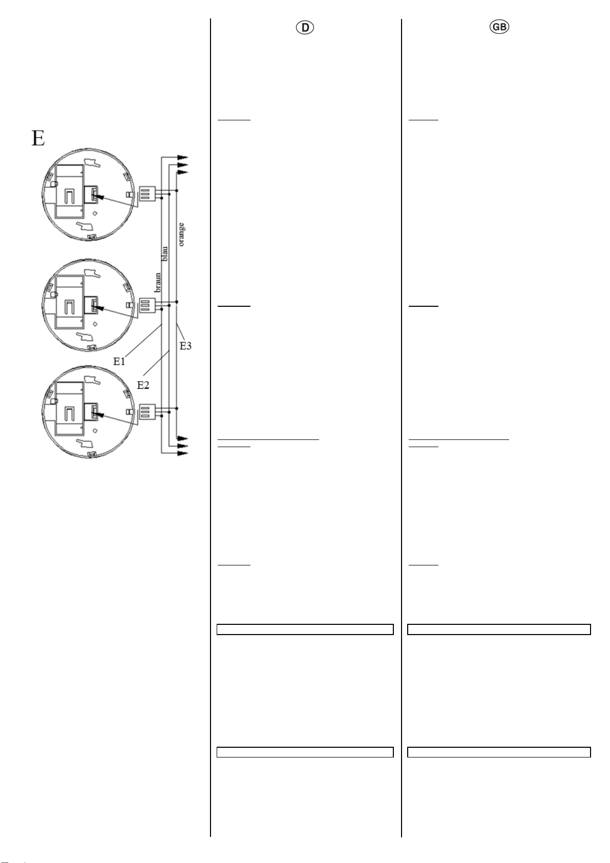
Vernetzung von Rauchmeldern:
ACHTUNG: Alle miteinander vernetzten Rauchmelder
müssen aus der selben Phase gespeist werden. Bei
Arbeiten an der Vernetzungsleitung ist die 230 V
Versorgung freizuschalten.
Neben dem Einzelbetrieb können bis zu 38 Rauchmelder
gleichen Fabrikats mit einer Ader mit mind. 0,8 mm² Querschnitt
vernetzt werden. Hierzu kann auch eine freie Ader der 230 V
Versorgungsleitung verwendet werden. Erfasst nun ein Melder
Rauch, so ertönt der Alarm gleichzeitig aus allen miteinander
vernetzten Geräten. Die Leuchtdiode blinkt nur an dem Melder,
der den Alarm auslöst. Dadurch kann der auslösende
Rauchmelder leicht ermittelt werden. Zum Vernetzen ist die
orange Ader (E3) an die Vernetzungsader anzuschliessen. Die
Gesamtlänge der Vernetzungsleitung darf 330 m nicht
überschreiten. Nach dem Vernetzen den Funktionstest
durchführen.
Networking of smoke detectors:
CAUTION: All networked smoke detectors must be supplied
from the same phase. The 230 V supply must be
disconnected whenever work is carried out on the networking
cable.
Up to 38 smoke detectors of the same make can be connected
together with a wire with a minimum cross section of 0.8 mm².
Therefore an unimplemented wire of the 230 V cable can be used.
If a detector now records smoke, the alarm is emitted from all the
interlinked devices at the same time. The LED only flashes on the
detector that triggered the alarm. It is therefore easy to determine
which smoke detector has been triggered. The connection of the
detectors connect the orange wire (E3) with the networking wire.
The total cable length of the interlinked smoke detectors may not
exceed 330 m. Carry out the functional test after interconnection.
ACHTUNG:
•Niemals offenes Feuer zum Testen des Rauchmelders
verwenden.
•Durch Dampf oder Staub kann ein Fehlalarm ausgelöst
werden. Sollte dies passieren, öffnen Sie das Fenster oder
sorgen Sie für Luftbewegung, um evtl. Staub oder Dampf in
der Luft abzubauen. Der Alarm wird dann automatisch
wieder aufhören. Wenn der Alarm andauert, überprüfen Sie
den Montageort oder tauschen Sie den Melder aus.
CAUTION:
•Never use an open flame to test the detector.
•A nuisance alarm can be caused by steam or dust. If this
happens, open a window or fan the air to remove the smoke or
dust. The alarm will then turn off automatically. If nuisance
alarm keeps going on, check the installation location or replace
the smoke detector.
Mögliche Brandursachen Possible causes of fire
Um Brände zu verhindern, sollten nachfolgende Brandursachen
vermieden werden:
•schadhafte elektrische Leitungen, falsche Verwendung und
Überhitzung von Elektrogeräten
•leicht brennbare Materialien neben sich stark erwärmenden
Elektrogeräten wie Bügeleisen, Toaster und Friteusen
•unbeaufsichtigtes offenes Feuer wie Kerzen, Kamine und
Teelichter
•Rauchen auf der Couch oder im Bett
•Kurzschlüsse durch Standby-Betrieb bei Radio, Fernseher
und Computern
•Überlastung und Überhitzung von Steckdosen durch
Mehrfachstecker
•verschmutzte Dunstabzugshauben mit Fettablagerungen
•mit Feuer spielende Kinder
To prevent fires, the following causes of fire should be avoided:
•Damaged electrical cables, incorrect usage and overheating of
electrical devices
•Flammable materials next to electrical devices that generate
high levels of heat such as irons, toasters and deep-fat fryers
•Unattended open flames such as candles, chimneys and
tealights
•Smoking on the sofa or in bed
•Short circuits caused by standby operation of radios,
televisions and computers
•Overload and overheating of sockets via multiway adapters
•Dirty extractor hoods with grease deposits
•Children playing with matches
Allgemeine Hinweise General notes
Ein defektes Gerät ist an die zuständige Geschäftsstelle der
Siemens AG zu senden.
Bei zusätzlichen Fragen zum Produkt wenden Sie sich bitte an
unseren Technical Support:
Die Bedienungsanleitung ist dem Kunden auszuhändigen
℡+49 (0) 180 50 50-222
+49 (0) 180 50 50-223
www.siemens.com/automation/service&support
Any faulty devices should be returned to the local Siemens office.
If you have further questions concerning the product, please
contact our technical support:
The operating instruction must be handed over to the client
℡+49 (0) 180 50 50-222
+49 (0) 180 50 50-223
www.siemens.com/automation/service&support

Other manuals for DELTA reflex SD230N

1

This manual suits for next models

1

Other Siemens Smoke Alarm manuals

Siemens AD2-C11 User manual

Siemens

Siemens AD2-C11 User manual

Siemens DELTA reflex 5TC1 290 Service manual

Siemens

Siemens DELTA reflex 5TC1 290 Service manual

Siemens FDOT421 User manual

Siemens

Siemens FDOT421 User manual

Siemens DOW1171 User manual

Siemens

Siemens DOW1171 User manual

Siemens 5TC1292-7 User manual

Siemens

Siemens 5TC1292-7 User manual

Siemens OP121 User manual

Siemens

Siemens OP121 User manual

Siemens AD1-C11 User manual

Siemens

Siemens AD1-C11 User manual

Siemens ILP-1 User manual

Siemens

Siemens ILP-1 User manual

Siemens OP121 User manual

Siemens

Siemens OP121 User manual

Siemens Sinteso Cerberus PRO FDA221 User manual

Siemens

Siemens Sinteso Cerberus PRO FDA221 User manual

Siemens DELTA reflex SD230N Service manual

Siemens

Siemens DELTA reflex SD230N Service manual

Siemens BH17 7ER User manual

Siemens

Siemens BH17 7ER User manual

Siemens Cerberus DLO1191 Guide

Siemens

Siemens Cerberus DLO1191 Guide

Siemens TITANUS 3000 User manual

Siemens

Siemens TITANUS 3000 User manual

Siemens AD2-C11 User manual

Siemens

Siemens AD2-C11 User manual

Siemens Cerberus DBW1171 User manual

Siemens

Siemens Cerberus DBW1171 User manual

Siemens Cerberus DO1101A-Ex Parts list manual

Siemens

Siemens Cerberus DO1101A-Ex Parts list manual

Siemens FDA241 Guide

Siemens

Siemens FDA241 Guide

Siemens DI-3 User manual

Siemens

Siemens DI-3 User manual

Siemens DM1101 User manual

Siemens

Siemens DM1101 User manual

Siemens FDA241 Technical manual

Siemens

Siemens FDA241 Technical manual

Siemens Synco living AP260 User manual

Siemens

Siemens Synco living AP260 User manual

Siemens 5TC1292-6 User manual

Siemens

Siemens 5TC1292-6 User manual

Siemens DB721-CN User manual

Siemens

Siemens DB721-CN User manual

Popular Smoke Alarm manuals by other brands

Linear DXS FORMAT DXS-72 installation instructions

Linear

Linear DXS FORMAT DXS-72 installation instructions

System Sensor D4P120 installation instructions

System Sensor

System Sensor D4P120 installation instructions

DSC WS4926 Series Installation and operating instructions

DSC

DSC WS4926 Series Installation and operating instructions

Universal 976LR instructions

Universal

Universal 976LR instructions

First Alert PC1210 user manual

First Alert

First Alert PC1210 user manual

Bavaria BARM210 user manual

Bavaria

Bavaria BARM210 user manual

Autronica AutroSense Nano Installation handbook

Autronica

Autronica AutroSense Nano Installation handbook

System Sensor 6424 Installation and maintenance  instruction

System Sensor

System Sensor 6424 Installation and maintenance instruction

DSC PG9936 Serires operating instructions

DSC

DSC PG9936 Serires operating instructions

Kidde FADC230 user manual

Kidde

Kidde FADC230 user manual

Nittan evolution EVC-P instruction manual

Nittan

Nittan evolution EVC-P instruction manual

Fyrnetics PE120 user guide

Fyrnetics

Fyrnetics PE120 user guide

TrueGuard Mini-SD-ZBS manual

TrueGuard

TrueGuard Mini-SD-ZBS manual

Edwards LaserSense 100 Installer's handbook

Edwards

Edwards LaserSense 100 Installer's handbook

Fireray FD2705R manual

Fireray

Fireray FD2705R manual

DSW DSW98D user manual

DSW

DSW DSW98D user manual

Kidde 0915 Guide

Kidde

Kidde 0915 Guide

Synova SynoDEC 300 OP320C Installation

Synova

Synova SynoDEC 300 OP320C Installation

manuals.online logo
manuals.online logoBrands
  • About & Mission
  • Contact us
  • Privacy Policy
  • Terms and Conditions

Copyright 2025 Manuals.Online. All Rights Reserved.