Sierra thermofon plano TP43 Installation and operation manual

TERMOCONVETTORE
CONVECTOR RADIATOR
thermofon® plano
TP ITA ENG MIT Ed.01 Rev.00
102008
MANUALE TECNICO E D’INSTALLAZIONE - TECHNICAL AND INSTALLATION BOOKLET

2
INFORMAZIONI GENERALI •
GENERAL INFORMATION………………………….………………......................2
CARATTERISTICHE •
FEATURES………………………………………………………………………………......................3
Descrizione dell’unità •
General description………………………………………………………………………………..…………..
Componenti principali •
Main components.............................................................…..................................
Imballo •
Packaging….………………………………………………………………………………………………………….………………
Modelli disponibili •
Models available……………………………………………………………………………………………….…..4
Descrizione dei componenti •
Description of the components.........……………………………………………………..…
Dati tecnici e dimensionali •
Technical data
and dimensions. ………………………………………………………………..5
Installazione dell’unità •
Installation
of the unit………………………………………………………………………………….. 7
Sostituzione di radiatori •
Substituting an existing radiator
…..……………………………………………….…………….
10
Trasporto •
Carriage
…………………………………………………………………………………………………………… ……. …..
11
Usi impropri •
Improper use
……………………………………………………………………………………………………………..
12
INFORMAZIONI GENERALI
Questo manuale descrive la macchina qui rappresentata.
Conservare i manuali in luogo asciutto, per evitare il
deterioramento, per almeno 10 anni per eventuali
riferimenti futuri.
Leggere attentamente e completamente tutte le infor-
mazioni contenute in questo manuale. Prestare parti-
colarmente attenzione alle norme d’uso accompagnate
dalle scritte “ATTENZIONE” in quanto, se non osservate,
possono causare danno alla macchina e/o a persone e
cose.
SIERRA S.p.A. declina ogni responsabilità per qualsiasi
danno dovuto ad un uso improprio della macchina, ad una
lettura parziale o superficiale delle informazioni contenute
in questo manuale.
Il numero di pagine di questo manuale è: 12
GENERAL INFORMATION
This manual describes the machine.
Store the manual in a dry location to avoid deterioration,
as it must be kept for at least 10 years for any future
reference.
All the information in this manual must be carefully read
and understood. Pay particular attention to the operating
standards with “WARNING” signals as their disrespect can
cause damage to the machine and/or persons or objects.
SIERRA S.p.A. declines all responsibility for any damage
whatsoever caused by improper use of the machine, and a
partial or superficial acquaintance with the information
contained in this manual.
This manual has 12 pages.

3
CARATTERISTICHE FEATURES
DESCRIZIONE DELL’UNITA’
Il termoconvettore Thermofon concentra elevate
caratteristiche tecnologiche e funzionali che ne fanno il
terminale ideale per il riscaldamento di ogni ambiente.
L’erogazione di calore avviene per convezione naturale,
grazie ad un esclusivo scambiatore alettato. L’erogazione
di calore è immediata e distribuita in modo uniforme in
tutto il locale; Thermofon genera calore se inserito in un
impianto termico alimentato con caldaia,
teleriscaldamento o pompa di calore. La possibilità di
rimuovere con facilità il leggero mobile di copertura
consente di eseguire una pulizia accurata delle parti
interne, condizione necessaria per l’installazione in luoghi
molto affollati o che richiedono uno standard elevato di
igiene.
Facilità di installazione con attacchi idraulici reversibili in
fase di installazione; idoneità a sostituire radiatori pre-
esistenti con interasse compreso tra 480 e 630 mm. Pieno
rispetto delle norme antinfortunistiche e di sicurezza.
DESCRIPTION
The Thermofon radiator-convector combines advanced
technical and operational characteristics, which make it
the ideal unit for residential heating. The excellent heat
distribution is due to natural convection by using an
exclusive finned heat exchanger. The heated air is
immediately delivered to the entire room; the Thermofon
produces warm air when fitted to heating system with a
boiler or a heat pump. The removable and light cover
ensures thorough cleaning of the unit, essential for
installations in venues subject to crowding or in those with
special hygienic requirements.
The Thermofon is easy to install, and reversible water
connections allow to choose a left or right installation;
Thermofon can also replace radiators with a distance from
“water-in pipe” to “water-out pipe” from 480 to 630 mm.
The Thermofon is in full compliance with the safety
regulations.
COMPONENTI PRINCIPALI
1Mobile di copertura
2Batteria di scambio termico (reversibile)
3Schienale posteriore di fissaggio a parete
4Collettore ingresso acqua
5Collettore uscita acqua
6Testata
7Valvola sfiato aria
8Convogliatore di flusso d’aria
MAIN COMPONENTS
1Cover
2Heat exchange coil (reversible)
3Rear frame for mounting against the wall
4Inlet water connection
5Outlet water connection
6Air distribution head
7Air bleeder
8Air Conveyor
IMBALLO
I termoconvettori vengono spediti con imballo standard in
cartone.
PACKAGING
The units are shipped in a standard cardboard box.

MODELLI DISPONIBILI
Il termoconvettore Thermofon plano è disponibile in 4
taglie di larghezza, 8 modelli.
Colore standard del mantello: RAL 9010.
MODELS AVAILABLE
Thermofon plano convectors is available in 4 sizes,
8 models.
Front panel colour is RAL 9010.
DESCRIZIONE DEI COMPONENTI
1 MOBILE DI COPERTURA
La sua forma arrotondata unisce alla gradevole estetica
maggior sicurezza contro gli urti accidentali. Disponibile
in colore RAL9010, è realizzato in lamiera verniciata a
caldo con polveri poliuretaniche dopo trattamento di
passivazione per garantire alta resistenza e durata nel
tempo.
2 BATTERIA DI SCAMBIO TERMICO
Progettata e studiata per esaltare al massimo l’effetto
convettivo naturale, è realizzata con tubi di rame ed
alettatura speciale in alluminio bloccata mediante
espansione meccanica dei tubi. La batteria di scambio
termico è reversibile, ossia è possibile il collegamento
idraulico a destra oppure a sinistra.
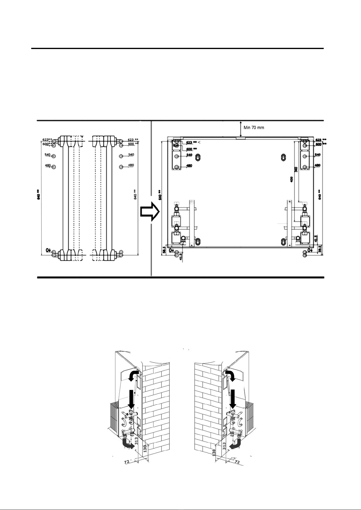
3 SCHIENALE DI FISSAGGIO POSTERIORE
È realizzato in lamiera zincata di forte spessore, ed è
dotato dei fori per il fissaggio al muro e d’apposite
sezioni (pre-tranciate) per il passaggio delle tubazioni
idrauliche, su entrambi i lati. Le zone di passaggio tubi
(pre-tranciate) poste sulla parte superiore, consentono la
sostituzione di radiatori con interasse compreso tra 480
fino a 630 mm.
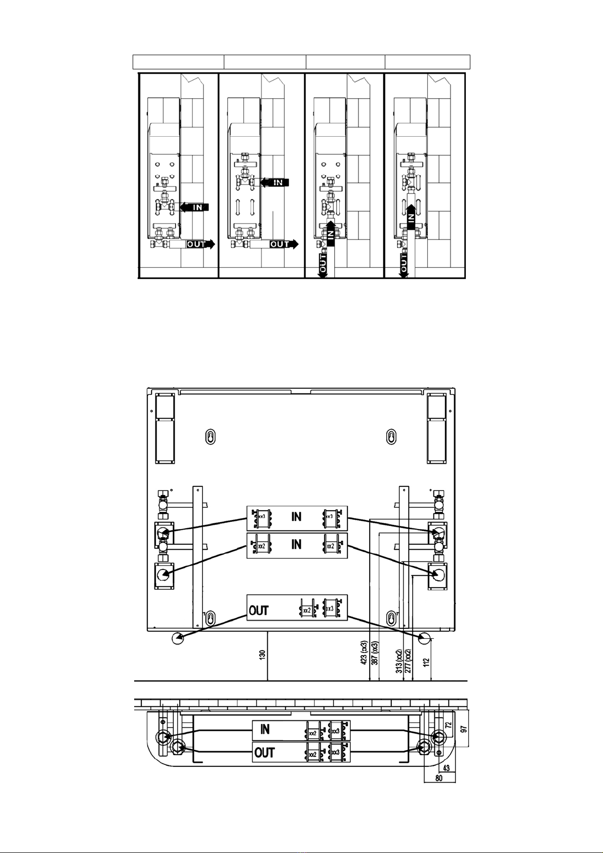
4-5 COLLEGAMENTI IDRAULICI
I collegamenti sono ad attacco femmina ½”. Data la
possibilità di ruotare la batteria, è possibile prevederne la
disposizione alla destra oppure alla sinistra. (4: attacchi
ingresso acqua; 5: attacchi uscita acqua dallo
scambiatore di calore).
6 TESTATA
Costituita da griglia in alluminio anodizzato.
7 VALVOLA SFIATO ARIA
È posta sul collettore superiore della batteria. Permette lo
sfiato dell’aria dalla batteria.
8 CONVOGLIATORE DI FLUSSO D’ARIA
Ottimizza il flusso d’aria ascendente, esaltando l’effetto
convettivo naturale.
DESCRIPTION OF PARTS
1 CABINET HOUSING
The rounded cabinet combines aesthetic appeal with
safety against accidental impact. Available in RAL 9010
colour, it’s made of hot painted steel panels with
polyurethane powder after passivation treatment against
rust and corrosion.
2 HEAT EXCHANGER COIL
Designed and studied in order to exalt the natural
convective thermal exchange, the coil is a copper pipe
coil with aluminium fins mechanically fitted by expansion
of the pipes. The coil can be reversed on site.
3 REAR BEARING FRAME
The frame is made from suitably thick sheet metal and is
galvanised to ensure protection against corrosion.
The rear of the frame has holes for wall mounting the
appliance and pre-blanked holes on both sides to allow
the passage of the hydraulic pipages.The pre-blanked
holes in the upper side allow the substitution of existing
radiators with a distance from “water-in pipe” to “water-
out pipe” from 480 to 630 mm.
4-5 WATER CONNECTIONS
The manifolds are provided with female joints (1/2”).
Since it’s concurred to reverse the heat exchanger, it is
possible to connect them on the right side or on the left
side of the rear bearing frame. (4: inlet water connection;
5: outlet water connection).
6 AIR DISTRIBUTION HEAD
Anodized aluminium grid.
7 AIR BLEEDER
The air bleeder is positioned at the top of the heat
exchanger coil.
8 AIR CONVEYOR
The air conveyors, on both sides, optimise the ascending
airflow, maximizing the natural convective heat flow.

5
DATI TECNICI E DIMENSIONALI •
TECHNICAL AND DIMENSIONAL DATA
(UNI EN 442)
Modello •
Model
TP TP 12 TP 13 TP 22 TP 23 TP 32 TP 33 TP 42 TP 43
Potenza termica nominale* (Q0)
Heating capacity (Q
0
)
W 910 1005 1350 1540 1750 2001 2205 2515
Portata acqua* (Pw)
Water flow (Pw)
l/h 78 87 116 135 150 176 190 221
Perdite di carico acqua*
Water pressure drop
kPa 0,22 0,26 0,50 0,72 0,95 1,36 1,31 1,91
Esponente** [n] n 1,31 1,28 1,31 1,28 1,31 1,28 1,31 1,28
Contenuto d'acqua
Water content
l 0,5 0,6 0,8 1,1 1 1,4 1,1 1,6
Peso netto
Net weight kg 12,1 12,5 14,9 15,6 18 18,7 21 21,9
Altezza (B)
Height
mm 630
Dati comuni /
Common data
Attacchi scambiatore termico
Heat exchanger
connections
φ
GAS 1/2" femmina
Lunghezza scambiatore termico
Heat exchanger length
mm 425 625 825 1025
Larghezza (A)
Width
mm 600 800 1000 1200
Profondità (C)
Depth
mm 140
*Condizioni/ Conditions EN 442:
Temperatura di ingresso acqua:
inlet water temperature
: Tiw = 75 °C
Temperatura di uscita acqua:
outlet water temperature
: Tuw = 65 °C (∆Tw = 10 °C)
Temperatura aria ambiente:
Room air temperature
: Ta= 20 °C (∆T0= 50 °C)
Pressione massima di esercizio:
maximum working pressure
: 8 bar
Temperatura massima di esercizio :
maximum working temperature
: 90 °C
** Per ∆Tmdiverso da ∆T0 = 50°C, la potenza termica Q1è: at ∆Tm≠∆T0(∆T0= 50 °C) the heating capacity is given by:
Esempio di calcolo/Selection example. modello/model: TP 43
Condizioni di funzionamento/ working data: Tiw = 60 °C ; Tuw = 50 °C ; Ta = 20 °C ∆Tm = (60 + 50)/2 – 20 = 35
Resa termica / Heating capacity: Q1= 2515 x (35/50) 1,28 = 1593 W
n
T
T
QQ ⎟
⎟
⎠
⎞
⎜
⎜
⎝
⎛
∆
∆
=
0
1
01
a
uwiw
mT
TT
T−
+
=∆ 2)(

6
RESA TERMICA / HEATING CAPACITY [W]
°C 80 75 70 65 60 55 50 45 40
21 3108 2775 2451 2135 1830 1535 1252 983 729
20 3176 2841 2515 2198 1890 1593 1308 1036 778
19 3244 2908 2580 2260 1951 1652 1364 1089 829
°C 80 75 70 65 60 55 50 45 40
21 2473 2208 1950 1699 1456 1221 996 782 580
20 2527 2261 2001 1749 1504 1268 1041 824 619
19 2581 2313 2052 1798 1552 1314 1085 866 659
°C 80 75 70 65 60 55 50 45 40
21 1903 1699 1501 1308 1120 940 767 602 446
20 1945 1740 1540 1346 1157 976 801 634 477
19 1986 1780 1580 1384 1195 1011 835 667 507
°C 80 75 70 65 60 55 50 45 40
21 1242 1109 979 853 731 613 500 393 291
20 1269 1135 1005 878 755 637 523 414 311
19 1296 1162 1031 903 780 660 545 435 331
°C 80 75 70 65 60 55 50 45 40
21 2733 2433 2143 1861 1589 1327 1078 841 619
20 2794 2493 2200 1916 1642 1379 1127 887 662
19 2855 2552 2258 1972 1696 1431 1176 934 706
°C 80 75 70 65 60 55 50 45 40
21 2174 1936 1704 1480 1264 1056 857 669 493
20 2222 1983 1750 1524 1306 1097 896 706 527
19 2271 2030 1796 1569 1349 1138 936 743 562
°C 80 75 70 65 60 55 50 45 40
21 1677 1493 1315 1142 975 815 661 516 380
20 1714 1530 1350 1176 1008 846 691 544 406
19 1752 1566 1385 1210 1041 878 722 573 433
°C 80 75 70 65 60 55 50 45 40
21 1130 1007 886 770 657 549 446 348 256
20 1155 1031 910 793 679 570 466 367 274
19 1181 1056 934 816 702 592 486 386 292
TP43
TP33
TP23
temperatura ambiente /
Room temperature
TP32
TP22
TP12
temperatura media acqua / average water temperature [(Tin+Tout)/2]; (∆t=10 °C)
temperatura ambiente /
Room temperature
temperatura ambiente /
Room temperature
temperatura ambiente /
Room temperature
temperatura ambiente /
Room temperature
temperatura ambiente /
Room temperature
temperatura ambiente /
Room temperature
temperatura ambiente /
Room temperature
TP13
TP42
temperatura media acqua / average water temperature [(Tin+Tout)/2]; (∆t=10 °C)

7
INSTALLAZIONE
Il convettore Thermofon deve essere installato
perfettamente orizzontale ed in posizione tale da
consentire la manutenzione ordinaria e straordinaria.
Stabiliti il tipo di installazione (allacciamenti idraulici a
parete o a pavimento) e definito il lato degli attacchi
idraulici (a destra o a sinistra) la successione delle fasi di
installazione è:
1) Fissaggio dello schienale alla parete.
2) Fissaggio dello scambiatore e dei convogliatori allo
schienale ed effettuazione degli allacciamenti idraulici.
3) Aggancio allo schienale del mantello di copertura.
INSTALLATION
Thermofon convector must be installed perfectly
horizontal and where is easily allowed the ordinary and
not-ordinary maintenance. The installation phases are:
1) Fix the rear frame at the wall.
2) Fix the heat exchanger coil and the conveyor to the
rear frame. Make the water connections.
3) Hook up the cabinet at the rear frame.
Per installare l’unità procedere come segue:
1) Utilizzare la dima prestampata sull’imballo - o lo
schienale (nel caso di installazione a parete) - per
definire la posizione dei collegamenti idraulici,
rispettando l’altezza minima consigliata da terra (100
mm - consigliato 130 mm) e la minima distanza dal lato
superiore dello schienale nel caso di installazione in
nicchia (ad es. sotto davanzale di finestra).
Nella figura sono illustrate le diverse possibilità di
installazione e sono indicati l’ingresso e l’uscita del fluido
termovettore (acqua):
To install the unit, proceed as follows:
1) Use the pre-printed template on the packaging - or the
rear frame (installation to wall) - in order to define the
position of the hydraulic connections, respecting the
minimal distance from the floor (100 milimeter –
suggested: 130 milimeter) and the minimal distance from
the top side of the rear frame in case of installation in
niche (for ex.: under window sill).
In the following picture are shown the different kinds of
installation and water inlet and water outlet positions.
WARNING!
USE PROTECTIVE
GLOVES!
ATTENZIONE!
UTILIZZARE
GUANTI
PROTETTIVI!

8
2) Nel caso di allacciamento idraulico a parete, definito il
lato del collegamento di ingresso acqua (IN) al circuito
idraulico e il tipo di scambiatore, si elimini il pretranciato
corrispondente. Chiudere con i tappi a corredo (2),
rispettivamente l’ingresso non utilizzato del collettore
superiore e l’uscita non utilizzata del collettore inferiore
dello scambiatore di calore. Per allacciamenti idraulici a
pavimento, utilizzare le quote riportate nel lato inferiore
della seguente figura.
2) In case of wall connection, once defined the water inlet
side (IN) and the heat exchanger type push-out the
correct slice. Close with the equipped stoppers(2), the
water inlet not used of the upper collector and the water
outlet not used of the inferior collector of the heat
exchanger. In case of hydraulics connections to floor,
refer to the dimensions shown on the bottom side of the
following picture.
TP X2 TP X3 TP X2 TP X3

9
3) Fissate lo schienale alla parete mediante 4 tasselli di
fissaggio (Ø 8 mm). 3) Fix the rear frame to the wall with 4 nails (Ø 8 mm).
4) Effettuate il fissaggio dello scambiatore allo schienale
utilizzando i 2 perni di aggancio (Frecce in neretto).
Fissate poi, tramite le 2 viti a corredo e gli appositi
incastri sulle spalle dello scambiatore, i 2 convogliatori di
flusso (Frecce in grigio). Effettuate gli allacciamenti
idraulici.
4) Fix the heat exchanger coil to the rear frame using the
2 coupling hinges (black arrow). Then fix the two air
conveyors, with the 2 joints (grey arrow down) and the 2
screw on the top (grey arrow). Connect the water pipes
to the hydraulic connections of the heat exchanger.
4) Agganciate il mantello di copertura allo schienale in
corrispondenza ai 4 perni posti ai lati. 4) Hitch the cabinet at the rear frame, by inserting the 4
holes on the both sides in the 4 hinges of the rear-frame.

10
Utilizzare l’ingresso acqua rivolto verso l’alto del
collettore superiore dello scambiatore, chiudendo con il
tappo a corredo l’ingresso acqua rivolto verso il basso del
collettore superiore.
Connect the water inlet pipe to the upper connection on
the superior collector of the heat exchanger. Close with
the equipped stopper the lower connection of the superior
collector.
SOSTITUZIONE DI RADIATORI
Nella figura sottostante sono riportati i valori degli
interassi dei radiatori che possono essere sostituiti.
Eliminate il pre-tranciato dallo schienale di fissaggio di
thermofon in corrispondenza della tubazione superiore di
allacciamento idraulico del radiatore da sostituire.
Rispettare la distanza minima, nel caso di installazione in
nicchia.
RADIATORS’ SUBSTITUTION
In the figure below are shown the values of the distance
between inlet pipe and outlet pipe of the radiators that
can be replaced by thermofon. Push-out the correct slice
on the top of the rear frame.
Respect the minimal distance from the top side of the
rear frame in case of installation in niche (for ex.: under
window sill).
IN
OUT OUT
IN

11
TRASPORTO ●CARRIAGE
UTILIZZI IMPROPRI ●IMPROPER USES

12
SIERRA S.p.A
Via Cà Magre,45 – 37063 ISOLA DELLA SCALA (VR)
Company Quality System Certified according to EN ISO 9001: 2000
WWW.SIERRA.IT
dati tecnici riportati nella presente documentazione non sono impegnativi.
SIERRA S.p.A. si riserva la facoltà di apportare in qualsiasi momento tutte le
modifiche ritenute necessarie per il miglioramento del prodotto.
Technical data shown in this booklet are not binding. SIERRA S.p.A. shall have
the right to introduce at any time whatever modifications deemed necessary
to the improvement of the product.
This manual suits for next models
7
Table of contents
Other Sierra Heater manuals
Popular Heater manuals by other brands

Ebasto
Ebasto Thermo Top TTC operating instructions

DELLA
DELLA 048-H26F manual

GoodHome
GoodHome Iriya manual

eltherm
eltherm ELK-AE installation manual

Olimpia splendid
Olimpia splendid Vapore Alogena Instructions for installation, use and maintenance

Hyundai power products
Hyundai power products HY70DKH instruction manual