manuals.online logo
Brands
  1. Home
  2. •
  3. Brands
  4. •
  5. SIGMA TEK
  6. •
  7. Computer Hardware
  8. •
  9. SIGMA TEK FDD 3000 User manual

SIGMA TEK FDD 3000 User manual

FDD 3000 COMMISSIONING
07.06.2022 Page 1
FDD 3000 Commissioning Quick-Start Guide
This document serves as a quick guide for wiring, starting, and controlling an FDD 3000 AC drive via CANopen and
Sigmatek CPU. For more detailed information, see the operating manual of the respective FDD.
Checking the Contents of Delivery and Mains Voltage Compatibility
•Check whether the power supply is compatible with the voltage range of the FDD.
Mains voltage Volts / Voltage range of the AC drive Volts
For details, see the product key on the right panel of the FDD.
Assembling the FDD and Wiring the Power Element
Remove housing terminal cover
The wiring can only be installed when NO power is applied.
•Ensure there is a proper connection to ground.
•Check the rated power of the power switch or fuse
•Check whether the motor voltage is compatible with the FDD voltage. Motor voltage Volt.
•Connect motor to the FDD
•Connect FDD to the supply. However, do not turn the power on yet
Single-phase supply => connect supply voltage to L1 and L3
3
FDD 3000 COMMISSIONING
Page 2 07.06.2022
Wiring the STO (Safe Torque Off)
•The terminal block is located int he slot for the communication module and is removed for the wiring.
Wiring the CANopen bus connection
•For the pin assignment on the CPU side, see the manual for the CPU used (download from SIGMATEK website).
Remove the protective cover from the slot with a
screwdriver and install the communication module.
•Wire the CANopen communication module.
Install terminating resistor (120 Ω, 0.25 W)
between CAN-H and CAN-L of the last
participant.
Pin assignment: Pin 1: 0 V external power supply (black)
Pin 2: CAN-L negative data line (blue)
Pin 3: Cable screen (braided shield)
Pin 4: CAN-H positive data line (white)
Pin 5: +24 V external power supply (red)
The additional +24 V supply (Pin 1 and Pin 5) does not have to be connected. It serves as a back-up supply for the
control component if the power supply fails.
Voltage Supply FDD
•Check wiring
•Turn the FDD supply voltage on
Commissioning the SIGMATEK CPU
•Wire the CPU supply voltage as described in the manual of the respective CPU.
•Start LASAL CLASS 2 and create a new project
•Open the hardware editor
•Add the CPU used to the project
•Extend the tree structure of the CPU so that the CAN interfaces are visible
•Add the CanOpen Manager to the CAN interface used to communicate with the FDD. For this purpose, open the
context menu with a right-click on the interface.
•Open the tree structure of the CANopen manager and add the FDD3000 AC drive to the desired CAN slot. Right-
click on a slot to open the context menu. The “CanOpen:00” slot corresponds to the node number 0 and is
reserved for programming the communication module via the bus. Node numbers can be freely assigned starting
from “CANOpen:01” (node number 1) upwards.
FDD 3000 COMMISSIONING
07.06.2022 Page 3
•By selecting “FDD3000_AxisCan”, a corresponding class is placed in HW_Network.
The “FDD3000_CanOpen” corresponds to an older version. It should not bd used, as the class is no longer
supported.
FDD 3000 COMMISSIONING
Page 4 07.06.2022
Placing a Table for the Motor Data
•ParaSaveType = 0
The parameters of TableBase (or a derivation thereof) are sent when starting the FDD.
•ParaSaveType = 1
The parameters are stored in the CPU and sent when starting the FDD.
A TableBase must also be placed here since the table contains the data structure for the SRAM data.
•ParaSaveType = 2
The parameters are stored in the CPU as a RAM files and when starting the FDD.
A TableBase must also be placed here since the table contains the data structure for the RAM file.
Configuration of the PLC CAN Communication
•Baud rate configuration of the CAN communication in the application.
Select the “_CanOpenMng” class in the tree structure of the hardware editor to display the class properties. The
Baud rate is set vie the “Baud rate Can” parameter. The CPU and AC drive are delivered with preconfigured Baud
rate of 500 kbits/s.
•Select the node number configuration in the application from the tree structure of the hardware editor of the
“FDD3000_AxisCan” class.
FDD 3000 COMMISSIONING
07.06.2022 Page 5
•In the properties, the desired node number (CAN-ID) can be set in the value “Place”.
Configuration of the Drive CAN communication over VOV
•Configuration of the drive CAN communication via the VOV.
The VOV is thereby opened with a right-click on the FDD3000_AxisCan object.
•When configuring the CAN communication over the VOV, the node number and Baud rate are always sent. The
process for changing the Baud rate, as well as the node number is therefore identical.
In the VOV, the page on which the communication settings for the controller can be made, opens using the “CAN
SETUP” button.
•In this menu, the CAN object number (NodeID) and Baud rate can be set by SI-Canopen. The CanOpen LSS
protocol is thereby used.
Ensure that only one FDD 3000 is connected with SI-Canopen on the CAN bus.
•The SI-Canopen is delivered with NodeID=0 and Baudrate=500kbps configured. NodeID=0 means deactivated,
and the SI-Canopen only reacts to LSS command.
•Since this is the default setting of the SI-Canopen, the Can-participant search and configuration of the NodeID and
baud rate is performed with 500kbps by default. This can cause problems with longer cable lengths and prevent
the setup. In this case, the Baudrate must be configure using the display on the FDD 3000 (See following section).
The changed Baudrate can then be set in the VOV as the Baudrate for the SI-Open.
•When the search is performed with a Baudrate that does not match the SI-Canopen Baudrate, communication
errors occur. This can cause the FDD 3000 to change to a “BusOff” status and need to be turned on then off to be
accessible on the CAN bus again. This response should only occur when another NodeID is already configured in
the SI-Canopen as 0.
FDD 3000 COMMISSIONING
Page 6 07.06.2022
•The configuration is started via the “Start” button.
•Setup complete
•If the axis is already communicating, the setup cannot be started.
FDD 3000 COMMISSIONING
07.06.2022 Page 7
Configuration of the Drive CAN Communication via the Drive Display
•Node number configuration (NodeID)
oPress Enter (6)
oSelect “Pr. 10” using Up/Down (2/5)
oPress Enter (6)
oStart processing with the Enter key
oSelect “ALL” using UP/Down (2/5)
oPress Enter (6), then Escape (1)
oPress Enter (6), select 1.00.000 with the Up/Down buttons (module slot 1)
oPress Enter (6), select 1.01.000 with the Up/Down (2/5) (CanOpen parameter)
oPress Enter (6), select 1.01.004 with the Up/Down (2/5) (Node Address)
oPress Enter (6), start processing with the Enter key
oSelect the desired node number with Up/Down (2/5)
oPress Enter (6), return to the start with the Escape key
After these steps, the drive must be reset so that the new node number can be activated!
1. Escape button
2. Down button
3. Start button (green)
4. Stop/Reset button (red)
5. Up button
6. Enter button
7. Run forward indicator
8. Run reverse indicator
9. Keypad reference indicator
FDD 3000 COMMISSIONING
Page 8 07.06.2022
oPress Enter (6)
oSelect 1.01.002 with the Up/Down buttons (2/5) and Enter (6)
oPress Enter (6), start processing with the Enter key
oSelect “On” with the with the Up/Down buttons (2/5)
oPress Enter (6), reset is triggered
After these steps, the configuration must then be saved.
oSelect 1.01.000 with the Up/Down buttons (2/5) and Enter (6)
oPress Enter (6), start processing with the Enter key
oSelect “Save” with the Up/Down buttons (2/5)
oPress Enter (6)
oPress Stop/Reset (4), the parameters are then saved
FDD 3000 COMMISSIONING
07.06.2022 Page 9
Starting Communication
•Compile the project and load it into the CPU.
•Set the CPU in RUN mode. The connection is started while booting.
Configuring the Motor Parameters
•The motor parameters are always sent from the class to the drive.
•Configuration of the motor parameters over the VOV of the “FDD3000_AxisCan” class.
•The motor parameters are immediately sent with a change to the FDD.
If ParaSafeType = 1 or ParaSafeType = 2, the changed values are stored in the SRAM or the RAM file
.
If ParaSafeType = 0, the changed values must be adapted in the table or in their derivation since the values take
effect with the next start.
FDD 3000 COMMISSIONING
Page 10 07.06.2022
Running the Autotune Function
•Using the autotune function, the FDD automatically determines parameters for optimal operation. This step is not
required. The autotune function is started through the VOV of the “FDD3000_AxisCan class”.
A selection can be made between the “stationary” (motor not turning) and “rotating” (motor turning) autotune
function. With a stationary autotune, very good results are achieved for most applications. The dynamic autotune
however, measures the motor parameters in detail. Whenever possible, dynamic autotuning is recommended. To
start, one of the two buttons is pressed.
Performing a motion
•The motor can be operated via the “Move Manual” menu in the “FDD3000_AxisCan” class.

Other SIGMA TEK Computer Hardware manuals

SIGMA TEK S-DIAS AI 084 User manual

SIGMA TEK

SIGMA TEK S-DIAS AI 084 User manual

SIGMA TEK C-IPC User manual

SIGMA TEK

SIGMA TEK C-IPC User manual

SIGMA TEK CP 733 User manual

SIGMA TEK

SIGMA TEK CP 733 User manual

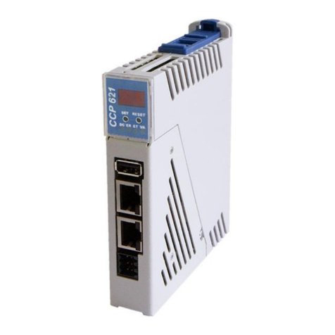
SIGMA TEK CCP 621 User manual

SIGMA TEK

SIGMA TEK CCP 621 User manual

SIGMA TEK SIB 061 User manual

SIGMA TEK

SIGMA TEK SIB 061 User manual

SIGMA TEK C-DIAS CSCP 012 User manual

SIGMA TEK

SIGMA TEK C-DIAS CSCP 012 User manual

SIGMA TEK CP 313 User manual

SIGMA TEK

SIGMA TEK CP 313 User manual
SIGMA TEK CP 731 User manual

SIGMA TEK

SIGMA TEK CP 731 User manual

SIGMA TEK CP 212-1 User manual

SIGMA TEK

SIGMA TEK CP 212-1 User manual

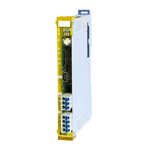
SIGMA TEK S-DIAS SCP 111 User manual

SIGMA TEK

SIGMA TEK S-DIAS SCP 111 User manual

SIGMA TEK CP 311 User manual

SIGMA TEK

SIGMA TEK CP 311 User manual
SIGMA TEK CCP 521 User manual

SIGMA TEK

SIGMA TEK CCP 521 User manual

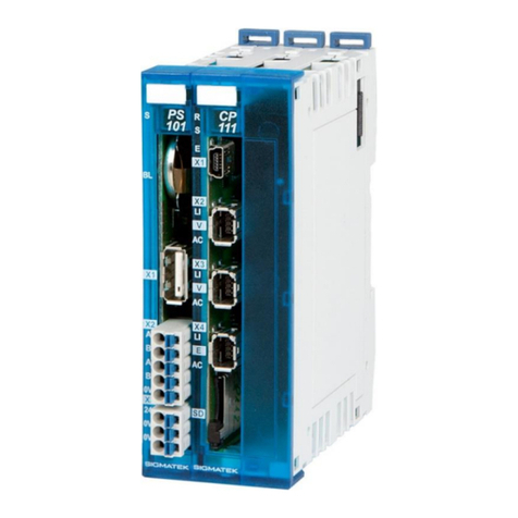
SIGMA TEK CP 111-1 User manual

SIGMA TEK

SIGMA TEK CP 111-1 User manual

Popular Computer Hardware manuals by other brands

NEC IE-V850ES-G1 user manual

NEC

NEC IE-V850ES-G1 user manual

Adaptec ATA II 1220SA Installation and user guide

Adaptec

Adaptec ATA II 1220SA Installation and user guide

Alphacool GPX-N 2060 M01 quick start guide

Alphacool

Alphacool GPX-N 2060 M01 quick start guide

KWG GEMINIE11201 Step By Step Installation Guide

KWG

KWG GEMINIE11201 Step By Step Installation Guide

Hewlett Packard Enterprise 200 Series user guide

Hewlett Packard Enterprise

Hewlett Packard Enterprise 200 Series user guide

Bosch FPE-1000-SLC installation guide

Bosch

Bosch FPE-1000-SLC installation guide

Wavecom GX64 Application note

Wavecom

Wavecom GX64 Application note

EK-Quantum Monoblock Series user guide

EK-Quantum

EK-Quantum Monoblock Series user guide

Honeywell PW7K1R1E Installation and configuration guide

Honeywell

Honeywell PW7K1R1E Installation and configuration guide

Intel LGA1155 SOCKET - THERMAL MECHANICAL S AND DESIGN GUIDELINES... installation instructions

Intel

Intel LGA1155 SOCKET - THERMAL MECHANICAL S AND DESIGN GUIDELINES... installation instructions

Akasa ALUCIA H4 PLUS user manual

Akasa

Akasa ALUCIA H4 PLUS user manual

Alinx AN9134 user manual

Alinx

Alinx AN9134 user manual

Pinnacle PCTV HDTV Sat Pro USB user manual

Pinnacle

Pinnacle PCTV HDTV Sat Pro USB user manual

Magma ExpressBox7 Quick installation guide

Magma

Magma ExpressBox7 Quick installation guide

Renesas QB-MINI2-RF Setup guide

Renesas

Renesas QB-MINI2-RF Setup guide

Meinberg TCR510PCI operating instructions

Meinberg

Meinberg TCR510PCI operating instructions

ekwb EK-FC980 INSTALLATION AND MOUNTING MANUAL

ekwb

ekwb EK-FC980 INSTALLATION AND MOUNTING MANUAL

Sundrax DimGate DIN user manual

Sundrax

Sundrax DimGate DIN user manual

manuals.online logo
manuals.online logoBrands
  • About & Mission
  • Contact us
  • Privacy Policy
  • Terms and Conditions

Copyright 2025 Manuals.Online. All Rights Reserved.