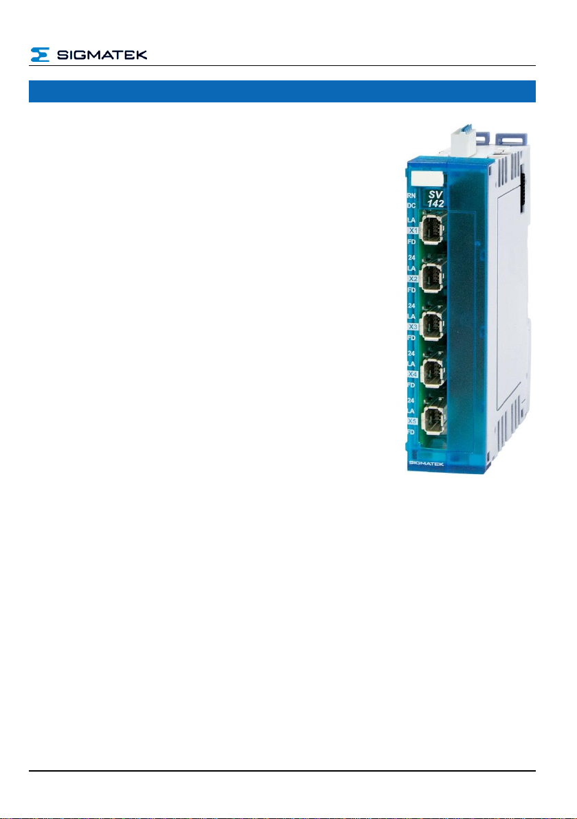
SV 142 S-DIAS SPLITTER VARAN
Page 2 02.08.2019
Contents
1Introduction............................................................................. 4
1.1 Target Group/Purpose of this Manual ........................................4
1.2 Important Reference Documentation .........................................4
1.3 Contents of Delivery.....................................................................4
2Basic Safety Guidelines......................................................... 5
2.1 Symbols Used...............................................................................5
2.2 Disclaimer......................................................................................6
4Technical Data ........................................................................ 9
4.1 Performance Data.........................................................................9
4.2 Electrical Requirements...............................................................9
4.3 Miscellaneous .............................................................................10
4.4 Environmental Conditions.........................................................10
5Mechanical Dimensions........................................................11
6ESD Protection.......................................................................12
7Connector Layout..................................................................13
7.1 Front View....................................................................................13
7.1.1 Status LEDs.......................................................................................14
7.1.2 Connectors........................................................................................14
7.1.3 VARAN Wiring Guidelines.................................................................15
7.2 Top View......................................................................................16