ATTENTION: Install in accordance with national and local building and electrical codes.
! Page 3
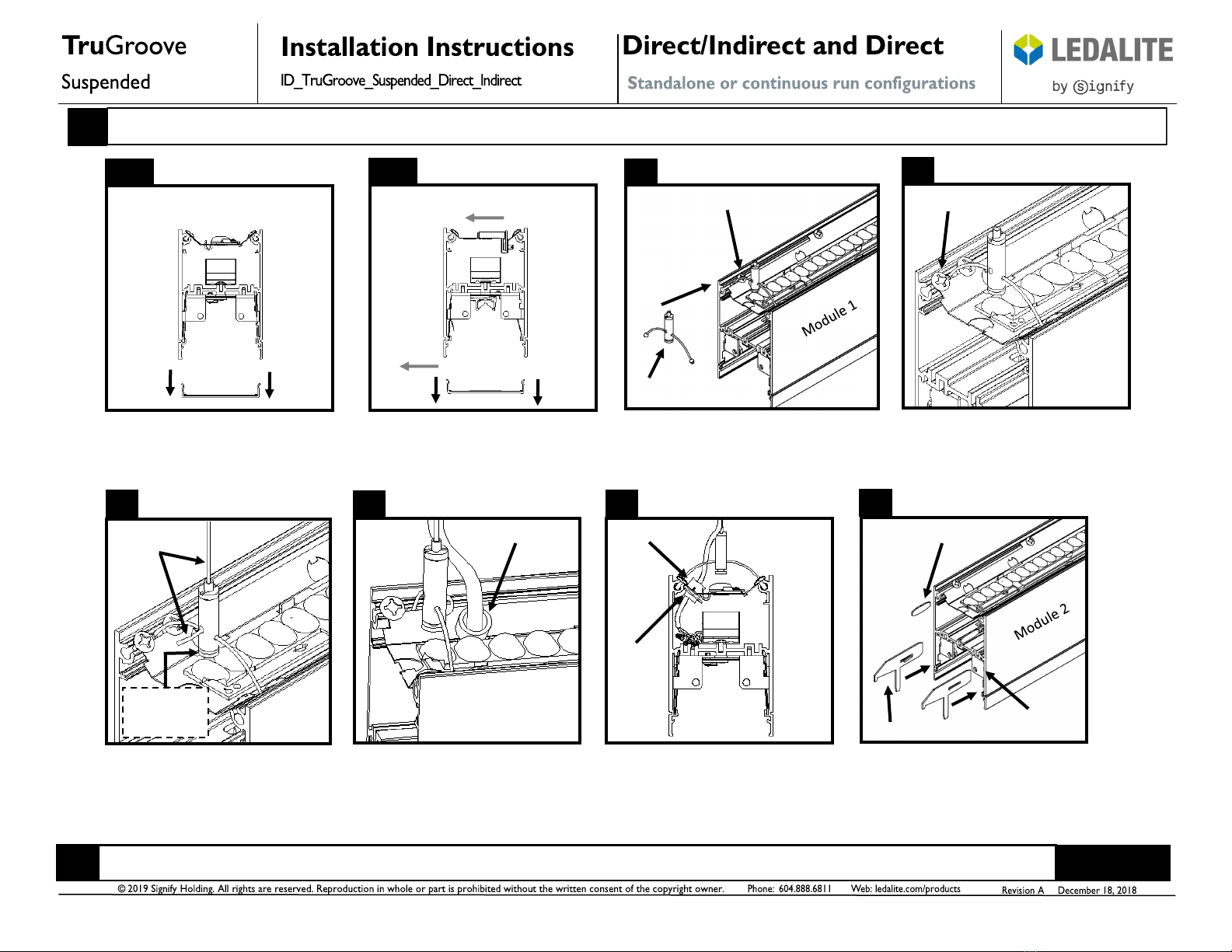
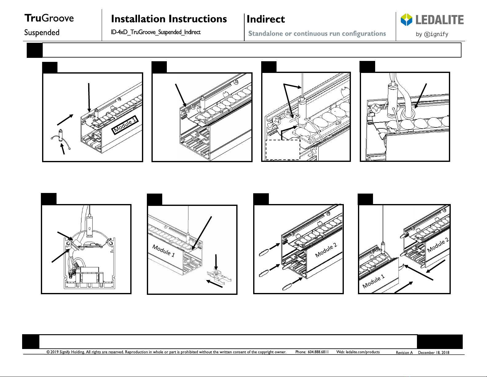
Module 1 Module 2
Ensure all connections are secure and all
wires are neatly tucked inside fixture
wiring cavity. Slide fixture modules
together gently.
Secure fixture modules together using the
two #10-32 machine screws and the two
#10-32 nuts supplied. Tighten until joint
seam is tight. Note: Do not overtighten.
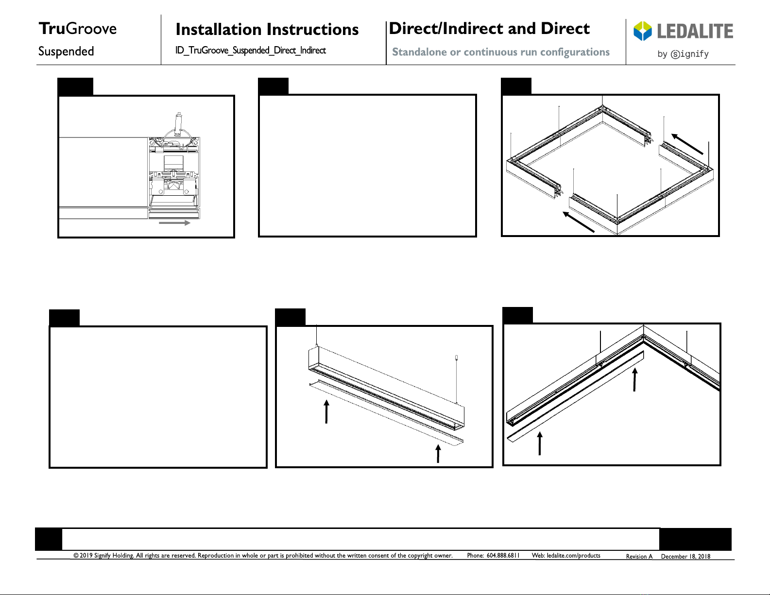
Slide endcap onto end of fixture module
and secure from below using two #8-32 X
5/16” screws. Ensure excess aircraft cable
does not interfere with endcap attach-
ment. Tighten screws until endcap seam is
tight. Note: Do not overtighten.
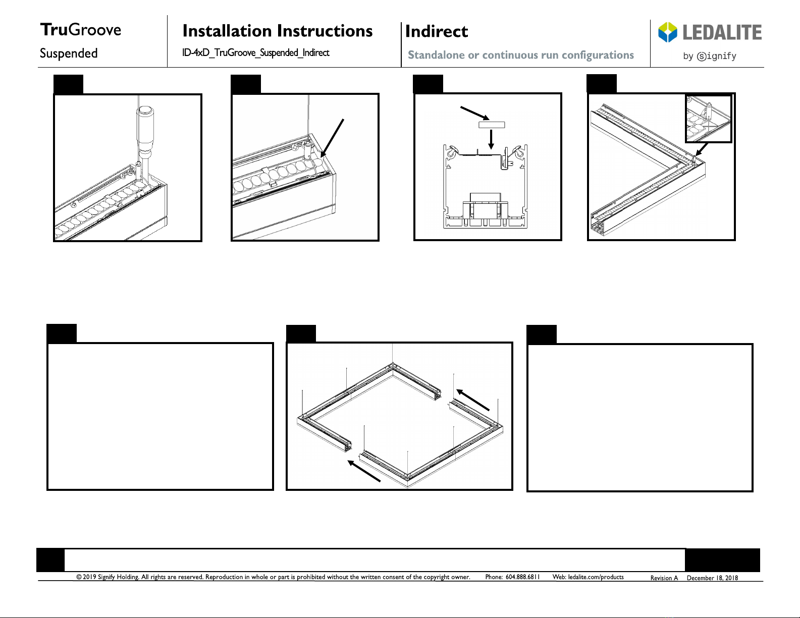
Factory
installed
corner
mount
Asymmetric Inside Cross Secon
Direcon of light
Symmetric Cross Secon
910 11 12
13 14
Bring modules together and engage joiner
aligners in module 2 on fixture bracket in
module 1. With fixtures modules supporting
each other, complete wiring connections
between modules.
15a 15b
If a corner is required, it is recommended
the 2’X2’ corner module be installed
first. All corners come with a factory
installed cable sling assembly in the mid-
dle. Refer to supplied corner run layout
drawings and figures 15a, 15b and 15c for
correct locations and corner orientation.
Graphic above shows a symmetric corner
cross-section. Refer to supplied layout
drawings for mounting locations.
Graphic above shows the direct/indirect
inside asymmetric corner cross-
section. This corner directs all lower
light toward the inside of the corner.
Refer to supplied layout drawings for
required corner orientation (direction of
light) and mounting locations.
#10-32 Screw
#10-32 Nut
Quick Wire
Connectors
(Supplied)
Raise module 2 to installed module 1
position.
Important: Use Wire Nuts ( Supplied By
Others) At Power Feed Location
Fixture Joining Fixture Joining Fixture Joining Fixture Joining
Endcap Installation Corner Installation Corner Installation Corner Installation