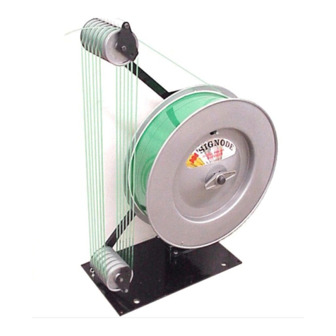
Signode DF-2D Instruction Manual

DF-2D
STRAP DISPENSER

2
READ THESE INSTRUCTIONS CAREFULLY. FAILURE TO FOLLOW THESE INSTRUCTIONS CAN
RESULT IN SERIOUS PERSONAL INJURY.
GENERAL SAFETY CONSIDERATIONS
1. EYE INJURY HAZARD.
Failure to wear safety glasses with side shields can result in serious eye injury or
blindness. Always wear safety glasses with side shields which conform to ANSI
Standard Z87.1 or European Norm 166.
2. CUT HAZARD.
Handling strap or sharp parts could result in cut hands or fingers. Wear
protective gloves.
3. TRAINING.
This dispenser must not be used by persons not properly trained in its use. Be certain that
you receive proper training from your employer. If you have any questions contact your
Signode Representative.
4. DISPENSER CARE.
Take good care of this dispenser. Inspect and clean it weekly. Replace any worn or broken
parts.
5. WORK AREA.
Keep work areas uncluttered and well lighted.
SAFETY PROCEDURES FOR DISPENSER OPERATION
Before loading a coil of strap into the dispenser, read the loading and safety instructions.
1. Follow the loading and threading instructions.
2. Maintain proper footing and balance when loading dispenser.
3. Do not load dispenser when you are in an awkward position. Strap coils can be heavy. To
prevent back or other bodily injuries, your employer may also contact the National Safety
Council, Itaska, IL 60143 U.S.A. for additional information on lifting techniques.
4. When mounting dispensers on wall and/or columns, use the proper Signode suspension
brackets.
CUTTING TENSIONED STRAP
Use only cutters designed for cutting strap; never use claw hammers, crowbars, chisels, axes or
similar tools. Such tools will cause the strap to fly apart with hazardous force. Before using any
Signode product read its Operation and Safety manual.

3
DF-2D
Dual Coil Dispenser
Right-Hand Version
Part No. 593041
Left-Hand Version
Part No. 593100
TABLE OF CONTENTS Page
General Safety Instructions 2
Introduction 3
Specifications 4
Major Components 4
Loading & Threading 5
Threading Diagram 9
Brake Adjustment 10
Parts List & Exploded Views 12
Recommended Spare Parts 13
Troubleshooting 18
INTRODUCTION
The DF-2D Dispenser’s unique dual coil design allows the operator to load coils at his
convenience while having minimal downtime to switch from one strap coil to another. Loading
strap is easy and fast, potentially eliminating any machine downtime to reload. The DF-2D’s
braking system allows for a “non-shock” payoff and accumulation reducing the potential for
strap to tangle or jam. Approximately five to six feet of strap is accumulated by the DF-2D as it
operates. This dispenser is available as a left-hand and right-hand version to suit any application
with improved convenience.
This dispenser can also be converted from a right-hand to a left-hand configuration after being
purchased. Contact your local Signode Sales or Service Representative for assistance.

4
SPECIFICATIONS
MODEL STRAP
DF-2D TYPE WIDTH COIL DIMENSIONS
Polyester or Polypropylene Up to 16mm. 24" OD x 16" ID x 6" W
NOTE: Use proper lifting techniques when placing strap coil in dispenser
MAJOR COMPONENTS

5
DF-2D LOADING AND THREADING INSTRUCTIONS
The DF-2D dispenser’s design allows for strap coils to be loaded independently of each other.
However the instructions are the same for loading either side. Use the threading diagram shown
on page 8 for reference. To load (or reload) a coil of plastic strap follow the steps below:
Strap coils can be heavy. To prevent back or other bodily injuries, your employer may also
contact the National Safety Council, Itaska, IL 60143 U.S.A. for additional information on
lifting techniques. Failure to follow the above could result in serious injury.
1. Remove the wing nut by turning it
counterclockwise. Remove the outer
reel disc assembly. If applicable, remove
the paper core and any plastic shrink
film residue left over from the previous
strap coil.
2. Position the new coil of strap on the
back disk so that the arrows printed on
the corrugated belly-band point in the
same direction as the arrow decal on the
inner reel disk.
Pay-off rotation must towards the rear of
the dispenser from the bottom of the
coil.
3. Reinstall the outer reel disc assembly.
Install and securely tighten the wing nut.
Continued . . .
Hand tighten the wing nut as mush as
possible.
Failure to snug the wing nut tightly
against the outer disk could result in the
disk and strap coil falling to the ground
or the wraps of the strap becoming
entangled.

6
LOADING AND THREADING, Continued
4. Confirm payoff direction by making sure
the that arrows printed on the
corrugated belly-band point towards the
strap guide roller and wire keeper.
5. Unhook the loading latch from the end of
the upper arm assembly.
6. Raise the lower arm up and secure it in
place by hooking it to the loading latch
using the head of the cap screw from the
lower arm assembly.
7. Remove the plastic film from the coil,
remove the corrugated belly-band and
remove the tape that secures the lead
end. Thread the lead end of the strap
through the brake arm roller and keeper.
Refer to threading diagram shown on
page 9 of this manual. Continue to
thread the strap into the strap guide
tube.
8. Continue to thread the strap from the
strap guide over the first upper idler
wheel. Make sure to thread the strap
through the roller assembly as shown.

7
LOADING AND THREADING, Continued
NOTE: The strap can also be threading
over the idler wheels by inserting the
strap from the side by pushing the
spring loaded keeper roller back
allowing the strap to pass under as
shown.
9. Continue to thread the strap under the
first lower idler wheel.
10. Continue threading the strap up to the
next idler wheel. Continue threading the
strap through all idler wheels. Refer to
the threading diagram on page 8 if
necessary.
11. Once all idler wheels have been threaded
properly, hold the strap end taunt to
keep the strap from unthreading from the
idler wheels.
12. Release the lower arm from the loading
latch. Return the loading latch back up
to its resting position. The lower arm will
begin to slowly drop. As the arm drops,
strap will begin to payoff from the coil.
NOTES: Once the arm has dropped the
brake will engage stopping the coil of
strap from spinning. Not placing the
loading latch back to its resting position
could interfere with the operation of the
dispenser.

8
DF-2D THREADING DIAGRAM
NOTE: The threading pattern is the same for both strap coils of the dispenser.

9
BLANK

10
DF-2D BRAKE PAD ASSEMBLY
Lower the
hex nuts on
the brake
rod to
have the
dispenser
brake
engage
sooner.
Raise the
hex nuts on
the brake
rod to
have the
dispenser
brake
engage later.
DISPENSER ADJUSTMENTS
WEAR SAFETY GLASSES WITH SIDE SHIELDS WHICH CONFORM TO ANSI STANDARD Z87.1
OR EN 166. FAILURE TO WEAR SAFETY GLASSES COULD RESULT INN SEVERE PERSONAL
INJURY. PROTECT YOUR EYES.
!Only trained people should service this dispenser.
!Unless specified, shutoff and lock out all electrical power.
!Follow all service instructions.
!Never adjust, repair or oil moving machinery.
READ THE GENERAL SAFETY INSTRUCTIONS IN THE FRONT OF THIS MANUAL.
COIL BRAKE
The DF-2D brake engages when the brake rods which are
connected to the lower arm are lowered as the arm swings
down. As the brake rods lower the brake pad arms pivot
downward to engage the brake pad against the inner contact
surface of the disk flanges. The amount of brake pretravel is
adjusted by moving the hex nut (two per brake rod) positions.
The amount of strap accumulated from the strapping machine
by the dispenser is dependent upon the position of the lower
arm when the brake is engaged. If the brake engages too late, as
the arm descends, very little strap can be retracted and
accumulated. If the brake engages too soon the arm may not
lower to the full bottom position.
NOTE: Since proper strap accumulation also depends on the
application, the factory setting must be considered nominal and
some fine tuning may be required.
To adjust the brake engagement point, rotate the two sets of hex nuts (four hex nuts total) up or
down the brake rods as required. Turn the nuts even amounts of turns to keep the distance from
one nut to the other from changing.

11
BLANK

12
PARTS LIST & EXPLODED VIEWS
KEY QTY PART# DESCRIPTION
1 2 593043 Chute, Dual Coil Dispenser
2 2 422294 Roller
3 2 593047 Keeper, Strap Guide
4 2 593046 Weldment, Back Disc
5 7 593050 Flat Belt Idler
6 7 593051 Clevis Adapter, Flat Belt Idler
7 1 593052 Weldment, Dispenser Post
8 1 593104 U-Bolt, 1" center to center x 2 1/4" rod size
9 2 593103 Clamp, Appleton #503154001, 1 hole, 1/2" Conduit
10 7 593165 Wave Spring
11 1 593044 Arm, Half
12 1 593073 Plate, Floor Mount
13 1 593075 Bracket, Brake Mounting
14 7 593166 Spacer, Tubular
15 2 593077 Arm, Brake Mounting
16 2 593078 Rod, Brake Lever
17 2 422295 Brake Pad
18 1 593081 Arm, Dancer
19 1 593082 Arm, Upper
20 7 593163 Keeper Roll, Outer
21 7 593164 Keeper Roll, Inner
22 1 593085 Shaft, Dancer Arm
23 1 593087 Bar, Lacing Latch
24 1 593088 Arm, Upper Stop
25 2 593089 Bearing, Duralon
26 1 593090 Shaft
27 1 964200028 Extension Spring, 1 1/8 O.D. x 16" LG.
28 2 062951 Compression Spring, LEE Spring #LC-055J-5
29 1 232160201 Eye Bolt
30 2 593045 Weldment, Front Disc
31 2 067222 Hub Nut
32 7 231163201 Keeper Plate
33 1 593093 Spacer, Tubular
34 1 593094 Spacer, Plate
35 1 593095 Instillation, Signs & Decals
36 4 009174 Snap Ring, TRUARC #5100-59
48 2 009041 SHCS 1 1/4-20 UNC x 3/4" LG.
49 2 294170 SHSS 1/4-20 UNC x 1/4" LG.,Self Locking
50 7 070537 HHCS 3/8-16 UNC x 3/4 LG.
51 14 009037 SHCS #10-32 UNF x 1/2 LG.
52 14 004238 Split Lockwasher #10
53 2 009094 HHCS 1/2-13 UNC x 1 LG.
54 2 002434 Split Lockwasher 1/2" Dia.
55 2 024382 Flat Washer 7/16 Dia.
56 6 024352 Bushing
57 2 002164 Cotter Pin 1/16" Dia. X 1/2" L.G.
58 5 004225 Hex Nut 1/4-20 UNC
59 4 954120008 Flat Washer 5/16" Dia., SAE Plated
60 4 291541 HHCS 5/16-24 UNF x 3/4 LG.
61 4 002188 Split Lockwasher 5/16 Dia.

13
KEY QTY PART# DESCRIPTION
62 4 945133012 Self Locking Nut, #10-32 ESNA 29NM02
63 7 150722 FHCS 3/8-16 UNC x 2 LG.
64 8 002187 Split Lockwasher 1/4" Dia.
65 2 593096 SHCS 3/8-16 UNC x 4 1/4" LG.
66 11 006243 Split Lockwasher 3/8" Dia.
67 19 024353 Hex Jam Nut 3/8-16 UNC
68 2 013565 SHCS 3/8-16 UNC 1 1/2" LG.
69 1 282928 SHCS 3/8-16 UNC x 3 3/4 LG.
70 7 023892 SHCS 3/8-16 UNC x 3 3/4 LG.
71 3 013628 SHCS 3/8-16 UNC x 1 1/4 LG.
72 2 093955 Flat Washer 1/4 Dia. - 3/4 O.D.
73 1 593147 Shoulder Screw, 3/8 x 3 3/4 LG.
74 1 034976 Lock, Nut, 5/16 x 18
75 1 024729 Washer .381 ID x .750 OD x .109 W
76 2 004693 Flexloc Nut, Thin 5/8-18
RECOMMENDED SPARE PARTS LIST
KEY QTY PART# DESCRIPTION
10 2 593165 Wave Spring
17 2 422295 Brake pad
20 2 593163 Keeper Roll, Outer
21 2 593164 Keeper Roll, Inner
25 2 593089 Bearing, Duralon
56 6 024352 Bushing

14

15

16

17
SIGNS & DECALS
KEY QTY PART# DESCRIPTION
1 2 593099 Identification Label
2 1 593113 Sign, Signode Label
3 2 172611 Warning Sign
4 1 286200 Warning Label
5 1 127188201 Strap Direction Decal (CW) Directional Arrow
6 1 12718202 Strap Direction Decal (CCW) Directional Arrow
7 1 280573 Sign- Patent Label

18
TROUBLESHOOTING
The following items are the most common dispenser symptoms if problems occur. For
symptoms or remedies not shown, contact your Signode service representative for additional
information and details. The following dispenser symptoms are shown in this manual:
#1 SYMPTOM - Loose strap between idler wheels.
#2 SYMPTOM - Strap between dispenser and machine too loose following strapping cycle.
#3 SYMPTOM - Loose wraps on strap coil.
#4 SYMPTOM - Dispenser "Jerk" Stops.
#5 SYMPTOM - Dispenser "Jerk" Starts.
#6 SYMPTOM - Dancer arm swings upward with little or no resistance.
#1 SYMPTOM: Loose strap between idler wheels.
CAUSE REMEDY
Dispenser brake improperly adjusted. Adjust brake as required.
#2 SYMPTOM: Strap between dispenser and machine too loose following strapping cycle.
CAUSE REMEDY
Dispenser brake improperly adjusted. Adjust brake as required.
#3 SYMPTOM: Loose wraps on strap coil.
CAUSE REMEDY
1. Brake block pressure too low.
2. Brake block friction surface worn out.
1. Increase brake block pressure, See
brake adjustment procedure.
2. Rotate brake block 180° to new friction
surface.
#4 SYMPTOM: Dispenser "Jerk" Stops.
CAUSE REMEDY
Brake block pressure too high. Reduce brake block pressure. See brake
adjustment procedure.

19
#5 SYMPTOM: Dispenser "Jerk" Starts.
CAUSE REMEDY
The lower arm is traveling up too high before
the brake is released. The lower hex nut(s) and/or the distance
from one hex nut to the other is too
excessive.
Adjust the brake spring to release the brake
sooner. See brake adjustment procedure.
#6 SYMPTOM: Dancer arm swings upward with little or no resistance.
CAUSE REMEDY
Check for broken or worn lower arm
extension spring. Replace parts as needed.

© Copyright 2003, Signode 439968 Rev. 3/2003
Table of contents
Other Signode Dispenser manuals
Popular Dispenser manuals by other brands

Air Wolf
Air Wolf Lobo Series manual

START International
START International Labelmoto LD6025 quick start guide

U-Line
U-Line H-3905 quick start guide

KWC
KWC STRATOS STRX637 Installation and operating instructions

Narvon
Narvon SLUSHY 378SM2 Service manual

Kimberly-Clark PROFESSIONAL
Kimberly-Clark PROFESSIONAL ICON Replacement guide