SIGRIST-PHOTOMETER AquaMaster User manual

Document number: 12746E
Version: 4
Valid from: S/N 281085 /
SW V128
INSTRUCTION MANUAL
AquaMaster
with AquaScat 2 P
Multi-Parameter Measuring System

Copyright© SIGRIST-PHOTOMETER AG, subject to technical changes without notice 7/2017
SIGRIST-PHOTOMETER AG
Hofurlistrasse 1
CH-6373 Ennetbürgen
Switzerland
Tel. +41 41 624 54 54
Fax +41 41 624 54 55
info@photometer.com
www.photometer.com

Contents Instruction Manual AquaMaster
12746E/4 3
Contents
1General user information...............................................................................................7
1.1 Terms used in this document (glossary) .............................................................7
1.2 Purpose of the Instruction Manual ....................................................................7
1.3 Target group of the documentation..................................................................7
1.4 Additional documentation ................................................................................7
1.5 Copyright provisions .........................................................................................7
1.6 Document storage location...............................................................................7
1.7 Order document ...............................................................................................8
1.8 Proper use ........................................................................................................8
1.9 User requirements ............................................................................................8
1.10 Declaration of conformity .................................................................................8
1.11 Use restrictions .................................................................................................8
1.12 Dangers when not used properly ......................................................................9
1.13 Meaning of the safety symbols .........................................................................9
1.14 Meaning of the pictograms.............................................................................10
2Instrument overview ....................................................................................................11
2.1 Overview of AquaMaster with AquaScat 2 P...................................................11
2.2 Identification of the photometer .....................................................................12
2.3 Identification of the connection box ...............................................................13
2.4 Scope of supply and accessory parts ...............................................................14
2.5 AquaMaster technical data .............................................................................17
3General safety points...................................................................................................22
3.1 Dangers when using properly .........................................................................22
3.2 Preventing undesirable online access attempts................................................23
3.3 Residual risk....................................................................................................24
3.4 Warning and danger symbols on the instrument.............................................24
4Mounting and installation............................................................................................25
4.1 Safety pointers for electrical connection..........................................................25
4.2 Location selection ...........................................................................................25
4.3 Mount base plate ...........................................................................................26
4.4 Connecting the connection box ......................................................................27
4.5 Position of the connection box........................................................................29
4.6 Fasten photometer to base plate.....................................................................30
4.7 Connecting the electrical connections.............................................................31
4.8 Mount sensors before commissioning.............................................................34
4.9 Connect water................................................................................................37
4.10 Mounting the optional flow meter..................................................................38
5Commissioning............................................................................................................39
6Operation ....................................................................................................................41
6.1 Operation basics .............................................................................................41
6.2 Control elements in measuring operation .......................................................42
6.3 Menu button ..................................................................................................42
6.4 Valu button ....................................................................................................42
6.5 Info button .....................................................................................................43
6.5.1 Page 1, Info button ...................................................................................43
6.5.2 Page 2, Info button ...................................................................................44
6.5.3 Page 3, Info button ...................................................................................45
6.6 Diag button ....................................................................................................46
6.7 Functions of the log screen (Log button).........................................................47
6.8 Displays in measuring operation......................................................................48
6.9 Activating and deactivating the screen lock ....................................................49

Instruction Manual AquaMaster Contents
4 12746E/4
6.10 Switching to service operation ........................................................................50
6.11 Control components in service mode ..............................................................51
6.11.1 Input elements in service operation............................................................51
6.11.2 Numerical entry .........................................................................................52
6.11.3 Single selection of functions ......................................................................53
6.11.4 Multiple selection of functions...................................................................53
7Settings .......................................................................................................................54
7.1 Setting the operating language.......................................................................54
7.2 Set current outputs.........................................................................................55
7.3 Set limits.........................................................................................................56
7.4 Upper and lower threshold value of a limit .....................................................57
7.5 Reading if limit exceeded or undershot ...........................................................57
7.6 Set outputs.....................................................................................................58
7.7 Setting the measuring channels and the display..............................................59
7.8Setting the date and time ...............................................................................61
7.9 Setting or changing the access code ...............................................................62
7.10 Back up configured data.................................................................................63
8Servicing......................................................................................................................64
8.1 Servicing schedule AquaMaster.......................................................................64
8.1.1 Introduction to handling of the sensors .....................................................65
8.1.2 Removing sensors......................................................................................67
8.1.3 Installing sensors........................................................................................68
8.1.4 Clean and calibrate pH sensor ...................................................................69
8.1.5 Clean and calibrate Conductivity sensor ....................................................72
8.1.6 Clean and calibrate Redox/ORP sensor .......................................................75
8.1.7 Cleaning and calibrating the oxygen sensor...............................................78
8.1.8 Replace sensors configured by SIGRIST ......................................................80
8.1.9 Installing an unconfigured sensor ..............................................................81
8.1.10 Clean the measuring cell block ..................................................................83
8.2 Servicing schedule for AquaScat 2 P................................................................85
8.2.1 Fastening the photometer to the docking station ......................................86
8.2.2 Removing the measuring cell unit from the AquaScat 2 P ..........................87
8.2.3 Replacing the desiccant .............................................................................88
8.2.4 Manual adjustment ...................................................................................89
8.2.5 Checking and cleaning optional accessory parts ........................................91
8.2.6 Cleaning the closed measuring cell AquaScat 2 P ......................................92
8.2.7 Replacing the battery.................................................................................93
9Troubleshooting ..........................................................................................................95
9.1 Pinpointing malfunctions ................................................................................95
9.2 Replacing the fine-wire fuses ..........................................................................96
9.3 Warning messages and effect on operation ....................................................97
9.4 Fault messages and effect on operation ..........................................................99
9.5 Prioritized fault messages and their effect on operation ................................101
10 Customer service information ....................................................................................103
11 Decommissioning/storage..........................................................................................104
11.1 Decommissioning the system ........................................................................104
11.2 Storage.........................................................................................................105
12 Packaging/Transport/Returning ..................................................................................106
13 Disposal.....................................................................................................................107
14 Spare parts list ...........................................................................................................108
14.1 Spar parts for AquaMaster............................................................................108

Contents Instruction Manual AquaMaster
12746E/4 5
14.2 Spare parts for the AquaScat 2 P ..................................................................108
15 Appendix...................................................................................................................110
16 Index .........................................................................................................................112
Makro

Instruction Manual AquaMaster Contents
6 12746E/4
This pageis i ntentionally blank
Makro

General user information Instruction Manual AquaMaster
12746E/4 7
1General user information
1.1 Terms used in this document (glossary)
Please refer to our website for specialist terms:
http://www.photometer.com/en/abc/index.html
1.2 Purpose of the Instruction Manual
This Instruction Manual provides the user with helpful information about the entire life cycle
of the AquaScat and its peripheral devices. Before commissioning the instrument, you should
be completely familiar with the Instruction Manual.
1.3 Target group of the documentation
The Instruction Manual is intended for all persons who are responsible for the operation and
maintenance of the instrument.
1.4 Additional documentation
DOC. NO.
TITLE
CONTENT
12748E
Brief Instructions
The most important functions and the servicing
schedule.
12749E
Reference Handbook
Menu functions in depth and worksteps for ad-
vanced users.
12756E
Data Sheet
Descriptions and technical data about the photo-
meter.
12831DEF
Declaration of Con-
formity
Compliance with the underlying directives and
standards.
1.5 Copyright provisions
This document has been written by SIGRIST-PHOTOMETER AG. Copying or modifying the
content or giving this document to third parties is permitted only with the express consent of
SIGRIST-PHOTOMETER AG.
1.6 Document storage location
This document is part of the product. It should be stored in a safe place and always be close
at hand for the user.
Instruction Manual AquaMaster General user information
8 12746E/4
1.7 Order document
The most recent version of this document can be downloaded at www.photometer.com
(first time registration required).
It can also be ordered from a SIGRIST representative in your country (Instruction Manual
“Customer service information”).
1.8 Proper use
The AquaMaster is designed for measuring turbidity, pH values, Conductivity, Redox/ORP,
and dissolved Oxygen in water treatment and is optimized for the requirements that occur in
water treatment plants with regard to measurement span and environmental conditions.
1.9 User requirements
The instrument may be operated only by trained technical personnel who have read and un-
derstood the content of the Instruction Manual.
1.10 Declaration of conformity
Current technological principles were followed in designing and manufacturing the instru-
ment. They comply with the applicable guidelines concerning safety and duty to take due
care.
EU: The measuring instrument meets all applicable requirements within the European Union
(EU) for carrying the CE mark.
Please refer to the separate declaration of conformity for details. Section 1.4
1.11 Use restrictions
EXPLOSION
HAZARD!
Operation in an inappropriate environment.
Use in explosive areas can cause explosions, which can lead to the death of persons in the
vicinity.
It is not permitted to operate the instrument in explosion hazardous areas or rooms.
It is not permitted to use the instrument with explosive sample substances.
General user information Instruction Manual AquaMaster
12746E/4 9
1.12 Dangers when not used properly
DANGER!
Operation when not used properly.
Improper use of the instrument can cause injuries to persons, process-related consequential
damage and damage to the instrument and its peripherals.
In the following cases the manufacturer cannot guarantee the protection of persons and the
instrument and therefore assumes no legal responsibility:
The instrument is used in a way not included in the described area of application.
The instrument is not properly mounted or set up.
The instrument is not installed and operated in accordance with the Instruction Manual.
The instrument has been operated with accessory parts which SIGRIST-PHOTOMETER
AG has not expressly recommended.
Improper changes to the instrument have been performed.
The instrument has not been operated within the specifications, in particular concerning
pressure and temperature.
1.13 Meaning of the safety symbols
All danger symbols used in this document are explained below:
DANGER!
Danger due to electrical shock that may result in serious bodily injury or death.
Non-observance of this danger warning may lead to electrical shocks and death.
EXPLOSION
HAZARD!
Danger due to explosion that may result in serious bodily injury or death.
Non-observance of this notice may cause explosions resulting in serious property damage
and death.
WARNING!
Warning about bodily injury or hazards to health with long-term effects.
Non-observance of this warning may lead to injuries with possible long-term effects.
CAUTION!
Notice about possible material damage.
Non-observance of this notice may cause material damage to the instrument and its
peripherals.

Instruction Manual AquaMaster General user information
10 12746E/4
1.14 Meaning of the pictograms
All pictograms used in this document are explained below:
Additional information about the current topic.
Practical procedures when working with the AquaScat.
Manipulations on the touchscreen.
The screenshot is an example and may differ from current device.

Instrument overview Instruction Manual AquaMaster
12746E/4 11
2Instrument overview
2.1 Overview of AquaMaster with AquaScat 2 P
Figure 1: Instrument overview of AquaMaster with AquaScat 2P
Photometer AquaScat 2 P
Main inlet of sample media
Flow meter (optional)
Measuring cell block cover with do-
cking station for photometer
Inlet regulator valve for measuring
cell block
Measuring cell block with sensors for
redox, oxygen, pH, conductivity
Outlet regulator valve for measu-
ring cell block
Outlet of sample media
Photometer outlet
Photometer inlet
Instruction Manual AquaMaster Instrument overview
12 12746E/4
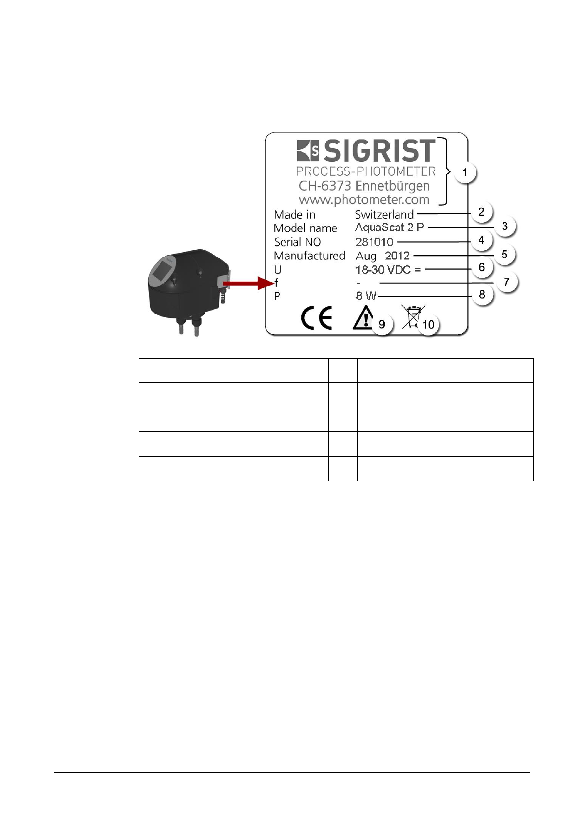
2.2 Identification of the photometer
The rating plate below is located on the connection box:
Figure 2: AquaScat 2 P
Manufacturer
Country of origin
Product name
Serial number
Date of manufacture
Service voltage
Frequency range
Power
Observe the Instruction Manual
Disposal information

Instrument overview Instruction Manual AquaMaster
12746E/4 13
2.3 Identification of the connection box
The rating plate below is located on the connection box:
Figure 3: AquaMaster rating plate, connection box
Manufacturer
Country of origin
Product name
Serial number
Date of manufacture
Service voltage
Frequency range
Power
Observe the Instruction Manual
Disposal information
Instruction Manual AquaMaster Instrument overview
14 12746E/4
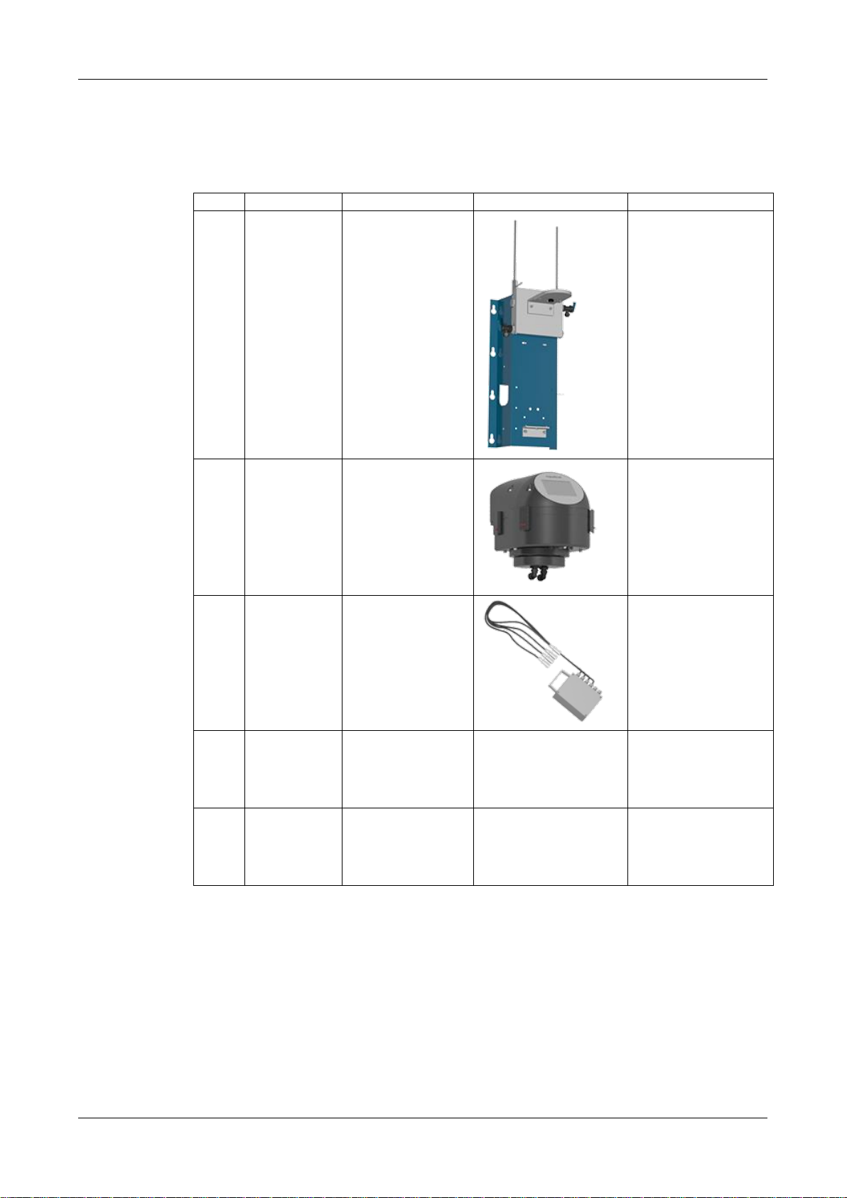
2.4 Scope of supply and accessory parts
Standard scope of supply for AquaMaster 119493:
PCS.
ART. NO.
NAME
VIEW
VARIANT
1
Included in
scope of
supply of the
119493.
Wall bracket com-
plete with measur-
ing cell block.
1
118995
Included in
scope of
supply of the
119493.
Photometer
AquaScat 2 P with
integrated
I/O module
1
Included in
scope of
supply of the
119493.
Connection box
with all cables.
1
Included in
scope of
supply of the
119493.
Wash bottle
1
Included in
scope of
supply of the
119493.
Beaker

Instrument overview Instruction Manual AquaMaster
12746E/4 15
PCS.
ART. NO.
NAME
VIEW
VARIANT
1
Instruction Manual
German
French
English
1
Reference hand-
book
German
English
1
Brief Instructions
German
French
English
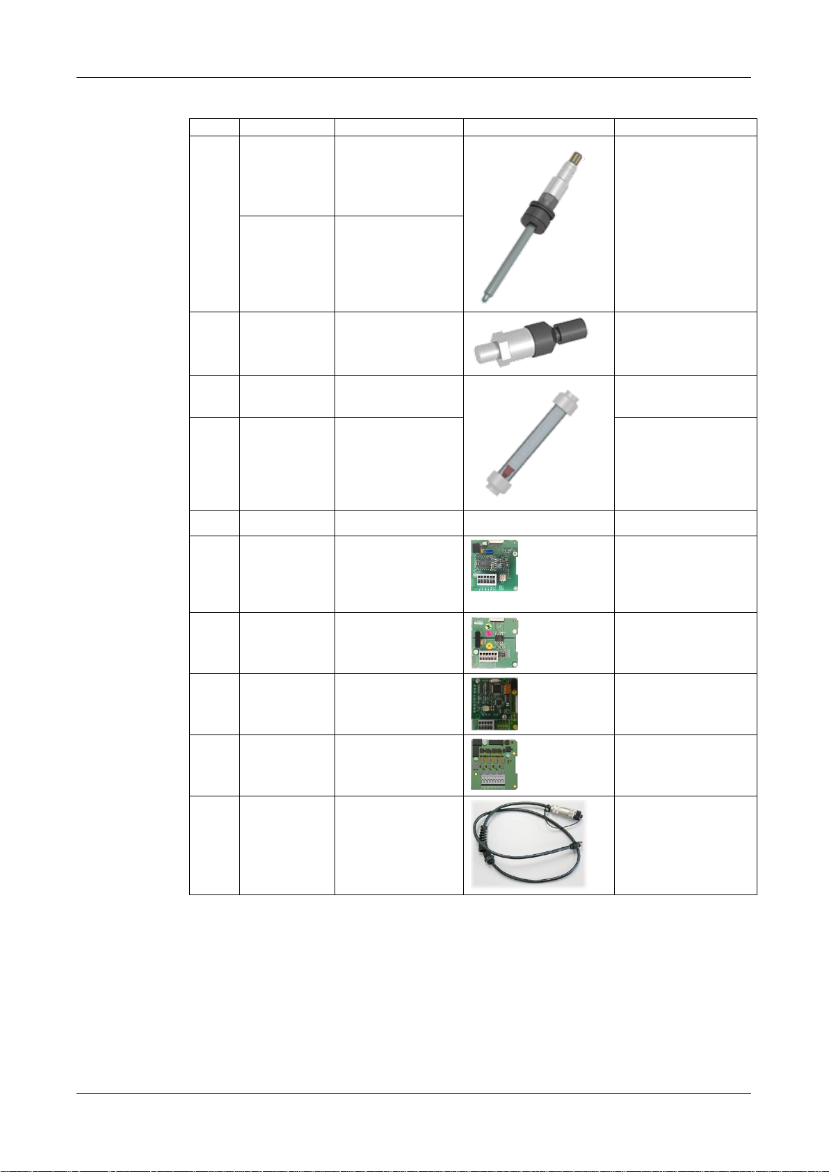
Optional accessory parts:
PCS.
ART. NO.
NAME
VIEW
VARIANT
1
116706
Checking unit for
AquaScat 2 P
1
119498
Conductivity sen-
sor
Sensor for measur-
ing conductivity.
Conducell 4USF
Arc 120
119509
Conductivity
standard 147μ/cm,
500 ml
1
119495
pH sensor
Sensor for measur-
ing the pH value.
Polilyte Plus Arc 120
Two calibration
solutions are stand-
ardly supplied. If no
specific specifications
are made, they are
pH 4 and pH 7.
Calibration stan-
dards:
119506
pH 7
119507
pH 10
119571
pH 4
1
119497
Oxygen sensor
Sensor for measur-
ing dissolved oxy-
gen.
VisiFerm DO Arc 120
Instruction Manual AquaMaster Instrument overview
16 12746E/4
PCS.
ART. NO.
NAME
VIEW
VARIANT
1
119496
Redox sensor
Sensor for measur-
ing the redox
potential.
Polilyte Plus ORP
Arc 120
119508
Redox buffer
475 mV, 500 ml
1
119499
Pressure sensor
1
119709
Flow meter with
regulating valve
With push-in fitting
10 mm
1
119710
Flow meter with
limit switch &
regulating valve
With push-in fitting
10 mm
1
119566
Regulating valve
1
119102
Profibus DP inter-
face print
Reference
handbook
1
119103
Modbus RTU inter-
face print Ref-
erence handbook
1
119798
HART interface
print Reference
handbook
1
119041
Current output 4-
way module
1
119081
Ethernet cable
IP66
(for fixed installa-
tion)
Instrument overview Instruction Manual AquaMaster
12746E/4 17
2.5 AquaMaster technical data
DATA
VALUES
Sample media
Water
Dimensions
ca. 55 x 115 x 40 cm (B x H x T)
Service voltage
100 .. 240 VAC, 47 .. 63 Hz or 18 .. 30 VDC
Power consumption
10W AquaMaster + 4 Sensors
25W AquaMaster + 4 Sensors + optional Photometer
Weight
ca.16 kg
Protection class
IP 54
Maximum operating
altitude
No limitation when powered with 24 VDC, also the relay voltages
do not exceed 24 V.
2000 m (6600 ft.) above sea level, if powered with 250 V.
Ambient temperature
0 .. +50 °C
Ambient humidity
0 .. 100 % rel. humidity, noncondensing
Sample pressure
0.6 MPa (6 bar)

Instruction Manual AquaMaster Instrument overview
18 12746E/4
Technical data of the AquaScat 2 P:
DATA
VALUES
Measuring principle
Scattered light measurement
Measurement span
0 .. 100 FNU
Wavelength
880 nm, compliant with DIN EN ISO 7027
Radiation class
LED device of Class 1 according to EN 60825-1
Measuring angle
90°
Resolution
0.001 FNU
Reproducibility
0-10 FNU: ±0.002 FNU or ±1% full scale
10-100 FNU: ±1.5 %
Repeatability
0.001 FNU or ±0.1% full scale
Outputs/Inputs
Outputs:
4 x 0/4 .. 20 mA, galvanically isolated to max. 50 V relative to
ground and max. load 500 Ω
5 x digital outputs up to max. 30 VDC, freely configurable
Optional: With an integrated 4-way current output, four addi-
tional outputs (0/4 to 20 mA, also galvanically isolated) are
available
2 relay contacts 250 V, 4 A
Inputs:
4 x digital inputs up to max. 30 VDC, freely configurable
Limit contact for the flow meter
2 x current inputs up to max. 25 mA
Measuring ranges
8 ranges between 0 .. 0.1 and 0 .. 100 FNU freely configurable
Digital communication
and logger
Ethernet, Modbus TCP, micro SD card (for logging, SW-
update, diagnosis)
Optional: Interfaces for Profibus DP, Modbus RTU or HART
Display
¼ VGA with touchscreen
Resolution: 320 x 240 pixels with 3.5“ diagonal
Instrument overview Instruction Manual AquaMaster
12746E/4 19
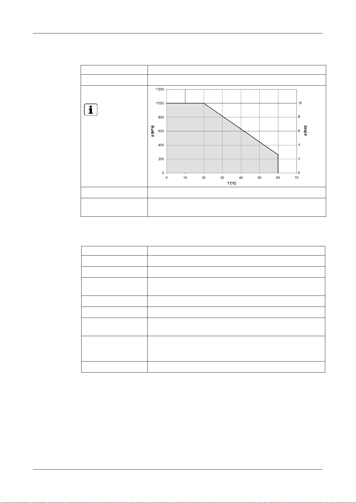
Technical data of the closed measuring cell:
DATA
VALUES
Material
POM/PVC
Sample pressure/-
temperatur
The grey area
corresponds to the
permitted working
range.
Sample flow
0.2 .. 2 l/min
Connections
Plastic push-in 10 mm
GF-System: Outer threads G3/4“
Conductivity sensor (Conducell 4USF Arc 120):
DATA
VALUES
Sensor type
Conductivity
Measuring principle
4-pin measurement
Measuring values
Conductivity: µS/cm, mS/cm
Temperature: °C, °K, °F
Measuring range
1 .. 300,000 µS/cm
Operating temperature
-20 .. 130 °C
Accuracy
± 3% at 1 µS/cm .. 100 mS/cm
± 5% at 100 .. 300 mS/cm
Medium-contacting
material
1.4435/316L; Ra < 0.4 µm (N5)
PEEK (FDA approved)
EPDM (FDA approved)
Various
Autoclavable, can be sterilized with steam, suitable for CIP

Instruction Manual AquaMaster Instrument overview
20 12746E/4
pH sensor (Polilyte Plus Arc 120):
DATA
VALUES
Sensor type
pH
Measuring principle
Potential measurement compared to reference
Measuring values
pH
Temperature: °C, °K, °F
Measuring range
pH 0 .. 14
Operating temperature
0 .. 130 °C
Accuracy
± 0.05
Medium-contacting
material
Glass, FPM (Viton),
Electrolyte: Polisolve Plus,
Reference: Everref-L
min. conductivity of
the sample
2 µS/cm
Various
Autoclavable, can be sterilized with steam
Sensor Redox/ORP (Polilyte Plus ORP Arc 120):
DATA
VALUES
Sensor type
Redox/ORP
Measuring principle
Potential measurement
Measuring values
ORP: mV
Temperature: °C, °K, °F
Measuring range
-1500 .. 1500 mV
Operating temperature
0 .. 130 °C
Medium-contacting
material
Glass, FPM (Viton), platinum
Various
Autoclavable, can be sterilized with steam
Table of contents
Popular Measuring Instrument manuals by other brands


YOKOGAWA
YOKOGAWA AQ6373B Getting started guide

LaserLiner
LaserLiner ClimaHome-Check operating instructions

Klein Tools
Klein Tools VDV500-123 Probe-Pro instruction manual

Navman
Navman FUEL 2100 Installation and operation manual

Hubner
Hubner FG 2 Series Operating and assembly instructions

METER
METER AQUALAB 3 quick start