Navman FUEL 2100 User manual

NAVMAN
Installation and
Operation Manual
www.navman.com
FUEL 2100
English .............3
Français .........11
Español ..........19
Deutsch .......... 27
Nederlands .... 35
Svenska ......... 43
Suomi .............51

FUEL 2100 Installation and Operation ManualNAVMAN
2
FCC Statement
Note: This equipment has been tested and found to comply with the limits for a Class B
digital device, pursuant to Part 15 of the FCC Rules. These limits are designed to
provide reasonable protection against harmful interference in a normal installation. This
equipment generates, uses and can radiate radio frequency energy and, if not installed
and used in accordance with the instructions, may cause harmful interference to radio
communications. However, there is no guarantee that interference will not occur in a
particular installation. If this equipment does cause harmful interference to radio or
television reception, which can be determined by turning the equipment off and on, the
user is encouraged to try to correct the interference by one or more of the following
measures:
Reorient or relocate the receiving antenna.
Increase the separation between the equipment and receiver.
Connect the equipment into an output on a circuit different from that to which the
receiver is connected.
Consult the dealer or an experienced technician for help.
A shielded cable must be used when connecting a peripheral to the serial ports.

3
FUEL 2100 Installation and Operation Manual
NAVMAN
Contents
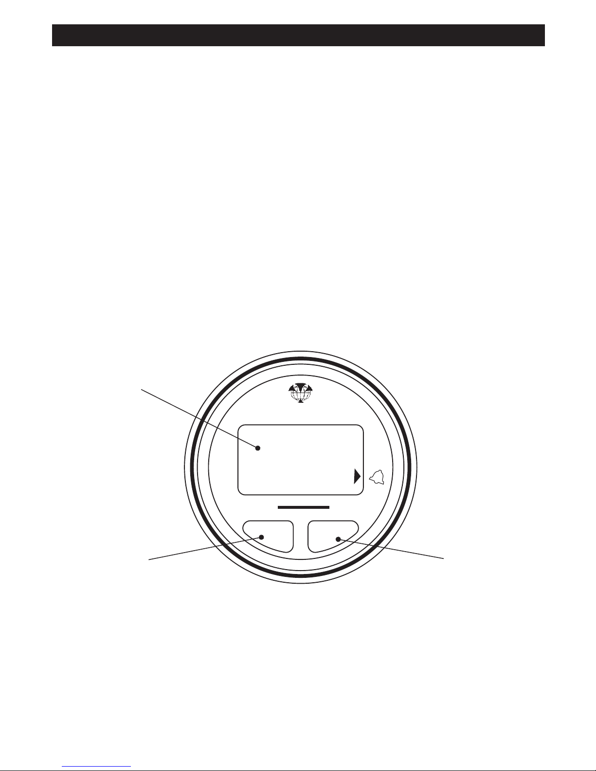
1 Operation ......................................................................................................... 4
FuelFlow ........................................................................................................................... 4
OtherFuel Functions ......................................................................................................... 4
Changingthefuelremainingvalue ..................................................................................... 4
Settingthe lowfuel alarm................................................................................................... 5
Alarmactivation ................................................................................................................. 5
Resetting theTRIP LOG or the TOTALLOG ..................................................................... 5
2 Instrument Setup ............................................................................................. 6
Selectingunitsof measure................................................................................................. 6
Calibration ......................................................................................................................... 6
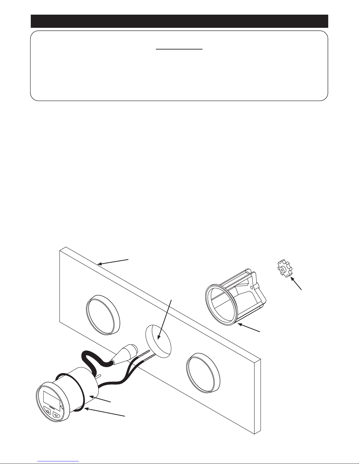
3 Installation ....................................................................................................... 7
Location ............................................................................................................................. 7
Mounting ........................................................................................................................... 7
WiringConnection ............................................................................................................. 8
Installationofthefuelflowtransducer ................................................................................ 8
Appendix A - Specifications .............................................................................. 9
Appendix B - Troubleshooting Chart.............................................................. 10
Appendix C - How to contact us ..................................................................... 59
It is the owner’s sole responsibility to install and use the instrument and transducer/s in a manner that will
notcauseaccidents,personalinjury or property damage.The user of this productis solely responsible for
observing safe boating practices.
NAVMAN NZ LIMITED DISCLAIMSALLLIABILITY FORANYUSE OF THIS PRODUCTINAWAYTHAT
MAY CAUSEACCIDENTS, DAMAGE OR THAT MAYVIOLATE THE LAW.
This manual represents the FUEL2100 as at the time of printing. Navman NZ Limited reserves the right
to make changes to specifications without notice.
GoverningLanguage:This statement,anyinstruction manuals,user guidesand otherinformation relating
to the product (Documentation) may be translated to, or has been translated from, another language
(Translation). In the event of any conflict between any Translation of the Documentation, the English
language version of the Documentation will be the official version of the Documentation.
Copyright©2002NavmanNZLimited,NewZealand.Allrightsreserved.NAVMANisaregisteredtrademark
of Navman NZ Limited.
Important

FUEL 2100 Installation and Operation ManualNAVMAN
4
FuelFlow
Press the key to display the current fuel flow
rate.
TOTALFLOW
^V
OtherFuel Functions
Press the key to cycle through the possible
functions.Eachtimethe keyispressedthedisplay
willshowan identifierfor 2seconds beforethe value
is displayed.
Fuel used on trip
TOTAL
V
tOt
Fuel used in total
TOTAL
V
ALr
Low fuel alarm setting
GAS
TOTAL
V
Fuel remaining in tank
Changingthefuelremaining value
To change the value of fuel remaining in the tank,
press the key until the display indicates for
two seconds and then displays the current value.
TOTALFLOW
^V
Press and hold both keys for three seconds and the
displayed value will begin to flash.
Press and hold for 3 seconds
260
Use the and keys to change the value. Press
and hold both keys for one second to save this new
valuetomemoryandtoexit thisfunction.Thedisplay
will indicate and then the new value.
1 Operation
#
"

5
FUEL 2100 Installation and Operation Manual
NAVMAN
Setting the low fuel alarm
Usethe keytoselect thealarmfunction.The LCD
willindicate
ALr
fortwosecondsandwillthendisplay
the present alarm value. If no alarm value has been
entered the LCD will indicate
0FF
.
TOTALFLOW
^V
ALr
012 0FF
Press and hold both keys for three seconds and the
displayed value will begin to flash.
Press and hold for 3 seconds
812
Use the and keys to select the desired alarm
value. Press and hold both keys for one second to
savethisnewvaluetomemoryandtoexitthisfunction.
Thedisplaywillindicate
ALr
andthenthenew value.
ALr
814
#
Thearrowpointing atthealarm bellwillbe activated.
Alarmactivation
Ifthefuelremainingvalue dropsbelowthe fuelalarm
value, the alarm will sound and the alarm arrow will
flash.
12 #
Press any key to mute the alarm. The alarm arrow
will continue to flash as long as the alarm condition
remains.
Resetting the TRIP LOG or
the TOTAL LOG
To reset a log, press the key until the display
indicates the name of the log to be reset.
Pressandhold bothkeys forthree seconds.Display
willshow
trP
or
tOt
for2 secondsbeforeresetting
to zero.
Press and hold for 3 seconds
000
trP tOt
Thetrip log value may be reset withoutchanging
the total log value.
If the total log is reset to zero, then the trip log
will automatically reset to zero.
Note :
If the total log exceeds 999 then both it
and the trip log will be reset to zero.

FUEL 2100 Installation and Operation ManualNAVMAN
6
Selecting units of measure
The FUEL 2100 will indicate fuel values in Litres,
ImperialgallonsorUSgallons.Tochangethecurrent
setting perform the following steps:
1. Power up the unit while holding down the
key.
TOTALFLOW
^V
Hold down during power up
2. When the unit is on, release the key. The
display will indicate the current display unit with:
Imperial Gallons
US Gallons
Litres
3. To select the display unit desired, use the
and keys to change the value.
4. To exit this mode, press and hold both the
and keys simultaneously for one second.
Press and hold to exit
Information will now be indicated in the selected
display unit.
Calibration
Thefueltransducer suppliedwith thefuel flowmeter
will provide readings at better than 5% accuracy.
Individual calibration will increase this level of
accuracy to better than 2% over a fuel flow range of
10.0to120 litresper hour. Usethe followingstepsto
calibrate your fuel flow meter:
1. Reset the total log value to zero (see previous
page).
2. Use a known amount of fuel. The larger the
amount the more accurate the calibration will
be.
3. Take note of the actual volume of fuel used and
the fuel used indicated by the total log. If these
two totals are different the instrument may
require calibration.
4. Press and hold the key while applying power
Hold down during power up
5. Release the key. Display will flash current
total log value.
260
6. Use the or keys to make the display
indicate the actual volume of fuel used.
7. Press both keys simultaneously for 1 sec to
exit.
Press and hold for 1 second
The fuel flow meter is now calibrated.
2 Instrument Setup
FLOW
^

7
FUEL 2100 Installation and Operation Manual
NAVMAN
Mounting
The instrument panel must be 3mm to 19mm
(1/8" to 3/4") in thickness.
• Drill a 51mm (2") hole in the instrument panel.
• Remove brackets and insert the instrument so
the back is flush with the instrument panel.
• Slide the bracket over the instrument and
tighten the mounting nut until secure.
Instrument
Panel
Mounting
Bracket
Mounting Nut
Instrument
51mm (2”)
Hole
Sealing
Gasket
WARNING
ITISVERYIMPORTANTTOINSTALLAFUELFILTER BETWEENTHE FUELFLOWTRANSDUCER
AND THE FUEL TANK. THIS FILTER WILL CATCH LARGER PARTICLES OF DIRT FROM THE
FUELTANKANDPREVENTTHEFINEGAUZE FILTERINTHE FUELFLOWTRANSDUCER FROM
BECOMINGBLOCKEDASTHIS MAYDAMAGETHE ENGINE.
Location
TheFUEL2100isdesignedforaboveor belowdeck
installation. Select a position that is:
• On a flat surface
• At least 300mm (12") from a compass
• At least 500mm (20") from any radio
• Easy to read by the helmsman and crew
• Protected from physical damage
• Accessible to electrical cable connections
3 Installation

FUEL 2100 Installation and Operation ManualNAVMAN
8
WiringConnection
• Keep electrical and transducer cables away
from alternator or other noise generating
electrical cables. Avoid connecting the
instrument to power circuits that share loads
with ignition, alternators, inverters and radio
transmitters. Electrical power supply
connections should always be as short as
possible.
600mm (24”)
POWER CORD
BRACKET
BUZZER
RED
(+) TERMINAL BLACK
(-) TERMINAL
FUJI 5-PIN
CONNECTOR
• Connect the red wire to the positive supply via
a 1 amp fuse or a 1 amp circuit breaker.
Connect the black wire to the electrical ground.
• Connect the fuel flow transducer to the five pin
transducer inlet cable.
Installation of the fuel flow
transducer
The fuel flow transducer is designed for installation
in Coast Guard approved 9.5 mm
(3/8”) flexible fuel line. The transducer MUST be
installed AFTER the main fuel filter. It should be
located well away from any area where it will be
effected by excessive heat or vibration from the
engine. It is preferable to mount the transducer in a
vertical position.
Drain all the fuel from the flexible fuel line. Cut the
fuelline and usingthe fuel hosefixing clipsprovided
install the transducerso thattheFUELINside of the
transducer connects to the fuel tank.

9
FUEL 2100 Installation and Operation Manual
NAVMAN
• Size
Mount 51mm diameter hole
Depth behind face plate 95mm max.
Display 3-character LCD
• Colour
Black with texture on bezel.
• Backlighting
Red coloured diffused lighting for display.
• Water Integrity
Front will withstand direct water spray.
• Alarm
Audio and visual alarm indicates remaining fuel
total has dropped below a preset alarm value.
• Flow
2.5 to 160 litres per hour
0.5 to 43 US gallons per hour
0.4 to 36 imperial gallons per hour
• Logs
Logs record fuel used up to 999 display units.
Total Log is saved in memory at power down.
Both Trip Log andTotal Log can be reset via the
keypad.
• Fuel Remaining
User enters a fuel value into memory via the key
pad. The quantity of fuel used is automatically
subtracted from this total. This value remains in
memory at power down.
• Operating Voltage
8 V DC to 16.5 V DC.
• Operating Temperature
0 to 50°C (32 to 122°F).
• Current Drain
70mA max.
• RF Interference
<6 dB quieting on any marine radio channel
(with 3 dB gain antenna) within one metre of the
instrument. Complies with CE EMC standards
EN50081-1and EN50082-1.
TOTALFLOW
888
^V
FUELPower
NAVMAN
Change Value Down
Display is backlit for
Night Operation
Change Value Up
Appendix A - Specifications

FUEL 2100 Installation and Operation ManualNAVMAN
10
No display:
1. Check DC power connections and DC polarity with voltmeter.
2. Check fuse.
No flow reading indicated:
1. Check connection to flow transducer.
2. Remove transducer from fuel line, blow through transducer, a whistling noise will indicate the
turbine is rotating.
Low flow reading indicated:
1. Check that the gauze filter is clean. If the filter is not installed fine strands may clog up the
turbine.
2. Check calibration is correct.
High or erratic reading:
Check fuel connections are well made. Air in fuel lines will cause erratic or high readings.
Appendix B - Troubleshooting Chart

NORTH AMERICA
NAVMAN USA INC.
18 Pine St. Ext.
Nashua, NH 03060.
Ph: +1 603 577 9600
e-mail: [email protected]
OCEANIA
New Zealand
Absolute Marine Ltd.
Unit B, 138 Harris Road,
East Tamaki, Auckland.
Ph: +64 9 273 9273
e-mail:
Papua New Guinea
Lohberger Engineering
Lawes Road, Konedobu
PO Box 810
Port Moresby
Ph: +675 321 2122
e-mail: [email protected]
Australia
NAVMAN AUSTRALIA PTY
Limited
Unit 6 / 5-13 Parsons St,
Rozelle, NSW 2039, Australia.
Ph: +61 2 9818 8382
e-mail: [email protected]
SOUTH AMERICA
Argentina
Costanera UNO S.A.
Av Presidente R Castillo y
Calle 13
1425 Buenos Aires, Argentina.
Ph: +54 11 4312 4545
e-mail:
Website:
www.costanerauno.ar
Brazil
REALMARINE
Estrada do Joa 3862,
CEP2611-020,
Barra da Tijuca, Rio de Janeiro,
Brasil.
Ph: +55 21 2483 9700
e-mail:
vendas@marinedepot.com.br
Equinautic Com Imp Exp de
Equip Nauticos Ltda.
Av. Diario de Noticias 1997 CEP
90810-080, Bairro Cristal, Porto
Alegre - RS, Brasil.
Ph: +55 51 3242 9972
e-mail:
equinautic@equinautic.com.br
ASIA
China
Peaceful Marine Electronics Co. Ltd.
Hong Kong, Guangzhou,
Shanghai, Qindao, Dalian.
E210, Huang Hua Gang Ke Mao
Street, 81 Xian Lie Zhong Road,
510070 Guangzhou, China.
Ph: +86 20 3869 8784
e-mail:[email protected]
Website:www.peaceful-marine.com
India
Access India Overseas Pvt
A-98, Sector 21, Noida, India
Ph: +91 120 244 2697
e-mail: [email protected]
Indonesia
Polytech Nusantara
Graha Paramita 2nd Floor
Jln Denpasar Raya Blok D2
Kav 8 Kuningan, Jakarta 12940
Tel: 021 252 3249
Korea
Kumhomarine Technology Co., Ltd.
#604-842, 2F, 1118-15,
Janglim1-Dong, Saha-Gu
Busan, Korea
Ph: +82 51 293 8589
e-mail: [email protected]
Website: www.kumhomarine.com
Maldives
Maizan Electronics Pte. Ltd.
8 Sosunmagu Male
Ph: +960 78 2444
e-mail:
Singapore
RIQ PTE Ltd.
81, Defu Lane 10, Hah Building,
#02-00 Singapore 539217
Ph: +65 6741 3723
e-mail: riq@postone.com
Taiwan
Seafirst International Corporation
No.281, Hou-An Road
Chien-Chen Dist.
Kaohsiung, Taiwan R.O.C.
Ph: +886 7 831 2688
e-mail: [email protected]
Thailand
Thong Electronics (Thailand)
Company Ltd.
923/588 Thaprong Road,
Mahachai,
Muang, Samutsakhon 74000,
Thailand.
Ph: +66 34 411 919
e-mail: [email protected]
Vietnam
Haidang Co. Ltd.
16A/A1E, Ba thang hai St.
District 10, Hochiminh City.
Ph: +84 8 86321 59
e-mail: [email protected]
Website: www.haidangvn.com
MIDDLE EAST
Lebanon and Syria
Letro, Balco Stores,
Moutran Street, Tripoli VIA Beirut.
Ph: +961 6 624512
e-mail: [email protected]
United Arab Emirates
Kuwait, Oman, Iran & Saudi Arabia
Abdullah Moh’d Ibrahim
Trading, opp Creak Rd.
Baniyas Road, Dubai.
Ph: +971 4 229 1195
e-mail: [email protected]
AFRICA
South Africa
Pertec (Pty) Ltd Coastal,
Division No.16 Paarden Eiland Rd.
Paarden Eiland, 7405
Postal Address: PO Box 527,
Paarden Eiland 7420
Cape Town, South Africa.
Ph: +27 21 511 5055
e-mail: [email protected]
EUROPE
France, Belgium and
Switzerland
PLASTIMO INTERNATIONAL
15, rue Ingénieur Verrière,
BP435,
56325 Lorient Cedex.
Ph: +33 2 97 87 36 36
e-mail: [email protected]
Website: www.plastimo.fr
Germany
PLASTIMO DEUTSCHLAND
15, rue Ingénieur Verrière
BP435- 56325 Lorient Cedex.
Ph: +49 6105 92 10 09
+49 6105 92 10 10
+49 6105 92 10 12
e-mail:
Website: www.plastimo.de
Italy
PLASTIMO ITALIA
Nuova Rade spa, Via del Pontasso 5
I-16015 CASELLA SCRIVIA (GE).
Ph: +39 1096 8011
e-mail: [email protected]
Website: www.plastimo.it
Holland
PLASTIMO HOLLAND BV.
Industrieweg 4-6,
2871 RP SCHOONHOVEN.
Ph: +31 182 320 522
e-mail: [email protected]
Website: www.plastimo.nl
United Kingdom
PLASTIMO Mfg. UK Ltd.
School Lane - Chandlers Ford
Industrial Estate,
EASTLEIGH - HANTS S053 ADG.
Ph: +44 23 8026 3311
e-mail: [email protected]
Website: www.plastimo.co.uk
Sweden, Denmark or Finland
PLASTIMO NORDIC AB.
Box 28 - Lundenvägen 2,
47321 HENAN.
Ph: +46 304 360 60
e-mail: [email protected]
Website: www.plastimo.se
Spain
PLASTIMO ESPAÑA, S.A.
Avenida Narcís Monturiol, 17
08339 VILASSAR DE DALT,
(Barcelona).
Ph: +34 93 750 75 04
e-mail: [email protected]
Website: www.plastimo.es
Portugal
PLASTIMO PORTUGAL
Avenida de India N°40
1300-299 Lisbon
Ph: +351 21 362 04 57
e-mail:
Other countries in Europe
PLASTIMO INTERNATIONAL
15, rue Ingénieur Verrière
BP435
56325 Lorient Cedex, France.
Ph: +33 2 97 87 36 59
e-mail:
Website: www.plastimo.com
REST OF WORLD /
MANUFACTURERS
Navman NZ Limited
13-17 Kawana St. Northcote.
P.O. Box 68 155 Newton,
Auckland, New Zealand.
Ph: +64 9 481 0500
e-mail:
Website: www.navman.com
Appendix C - How to contact us www.navman.com.

Lon 174° 44.535’E
Lat 36° 48.404’S
Made in New Zealand
MN000207A
FUEL 2100
NAVMAN
Table of contents
Other Navman Measuring Instrument manuals

Navman
Navman A300 Sport.Tool User manual

Navman
Navman R300 User manual

Navman
Navman Repeat 3100 User manual

Navman
Navman WIND 3100 User manual

Navman
Navman SPEED 2100 User manual

Navman
Navman MULTI 3100 User manual

Navman
Navman S300 User manual

Navman
Navman A300 Sport.Tool User manual

Navman
Navman Qube 300 User manual

Navman
Navman WIND 3150 User manual