SIHGA PICK User manual

Instruction for load attechment PICK
Original
Product name:Pick
Product group: Load attachment
Drawing number: B-00223
Serial numbers: ……………………………………………….
Year of Manufacture: .............……..
SIHGA®PICK

2 Operating Instruction Pick www.sihga.com
SIHGA®GmbH I Gewerbepark Kleinreith 4
•A- 4694 Ohlsdorf bei Gmunden
•Tel +43 7612-74370-0
•Fax +43 7612-74370-10
•E-Mail [email protected]
SECURITY IN WOOD CONSTRUCTION GUARANTEES EXTRAORDINARY RESULTS
www.sihga.com
Contents
1 Foreword............................................................................................................................3
2 Safety information..............................................................................................................4
2.1 General safety information...........................................................................................4
2.2 Prerequisites for use ....................................................................................................4
3 Correct use.........................................................................................................................4
3.1 Lifting process ..............................................................................................................4
3.2 Lifting gear....................................................................................................................5
3.3 Wood..............................................................................................................................5
3.4 Drill hole........................................................................................................................5
3.5 Cross laminated timber................................................................................................5
3.6 Solid wood / glue laminated timber .............................................................................5
3.7 Storage........................................................................................................................ ..5
3.8 Accessories...................................................................................................................5
4 Incorrect use ......................................................................................................................6
5 Information about use........................................................................................................6
5.1 Cross laminated timber edge distances.......................................................................6
5.2 Solid wood edge distances............................................................................................6
5.3 Load specifications .......................................................................................................7
6 Using the Pick ..................................................................................................................30
6.1 Attaching.................................................................................................................................30
6.2 Loosening ...............................................................................................................................30
7 Tests.................................................................................................................................31
7.1 Testing before initial commissioning..........................................................................31
7.2 Testing before starting work.......................................................................................31
7.3 Testing / Maintenance.................................................................................................31
8 Annex ...............................................................................................................................32
8.1 Declaration of conformity ...........................................................................................32
8.2 Component name / Spare parts list ...........................................................................33
8.3 Delivery condition........................................................................................................33
8.4 Pick Safty Inspection ..................................................................................................34
8.5 Maintenance log..........................................................................................................36

www.sihga.com Operating Instruction Pick 3
SIHGA®GmbH I Gewerbepark Kleinreith 4
•A- 4694 Ohlsdorf bei Gmunden
•Tel +43 7612-74370-0
•Fax +43 7612-74370-10
•E-Mail [email protected]
SECURITY IN WOOD CONSTRUCTION GUARANTEES EXTRAORDINARY RESULTS
www.sihga.com
1 Foreword
Dear Customer,
You have chosen a Pick, many thanks for your trust in us.
With your new Pick you have chosen a load attachment with proven engineering for numerous applications.
These operating instructions must be carefully read by all users before the first commissioning so that you
get to know your Pick quickly and comprehensively. In this document you will find all the information about
the application, expert checking and maintenance. Your care helps to prevent dangers, reduces repair costs
and down times and increases the reliability and life of the product. If you have any questions or problems
with your Pick, please contact us at SIHGA®GmbH.
These operating instructions are part of the Pick, always keep them close by or store them in the system
case.
In addition to the operating instructions and any accident prevention regulations operating in the country of
use, the acknowledged standards for safe and professional work must also be observed. National statutory
conditions shall have priority over the information provided in these operating instructions.
Producing and forwarding these operating instructions to third parties is only permitted with our consent.
We hope you enjoy the advantages of your Pick.
Yours sincerely,
Your specialist for fastening technology in wood construction SIHGA®GmbH

4 Operating Instruction Pick www.sihga.com
SIHGA®GmbH I Gewerbepark Kleinreith 4
•A- 4694 Ohlsdorf bei Gmunden
•Tel +43 7612-74370-0
•Fax +43 7612-74370-10
•E-Mail [email protected]
SECURITY IN WOOD CONSTRUCTION GUARANTEES EXTRAORDINARY RESULTS
www.sihga.com
2 Safety information
The following safety information must be observed in all cases:
2.1 General safety information
a) The maximum load-bearing capacities stated take safety factors into account according to EN 13155:2009.
b) All persons, who work with the Pick, must know and observe the safety information in the operating
instructions.
c) The manufacturer is not liable for damage arising from non-compliance with the instructions.
d) The Pick has been designed in accordance with the recognised technical safety regulations. However, in
the event of non-compliance with the operating and safety instructions during use, dangers can arise,
which may lead to irreversible injuries or death.
e) If possible, perform a listening test during the lifting process. If there are „cracking noises“, the load must
immediately be placed on the floor and must no longer be raised.
f) Every time a load is lifted, perform a sight inspection as to whether the Pick has a force-locking
connection with the component or has slipped out.
g) With regard to the risk of injury, safety gloves and PSE must be used according to the occupational health
and safety requirements.
h) Warranty and liability claims due to personal injury or material damage are excluded in the event of the
operating instructions being disregarded.
2.2 Prerequisites for use
a) For an appropriate test before first use (Section 7.1)
b) For correct use (Section 3)
c) Use of authorised expert personnel
d) For the specified angles and loads (according to Section 5)
e) For fault-free Pick
f) For successful tests (Section 7.2 and 7.3)
g) Up to 20,000 load changes
3 Correct use
The load attachment exclusively serves the lifting of glue laminated, cross laminated and solid timber carriers (hereinafter referred
to as components) made from spruce, fir, pine and larch. Timber with very strong resin content, such as pine and larch, and grain-cut
attached walls may only be lifted at an angle of ≥ 5° to the drill hole axis and with multiple lines. Only one component may be raised per
lift. The correct use is specified below.
3.1 Lifting process
a) The duration of the lifting process may not be more than a reasonable period for the loading and unloading
process.
b) Use of the Pick and manipulation of the load may be performed exclusively by trained and qualified expert
personnel.
c) Before lifting a component, always ensure that there are no tools or other loose parts on the component.
d) The lifted goods must always be transported slowly and carefully.
e) The load-bearing capacity stated on the device is the maximum load that may be attached. However,
depending on the application, the maximum load must correspond to the load chart in Section 5.3. The
angle of the loading direction in the respective applications must be observed.
f) Standing under a suspended load is not permitted.
g) The user may only start to move a load when they are convinced that the load has been attached correctly.
h) When hanging the Pick, the user must ensure that the Pick can be operated such that the user is not at
risk either from the device itself or from the carrier or the load.
i) The Pick can work in an ambient temperature between –10°C and +80°C. For work under extreme
conditions, the manufacturer should be consulted.
j) The Pick must not come into contact with salt or chlorine.
k) If longer components are transported, the use of two or four Picks is recommended in order to prevent
pendulum movements.
l) The accident prevention and safety requirements for the Pick of the respective country where the Pick is

www.sihga.com Operating Instruction Pick 5
SIHGA®GmbH I Gewerbepark Kleinreith 4
•A- 4694 Ohlsdorf bei Gmunden
•Tel +43 7612-74370-0
•Fax +43 7612-74370-10
•E-Mail [email protected]
SECURITY IN WOOD CONSTRUCTION GUARANTEES EXTRAORDINARY RESULTS
www.sihga.com
used must be observed.
m) Do not leave loads in a raised or tightened condition beyond the period of the manipulation procedure.
n) The combination of several Picks is only permitted on one surface of the component.
o) In the event of malfunctions, the Pick must immediately be switched off.
3.2 Lifting gear
a) Only suitable lifting gear may be used.
3.3 Wood
a) The component to be lifted may have a wood moisture content of 10 to 20%.
b) The component must be free from cracks and loose knots in in a radius of 25 cm around the drill hole.
c) For components with a supporting effect when installed, the drill holes must be arranged according to
statics and if necessary must be omitted.
3.4 Drill hole
a) The drill hole must have a diameter of 50 mm -0,0/+1,0 mm tolerance and a depth of at least 70 mm.
b) The drill hole must be clean and protected against weathering influences such as frost, rain and snow.
c) The drill hole must not have any coating, paints or greases.
d) The Pick must be countersunk to the stop of the base ring in the drill hole.The downside of the base ring must rest on
the entire surface.
e) The drill hole must not be used for lifting more than six times.
f) The drill hole axis must always be aligned less than 90° to the surface of the component.
g) The drill hole may only be drilled by a qualified person. The quality of the drill hole must be checked before lifting.
h) The drill hole needs to have appropriate quality otherwise the hole needs to be drilled again on site.
3.5 Cross laminated timber
a) The edge distances according to Section 5.1 must be observed.
b) For grain-cut drill holes in cross laminate timber panels, the end-grain proportion must be max. 40 mm.
3.6 Solid wood / Glue laminated timber
a) The axis of a drill hole in solid wood must not be less than 90° to the direction of grain.
b) The material thickness of the component to be lifted must not be less than 6 cm.
c) The carrier width must not be less than 8 cm.
3.7 Storage
a) To prevent corrosion, the Pick must exclusively be stored dry.
b) If the Pick is exposed to moisture, it must be ensured that the Pick is dried as quickly as possible. In
particular, the inner mechanics must be checked.
c) The Pick must be stored at all times so that damage to the Pick and injuries to persons are prevented.
(Use of the supplied system case is recommended).
d) The Pick must be protected from dirt.
3.8 Accessories
a) The supplied shackle DIN EN 13889 (bow shackle with eye bolts) may only be replaced by an equivalent.
The minimum load-bearing capacity of the load attachment must never be undercut. The threaded
securing bolt must be used.
b) It is recommended that the supplied auger is used for the precise creation of the drill hole.
6 Operating Instruction Pick www.sihga.com
SIHGA®GmbH I Gewerbepark Kleinreith 4
•A- 4694 Ohlsdorf bei Gmunden
•Tel +43 7612-74370-0
•Fax +43 7612-74370-10
•E-Mail [email protected]
SECURITY IN WOOD CONSTRUCTION GUARANTEES EXTRAORDINARY RESULTS
www.sihga.com
4 Incorrect use
a) The load-bearing capacity of the load attachment must not be exceeded.
b) No changes may be made to the Pick or its technical documentation.
c) The use of the Pick to transport persons is prohibited.
d) When transporting the load, pendulum movements and collisions with barriers must be avoided.
e) Do not let the Pick fall.
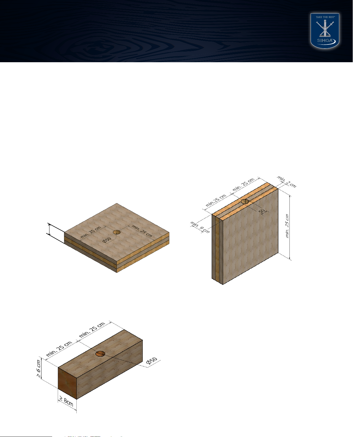
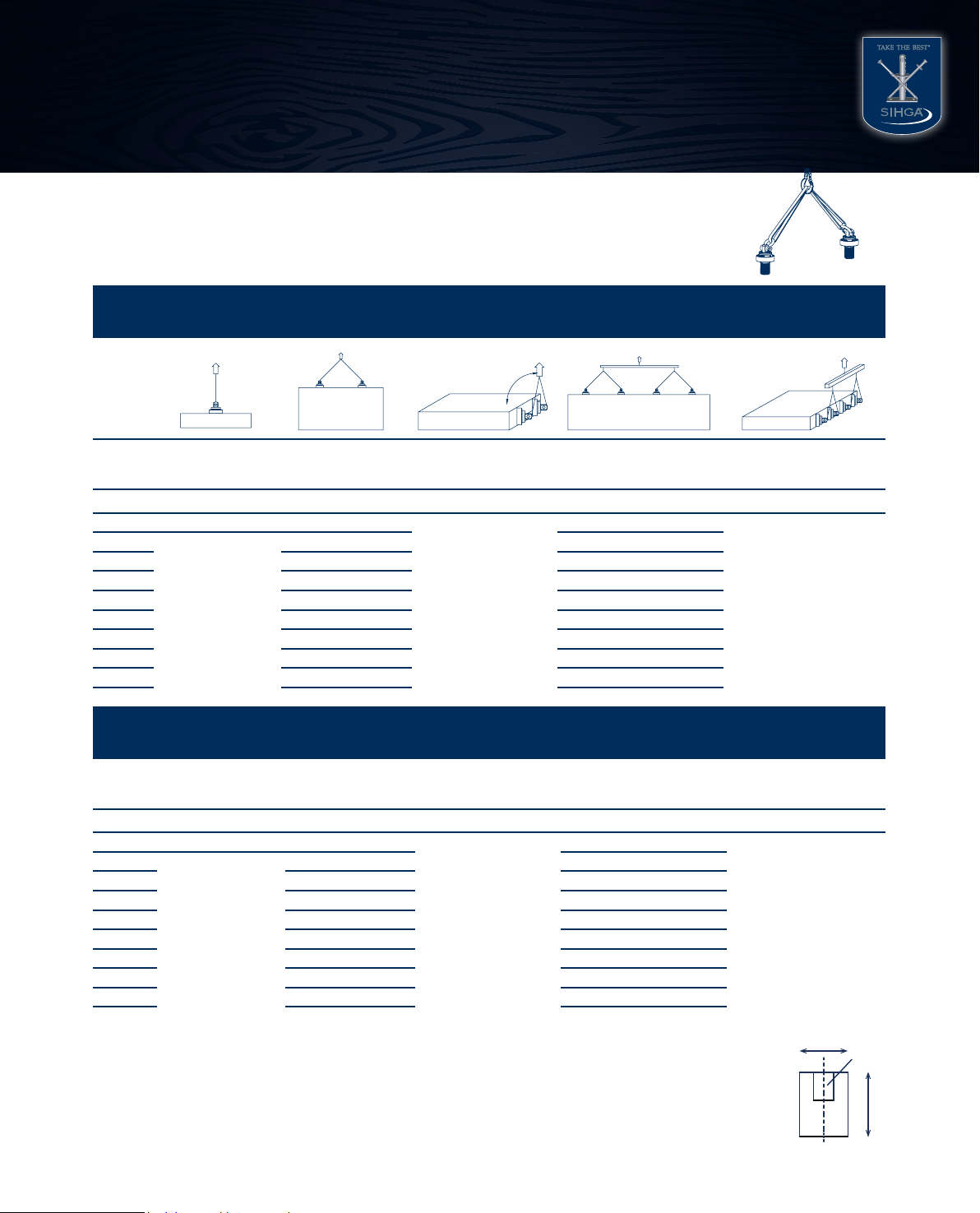
5 Information about use
5.1 Cross laminated timber edge distances
5.2 Solid timber edge distances
Horizontal Manipulation of cross laminated
timber
Vertical Manipulation of cross laminated
timber
Horizontal Manipulation of glue laminated and solid timber
min. 9cm for lower layer in visual quality
min 7 cm for concealed lower layer
www.sihga.com Operating Instruction Pick 7
SIHGA®GmbH I Gewerbepark Kleinreith 4
•A- 4694 Ohlsdorf bei Gmunden
•Tel +43 7612-74370-0
•Fax +43 7612-74370-10
•E-Mail [email protected]
SECURITY IN WOOD CONSTRUCTION GUARANTEES EXTRAORDINARY RESULTS
www.sihga.com
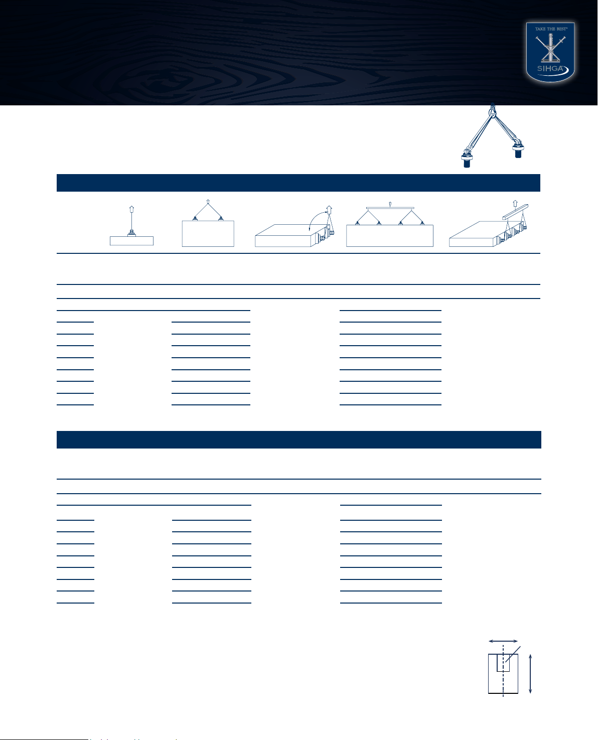
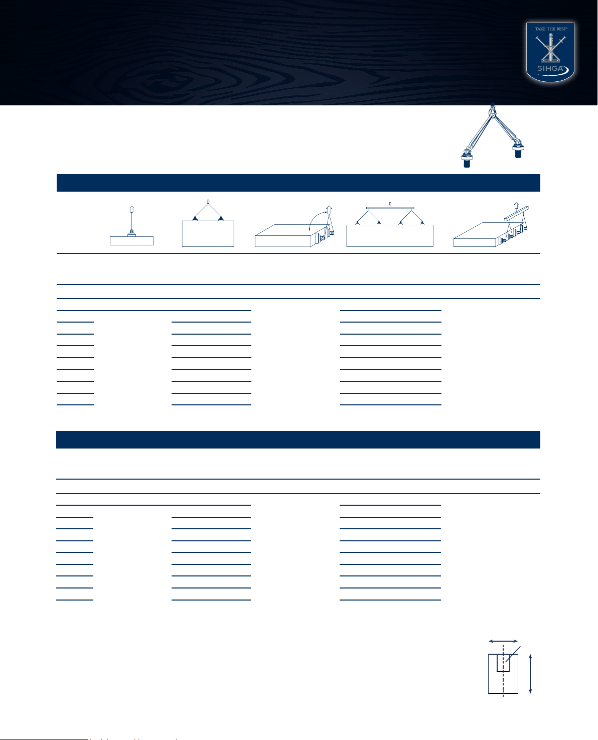
5.3 Load specifications
load specification for framework walls ≥ 8/6 head plate [min.b x h x l = 8 x 6 x 50]
angle° 1 attachment
point* 2 attachment points 2 attachment points
slewing
2 x 2 attachemtent points
with traverse sling and
spreader
2 x 2 attachment points
slewing with traverse
sling and spreader
[kg total weight] [kg total weight] [kg total weight] [kg total weight] [kg total weight]
0 506 1012
693
not permitted
1386
5 939 1879
10 867 1733
15 794 1588
20 721 1443
25 649 1297
30 576 1152
35 503 1007
40 431 861
45 358 716
90°
load specification for framework walls ≥ 10/6 head plate [min.b x h x l = 10 x 6 x 50]
angle° 1 attachment
point* 2 attachment points 2 attachment points
slewing
2 x 2 attachemtent points
with traverse sling and
spreader
2 x 2 attachment points
slewing with traverse
sling and spreader
[kg total weight] [kg total weight] [kg total weight] [kg total weight] [kg total weight]
0 623 1246
693
not permitted
1386
5 1210 2420
10 1174 2349
15 1139 2277
20 1103 2206
25 1067 2134
30 1031 2063
35 996 1991
40 960 1920
45 924 1848
traverse sling
= 0° = 45°
*Highly resinous timber like pine and larch or walls, mounted at the front side, may only be lifted at an angle of ≥ 5° to the borehole axis and with 2
attachment points.
The minimum distance to the surface layer while fastening plates at the front face is min. 2 cm.
The minimum distance between each attachment point equals 50 cm.
The minimum distance between attachment points and beam and plate edge may not be smaller than 25 cm.
Attention: the distance of the posts at framework walls ist not permitted to be larger than 62,5 cm.
The operator is responsible for sufficient power transfer from head plate to posts. SIHGA takes on no liability.
max. = total weight /2 max. = total weight/2
b
h
drill hole

8 Operating Instruction Pick www.sihga.com
SIHGA®GmbH I Gewerbepark Kleinreith 4
•A- 4694 Ohlsdorf bei Gmunden
•Tel +43 7612-74370-0
•Fax +43 7612-74370-10
•E-Mail [email protected]
SECURITY IN WOOD CONSTRUCTION GUARANTEES EXTRAORDINARY RESULTS
www.sihga.com
load specification for framework walls ≥ 14/6 head plate [min.b x h x l = 14 x 6 x 50]
angle° 1 attachment
point* 2 attachment points 2 attachment points
slewing
2 x 2 attachemtent points
with traverse sling and
spreader
2 x 2 attachment points
slewing with traverse
sling and spreader
[kg total weight] [kg total weight] [kg total weight] [kg total weight] [kg total weight]
0 900 1800
947
not permitted
1894
5 1752 3504
10 1704 3409
15 1657 3313
20 1609 3218
25 1561 3122
30 1513 3027
35 1466 2931
40 1418 2836
45 1370 2740
90°
load specification for framework walls ≥ 10/8 head plate [min.b x h x l = 10 x 8 x 50]
angle° 1 attachment
point* 2 attachment points 2 attachment points
slewing
2 x 2 attachemtent points
with traverse sling and
spreader
2 x 2 attachment points
slewing with traverse
sling and spreader
[kg total weight] [kg total weight] [kg total weight] [kg total weight] [kg total weight]
0 660 1320
960
not permitted
1920
5 1278 2556
10 1236 2472
15 1194 2388
20 1152 2304
25 1110 2220
30 1068 2136
35 1026 2052
40 984 1968
45 942 1884
= 0° = 45°
traverse sling
*Highly resinous timber like pine and larch or walls, mounted at the front side, may only be lifted at an angle of ≥ 5° to the borehole axis and with 2
attachment points.
The minimum distance to the surface layer while fastening plates at the front face is min. 2 cm.
The minimum distance between each attachment point equals 50 cm.
The minimum distance between attachment points and beam and plate edge may not be smaller than 25 cm.
Attention: the distance of the posts at framework walls ist not permitted to be larger than 62,5 cm.
The operator is responsible for sufficient power transfer from head plate to posts. SIHGA takes on no liability.
max. = total weight /2 max. = total weight/2
b
h
drill hole

www.sihga.com Operating Instruction Pick 9
SIHGA®GmbH I Gewerbepark Kleinreith 4
•A- 4694 Ohlsdorf bei Gmunden
•Tel +43 7612-74370-0
•Fax +43 7612-74370-10
•E-Mail [email protected]
SECURITY IN WOOD CONSTRUCTION GUARANTEES EXTRAORDINARY RESULTS
www.sihga.com
load specification for framework walls ≥ 14/8 head plate [min.b x h x l = 14 x 8 x 50]
angle° 1 attachment
point* 2 attachment points 2 attachment points
slewing
2 x 2 attachemtent points
with traverse sling and
spreader
2 x 2 attachment points
slewing with traverse
sling and spreader
[kg total weight] [kg total weight] [kg total weight] [kg total weight] [kg total weight]
0 900 1800
1500
not permitted
3000
5 1752 3504
10 1704 3409
15 1657 3313
20 1609 3218
25 1561 3122
30 1513 3027
35 1466 2931
40 1418 2836
45 1370 2740
load specification for framework walls ≥ 8/10 head plate [min.b x h x l = 8 x 10 x 50]
angle° 1 attachment
point* 2 attachment points 2 attachment points
slewing
2 x 2 attachemtent points
with traverse sling and
spreader
2 x 2 attachment points
slewing with traverse
sling and spreader
[kg total wight] [kg total wight] [kg total wight] [kg total wight] [kg total wight]
0 660 1320
827
not permitted
1654
5 1280 2559
10 1239 2478
15 1199 2397
20 1158 2316
25 1118 2236
30 1077 2155
35 1037 2074
40 996 1993
45 956 1912
90°
= 0° = 45°
traverse sling
*Highly resinous timber like pine and larch or walls, mounted at the front side, may only be lifted at an angle of ≥ 5° to the borehole axis and with 2
attachment points.
The minimum distance to the surface layer while fastening plates at the front face is min. 2 cm.
The minimum distance between each attachment point equals 50 cm.
The minimum distance between attachment points and beam and plate edge may not be smaller than 25 cm.
Attention: the distance of the posts at framework walls ist not permitted to be larger than 62,5 cm.
The operator is responsible for sufficient power transfer from head plate to posts. SIHGA takes on no liability.
max. = total weight /2 max. = total weight/2
b
h
drill hole
10 Operating Instruction Pick www.sihga.com
SIHGA®GmbH I Gewerbepark Kleinreith 4
•A- 4694 Ohlsdorf bei Gmunden
•Tel +43 7612-74370-0
•Fax +43 7612-74370-10
•E-Mail [email protected]
SECURITY IN WOOD CONSTRUCTION GUARANTEES EXTRAORDINARY RESULTS
www.sihga.com
*Highly resinous timber like pine and larch or walls, mounted at the front side, may only be lifted at an angle of ≥ 5° to the borehole axis and with 2
attachment points.
The minimum distance to the surface layer while fastening plates at the front face is min. 2 cm.
The minimum distance between each attachment point equals 50 cm.
The minimum distance between attachment points and beam and plate edge may not be smaller than 25 cm.
Attention: the distance of the posts at framework walls ist not permitted to be larger than 62,5 cm.
The operator is responsible for sufficient power transfer from head plate to posts. SIHGA takes on no liability.
load specification for framework walls ≥ 10/10 head plate [min.b x h x l = 10 x 10 x 50]
angle° 1 attachment
point* 2 attachment points 2 attachment points
slewing
2 x 2 attachemtent points
with traverse sling and
spreader
2 x 2 attachment points
slewing with traverse
sling and spreader
[kg total weight] [kg total weight] [kg total weight] [kg total weight] [kg total weight]
0 827 1654
947
not permitted
1894
5 1580 3160
10 1506 3013
15 1433 2865
20 1359 2718
25 1285 2570
30 1211 2423
35 1138 2275
40 1064 2128
45 990 1980
load specification for framework walls ≥ 12/10 head plate [min.b x h x l = 12 x 10 x 50]
angle° 1 attachment
point* 2 attachment points 2 attachment points
slewing
2 x 2 attachemtent points
with traverse sling and
spreader
2 x 2 attachment points
slewing with traverse
sling and spreader
[kg total wight] [kg total wight] [kg total wight] [kg total wight] [kg total wight]
0 870 1740
1160
not permitted
2320
5 1657 3313
10 1573 3147
15 1490 2980
20 1407 2813
25 1323 2647
30 1240 2480
35 1157 2313
40 1073 2147
45 990 1980
90°
= 0° = 45°
traverse sling
max. = total weight /2 max. = total weight/2
b
h
drill hole

www.sihga.com Operating Instruction Pick 11
SIHGA®GmbH I Gewerbepark Kleinreith 4
•A- 4694 Ohlsdorf bei Gmunden
•Tel +43 7612-74370-0
•Fax +43 7612-74370-10
•E-Mail [email protected]
SECURITY IN WOOD CONSTRUCTION GUARANTEES EXTRAORDINARY RESULTS
www.sihga.com
load specification for framework walls ≥ 14/10 head plate [min.b x h x l = 14 x 10 x 50]
angle° 1 attachment
point* 2 attachment points 2 attachment points
slewing
2 x 2 attachemtent points
with traverse sling and
spreader
2 x 2 attachment points
slewing with traverse
sling and spreader
[kg total weight] [kg total weight] [kg total weight] [kg total weight] [kg total weight]
0 870 1740
1547
not permitted
3094
5 1685 3370
10 1630 3260
15 1575 3149
20 1520 3039
25 1464 2929
30 1409 2819
35 1354 2708
40 1299 2598
45 1244 2488
90°
load specification for framework walls ≥ 14/20 head plate [min.b x h x l = 14 x 20 x 50]
angle° 1 attachment
point* 2 attachment points 2 attachment points
slewing
2 x 2 attachemtent points
with traverse sling and
spreader
2 x 2 attachment points
slewing with traverse
sling and spreader
[kg total weight] [kg total weight] [kg total weight] [kg total weight] [kg total weight]
0 1250 2500
1547
not permitted
3094
5 2374 4749
10 2249 4498
15 2123 4247
20 1998 3996
25 1872 3744
30 1747 3493
35 1621 3242
40 1496 2991
45 1370 2740
= 0° = 45°
traverse sling
*Highly resinous timber like pine and larch or walls, mounted at the front side, may only be lifted at an angle of ≥ 5° to the borehole axis and with 2
attachment points.
The minimum distance to the surface layer while fastening plates at the front face is min. 2 cm.
The minimum distance between each attachment point equals 50 cm.
The minimum distance between attachment points and beam and plate edge may not be smaller than 25 cm.
Attention: the distance of the posts at framework walls ist not permitted to be larger than 62,5 cm.
The operator is responsible for sufficient power transfer from head plate to posts. SIHGA takes on no liability.
max. = total weight /2 max. = total weight/2
b
h
drill hole

12 Operating Instruction Pick www.sihga.com
SIHGA®GmbH I Gewerbepark Kleinreith 4
•A- 4694 Ohlsdorf bei Gmunden
•Tel +43 7612-74370-0
•Fax +43 7612-74370-10
•E-Mail [email protected]
SECURITY IN WOOD CONSTRUCTION GUARANTEES EXTRAORDINARY RESULTS
www.sihga.com
Load table for poles ø = min. 16 cm l = min. 50 cm rod
Angle ° 1 attachment
point*
2 attachment point
lifting
2 attachment points,
uprighting
2 x 2 attachment points
using belt and crossbeam
2 x 2 attachment points,
uprighting using belt and
crossbeam
[kg total weight] [kg total weight] [kg total weight] [kg total weight] [kg total weight]
0 887 1774
-
not permitted
-
5 1675 3350
10 1576 3152
15 1477 2953
20 1378 2755
25 1278 2557
30 1179 2359
35 1080 2160
40 981 1962
45 882 1764
*Highly resinous timber like pine and larch, or frontally mounted walls, may only be lifted at an angle of ≥ 5° to the borehole axis, and using multiple
attachment points.
The minimum distance to the surface layer of the top layer while mounting at the front face of the plywood board is min. 2 cm
The minimum distance between each attachment point equals 50 cm
The minimum distance between attachment points and beam and plate edge may not be less than 25 cm
Caution: The axis-to-centre distance between the vertical members for timber-framed walls cannot be more than 62.5 cm.
The operator is responsible for sufficient force transfer from the upper beam (plate) to the vertical members, SIHGA®does not accept liability for this.
b
h
Bohrloch
90°
Load table for Pollmeier S beech wood grain side ≥ 8/12 [min.w x h x l = 8 x 12 x 50] rod
Angle ° 1 attachment
point*
2 attachment point
lifting
2 attachment points,
uprighting
2 x 2 attachment points
using belt and crossbeam
2 x 2 attachment points,
uprighting using belt and
crossbeam
[kg total weight] [kg total weight] [kg total weight] [kg total weight] [kg total weight]
0 1250 2500
-
not permitted
-
5 2405 4811
10 2311 4621
15 2216 4432
20 2121 4243
25 2027 4053
30 1932 3864
35 1837 3675
40 1743 3485
45 1648 3296
= 0° = 45° max = total weight/2 max = total weight/2
traverse sling

www.sihga.com Operating Instruction Pick 13
SIHGA®GmbH I Gewerbepark Kleinreith 4
•A- 4694 Ohlsdorf bei Gmunden
•Tel +43 7612-74370-0
•Fax +43 7612-74370-10
•E-Mail [email protected]
SECURITY IN WOOD CONSTRUCTION GUARANTEES EXTRAORDINARY RESULTS
www.sihga.com
Load table for Kerto®S joint side ≥ 7.5/12 [min.w x h x l = 7.5 x 12 x 50] rod
Angle ° 1 attachment
point*
2 attachment point
lifting
2 attachment points,
uprighting
2 x 2 attachment points
using belt and crossbeam
2 x 2 attachment points,
uprighting using belt and
crossbeam
[kg total weight] [kg total weight] [kg total weight] [kg total weight] [kg total weight]
0 713 1426
-
not permitted
-
5 1376 2752
10 1326 2652
15 1276 2552
20 1226 2452
25 1176 2352
30 1126 2252
35 1076 2152
40 1026 2052
45 976 1952
*Highly resinous timber like pine and larch, or frontally mounted walls, may only be lifted at an angle of ≥ 5° to the borehole axis, and using multiple
attachment points.
The minimum distance to the surface layer of the top layer while mounting at the front face of the plywood board is min. 2 cm
The minimum distance between each attachment point equals 50 cm
The minimum distance between attachment points and beam and plate edge may not be less than 25 cm
Caution: The axis-to-centre distance between the vertical members for timber-framed walls cannot be more than 62.5 cm.
The operator is responsible for sufficient force transfer from the upper beam (plate) to the vertical members, SIHGA®does not accept liability for this.
b
h
Bohrloch
90°
Load table for Kerto®S joint side ≥ 9/12 [min.w x h x l = 9 x 12 x 50] rod
Angle ° 1 attachment
point*
2 attachment point
lifting
2 attachment points,
uprighting
2 x 2 attachment points
using belt and crossbeam
2 x 2 attachment points,
uprighting using belt and
crossbeam
[kg total weight] [kg total weight] [kg total weight] [kg total weight] [kg total weight]
0 813 1626
-
not permitted
-
5 1566 3132
10 1506 3013
15 1447 2893
20 1387 2774
25 1327 2654
30 1267 2535
35 1208 2415
40 1148 2296
45 1088 2176
= 0° = 45° max = total weight/2 max = total weight/2
traverse sling

14 Operating Instruction Pick www.sihga.com
SIHGA®GmbH I Gewerbepark Kleinreith 4
•A- 4694 Ohlsdorf bei Gmunden
•Tel +43 7612-74370-0
•Fax +43 7612-74370-10
•E-Mail [email protected]
SECURITY IN WOOD CONSTRUCTION GUARANTEES EXTRAORDINARY RESULTS
www.sihga.com
Load table for frontal wood attachment (only GLH) ≥10/10 [min.w x h x l = 10 x 10 x 50]
Angle ° 1 attachment point* 2 attachment point lifting 2 attachment points,
uprighting
2 attachment points, lifting
at less than 90°
[kg total weight] [kg total weight] [kg total weight] [kg total weight]
0 not permitted not permitted
427 213
5 840
10 766
15 692
20 617
25 543
30 469
35 395
40 320
45 246
*Highly resinous timber like pine and larch, or frontally mounted walls, may only be lifted at an angle of ≥ 5° to the borehole axis, and using multiple
attachment points.
The minimum distance to the surface layer of the top layer while mounting at the front face of the plywood board is min. 2 cm
The minimum distance between each attachment point equals 50 cm
The minimum distance between attachment points and beam and plate edge may not be less than 25 cm
b
h
Bohrloch
90°
Load table for frontal wood attachment (only GLH) ≥ 16/16 [min.w x h x l = 16 x 16 x 50]
Angle ° 1 attachment point* 2 attachment point lifting 2 attachment points,
uprighting
2 attachment points, lifting
at less than 90°
[kg total weight] [kg total weight] [kg total weight] [kg total weight]
0 not permitted not permitted
1427 713
5 1460
10 1343
15 1226
20 1109
25 992
30 875
35 758
40 641
45 524
= 0° = 45° max = total weight/2 = 90°
traverse sling
www.sihga.com Operating Instruction Pick 15
SIHGA®GmbH I Gewerbepark Kleinreith 4
•A- 4694 Ohlsdorf bei Gmunden
•Tel +43 7612-74370-0
•Fax +43 7612-74370-10
•E-Mail [email protected]
SECURITY IN WOOD CONSTRUCTION GUARANTEES EXTRAORDINARY RESULTS
www.sihga.com
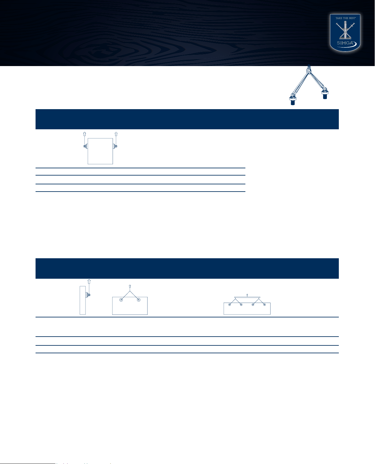
Load table for cross laminated timber boards wall panels laterally to the front surface,
fastened 15 cm from the edge [min.w x l x d = 50 x 50 x 9]
Angle ° 2 attachment point lifting 2 attachment points, uprighting
[kg total weight] [kg total weight]
90 660 660
= 90°
*Highly resinous timber like pine and larch, or frontally mounted walls, may only be lifted at an angle of ≥ 5° to the borehole axis, and using multiple
attachment points.
The minimum distance to the surface layer of the top layer while mounting at the front face of the plywood board is min. 2 cm
The minimum distance between each attachment point equals 50 cm
The minimum distance between attachment points and beam and plate edge may not be less than 25 cm
Load table for cross laminated timber boards wall panels laterally to the surface,
fastened 15 cm from the edge [min.w x l x d = 50 x 50 x 9]
Angle ° 1 attachment
point*
2 attachment point
lifting
2 attachment points,
uprighting
2 x 2 attachment points
using belt and crossbeam
2 x 2 attachment points,
uprighting using belt and
crossbeam
[kg total weight] [kg total weight] [kg total weight] [kg total weight] [kg total weight]
90 577 1154 1154 2308 2308
= 90°
traverse sling

16 Operating Instruction Pick www.sihga.com
SIHGA®GmbH I Gewerbepark Kleinreith 4
•A- 4694 Ohlsdorf bei Gmunden
•Tel +43 7612-74370-0
•Fax +43 7612-74370-10
•E-Mail [email protected]
SECURITY IN WOOD CONSTRUCTION GUARANTEES EXTRAORDINARY RESULTS
www.sihga.com
Load table for timber-framed walls ≥ 10/4.5 upper threshold [min.w x h x l = 10 x 4.5 x 50]
Angle ° 1 attachment
point*
2 attachment point
lifting
2 attachment points,
uprighting
2 x 2 attachment points
using belt and crossbeam
2 x 2 attachment points,
uprighting using belt and
crossbeam
[kg total weight] [kg total weight] [kg total weight] [kg total weight] [kg total weight]
0 250 500
500
not permitted
1000
5 500 1000
10 500 1000
15 500 1000
20 500 1000
25 500 1000
30 500 1000
35 500 1000
40 500 1000
45 500 1000
*Highly resinous timber like pine and larch, or frontally mounted walls, may only be lifted at an angle of ≥ 5° to the borehole axis, and using multiple
attachment points.
The minimum distance to the surface layer of the top layer while mounting at the front face of the plywood board is min. 2 cm
The minimum distance between each attachment point equals 50 cm
The minimum distance between attachment points and beam and plate edge may not be less than 25 cm
Caution: The axis-to-centre distance between the vertical members for timber-framed walls cannot be more than 62.5 cm.
The operator is responsible for sufficient force transfer from the upper beam (plate) to the vertical members, SIHGA®does not accept liability for this.
b
h
Bohrloch
90°
Load table for timber-framed walls ≥ 12/4.5 upper threshold [min.w x h x l = 12 x 4.5 x 50]
Angle ° 1 attachment
point*
2 attachment point
lifting
2 attachment points,
uprighting
2 x 2 attachment points
using belt and crossbeam
2 x 2 attachment points,
uprighting using belt and
crossbeam
[kg total weight] [kg total weight] [kg total weight] [kg total weight] [kg total weight]
0 487 974
720
not permitted
1440
5 931 1861
10 887 1775
15 844 1688
20 801 1601
25 757 1515
30 714 1428
35 671 1341
40 627 1255
45 584 1168
= 0° = 45° max = total weight/2 max = total weight/2
traverse sling

www.sihga.com Operating Instruction Pick 17
SIHGA®GmbH I Gewerbepark Kleinreith 4
•A- 4694 Ohlsdorf bei Gmunden
•Tel +43 7612-74370-0
•Fax +43 7612-74370-10
•E-Mail [email protected]
SECURITY IN WOOD CONSTRUCTION GUARANTEES EXTRAORDINARY RESULTS
www.sihga.com
Load table for timber-framed walls ≥ 16/4.5 upper threshold [min.w x h x l = 16 x 4.5 x 50]
Angle ° 1 attachment
point*
2 attachment point
lifting
2 attachment points,
uprighting
2 x 2 attachment points
using belt and crossbeam
2 x 2 attachment points,
uprighting using belt and
crossbeam
[kg total weight] [kg total weight] [kg total weight] [kg total weight] [kg total weight]
0 500 1000
1000
not permitted
2000
5 958 1915
10 915 1830
15 873 1745
20 830 1660
25 788 1576
30 745 1491
35 703 1406
40 660 1321
45 618 1236
*Highly resinous timber like pine and larch, or frontally mounted walls, may only be lifted at an angle of ≥ 5° to the borehole axis, and using multiple
attachment points.
The minimum distance to the surface layer of the top layer while mounting at the front face of the plywood board is min. 2 cm
The minimum distance between each attachment point equals 50 cm
The minimum distance between attachment points and beam and plate edge may not be less than 25 cm
Caution: The axis-to-centre distance between the vertical members for timber-framed walls cannot be more than 62.5 cm.
The operator is responsible for sufficient force transfer from the upper beam (plate) to the vertical members, SIHGA®does not accept liability for this.
b
h
Bohrloch
90°
Load table for timber-framed walls ≥ 8/3.9 upper threshold Kerto®Q
[min.w x h x l = 8 x 3.9 x 50]
Angle ° 1 attachment
point*
2 attachment point
lifting
2 attachment points,
uprighting
2 x 2 attachment points
using belt and crossbeam
2 x 2 attachment points,
uprighting using belt and
crossbeam
[kg total weight] [kg total weight] [kg total weight] [kg total weight] [kg total weight]
0 160 320
320
not permitted
608
5 304 608
10 288 575
15 271 543
20 255 510
25 239 478
30 223 445
35 206 413
40 190 380
45 174 348
= 0° = 45°
traverse sling

18 Operating Instruction Pick www.sihga.com
SIHGA®GmbH I Gewerbepark Kleinreith 4
•A- 4694 Ohlsdorf bei Gmunden
•Tel +43 7612-74370-0
•Fax +43 7612-74370-10
•E-Mail [email protected]
SECURITY IN WOOD CONSTRUCTION GUARANTEES EXTRAORDINARY RESULTS
www.sihga.com
Load table for timber-framed walls ≥ 12/3.9 upper threshold Kerto®Q
[min.w x h x l = 12 x 3.9 x 50]
Angle ° 1 attachment
point*
2 attachment point
lifting
2 attachment points,
uprighting
2 x 2 attachment points
using belt and crossbeam
2 x 2 attachment points,
uprighting using belt and
crossbeam
[kg total weight] [kg total weight] [kg total weight] [kg total weight] [kg total weight]
0 300 600
600
not permitted
1143
5 572 1143
10 543 1086
15 515 1029
20 486 972
25 458 916
30 429 859
35 401 802
40 372 745
45 344 688
*Highly resinous timber like pine and larch, or frontally mounted walls, may only be lifted at an angle of ≥ 5° to the borehole axis, and using multiple
attachment points.
The minimum distance to the surface layer of the top layer while mounting at the front face of the plywood board is min. 2 cm
The minimum distance between each attachment point equals 50 cm
The minimum distance between attachment points and beam and plate edge may not be less than 25 cm
Caution: The axis-to-centre distance between the vertical members for timber-framed walls cannot be more than 62.5 cm.
The operator is responsible for sufficient force transfer from the upper beam (plate) to the vertical members, SIHGA®does not accept liability for this.
b
h
Bohrloch
90°
Load table for timber-framed walls ≥ 16/3.9 upper threshold Kerto®Q
[min.w x h x l = 16 x 3.9 x 50]
Angle ° 1 attachment
point*
2 attachment point
lifting
2 attachment points,
uprighting
2 x 2 attachment points
using belt and crossbeam
2 x 2 attachment points,
uprighting using belt and
crossbeam
[kg total weight] [kg total weight] [kg total weight] [kg total weight] [kg total weight]
0 300 600
600
not permitted
1188
5 594 1188
10 588 1176
15 582 1164
20 576 1152
25 570 1140
30 564 1128
35 558 1116
40 552 1104
45 546 1092
= 0° = 45° max = total weight/2 max = total weight/2
traverse sling
www.sihga.com Operating Instruction Pick 19
SIHGA®GmbH I Gewerbepark Kleinreith 4
•A- 4694 Ohlsdorf bei Gmunden
•Tel +43 7612-74370-0
•Fax +43 7612-74370-10
•E-Mail [email protected]
SECURITY IN WOOD CONSTRUCTION GUARANTEES EXTRAORDINARY RESULTS
www.sihga.com
Load table for timber-framed walls ≥ 8/5.7 upper threshold Kerto®Q
[min.w x h x l = 8 x 5.7 x 50]
Angle ° 1 attachment
point*
2 attachment point
lifting
2 attachment points,
uprighting
2 x 2 attachment points
using belt and crossbeam
2 x 2 attachment points,
uprighting using belt and
crossbeam
[kg total weight] [kg total weight] [kg total weight] [kg total weight] [kg total weight]
0 260 520
520
not permitted
1015
5 507 1015
10 495 989
15 482 964
20 469 939
25 457 913
30 444 888
35 431 863
40 419 837
45 406 812
*Highly resinous timber like pine and larch, or frontally mounted walls, may only be lifted at an angle of ≥ 5° to the borehole axis, and using multiple
attachment points.
The minimum distance to the surface layer of the top layer while mounting at the front face of the plywood board is min. 2 cm
The minimum distance between each attachment point equals 50 cm
The minimum distance between attachment points and beam and plate edge may not be less than 25 cm
Caution: The axis-to-centre distance between the vertical members for timber-framed walls cannot be more than 62.5 cm.
The operator is responsible for sufficient force transfer from the upper beam (plate) to the vertical members, SIHGA®does not accept liability for this.
b
h
Bohrloch
90°
Load table for timber-framed walls ≥ 12/5.7 upper threshold Kerto®Q
[min.w x h x l = 12 x 5.7 x 50]
Angle ° 1 attachment
point*
2 attachment point
lifting
2 attachment points,
uprighting
2 x 2 attachment points
using belt and crossbeam
2 x 2 attachment points,
uprighting using belt and
crossbeam
[kg total weight] [kg total weight] [kg total weight] [kg total weight] [kg total weight]
0 490 980
980
not permitted
1904
5 952 1904
10 924 1849
15 897 1793
20 869 1738
25 841 1682
30 813 1627
35 786 1571
40 758 1516
45 730 1460
= 0° = 45° max = total weight/2 max = total weight/2
traverse sling

20 Operating Instruction Pick www.sihga.com
SIHGA®GmbH I Gewerbepark Kleinreith 4
•A- 4694 Ohlsdorf bei Gmunden
•Tel +43 7612-74370-0
•Fax +43 7612-74370-10
•E-Mail [email protected]
SECURITY IN WOOD CONSTRUCTION GUARANTEES EXTRAORDINARY RESULTS
www.sihga.com
traverse sling
Load table for timber-framed walls ≥ 16/5.7 upper threshold Kerto®Q
[min.w x h x l = 16 x 5.7 x 50]
Angle ° 1 attachment
point*
2 attachment point
lifting
2 attachment points,
uprighting
2 x 2 attachment points
using belt and crossbeam
2 x 2 attachment points,
uprighting using belt and
crossbeam
[kg total weight] [kg total weight] [kg total weight] [kg total weight] [kg total weight]
0 750 1500
1500
not permitted
2880
5 1440 2880
10 1380 2761
15 1321 2641
20 1261 2522
25 1201 2402
30 1141 2283
35 1082 2163
40 1022 2044
45 962 1924
*Highly resinous timber like pine and larch, or frontally mounted walls, may only be lifted at an angle of ≥ 5° to the borehole axis, and using multiple
attachment points.
The minimum distance to the surface layer of the top layer while mounting at the front face of the plywood board is min. 2 cm
The minimum distance between each attachment point equals 50 cm
The minimum distance between attachment points and beam and plate edge may not be less than 25 cm
Caution: The axis-to-centre distance between the vertical members for timber-framed walls cannot be more than 62.5 cm.
The operator is responsible for sufficient force transfer from the upper beam (plate) to the vertical members, SIHGA®does not accept liability for this.
b
h
Bohrloch
90°
= 0° = 45° max = total weight/2 max = total weight/2
Table of contents
Other SIHGA Safety Equipment manuals

Popular Safety Equipment manuals by other brands

Lanex
Lanex PB-20 instruction manual

SKYLOTEC
SKYLOTEC ANCHOR ROPES Instructions for use

Besto
Besto Buoyancy Aid 50N Instructions for use

TEUFELBERGER
TEUFELBERGER NODUS Manufacturer's information and instructions for use

Troy Lee Designs
Troy Lee Designs Tbone Product owners manual

Innova
Innova Xtirpa Instruction and safety manual

bolle SAFETY
bolle SAFETY B810 quick start guide

SHENZHEN FANHAI SANJIANG ELECTRONICS
SHENZHEN FANHAI SANJIANG ELECTRONICS A9060T instruction manual

Hiltron security
Hiltron security POWER8E Installation and use manual

Salewa
Salewa MTN SPIKE user manual

Hatco
Hatco B-950P installation guide

Sitec
Sitec TX MATIC operating manual


