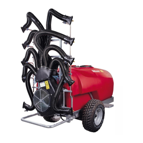
The schematic diagram opposite shows the fluid
flow of the TGS Grape Sprayer.
The main tank can be filled either through the top or
the bottom but the recommended method is through
the bottom fill connection, which is more convenient
and prevents chemicals from frothing. The bottom
fill incorporates a cam-lock hose coupling.
If the top lid is used for filling, a basket strainer is
provided to prevent entry of foreign material.
The level of liquid in the main tank is shown by a
floating ball sight-line and calibration marks on the
LH side of the sprayer.
For rapid emptying, a large diameter outlet under
the LH side of the sprayer discharges through a
manual drain valve. During filling and spraying this
valve is turned to the “Pump” position. Turning the
valve to its midpoint (handle vertical) closes the
valve to allow removal of the suction filter element
without losing fluid from the tank
Liquid chemicals are added to the main tank with a
detachable inductor probe and hose, connected by
a cam-lock coupling to a venturi in the tank. Opening
the inductor valve, mounted on the pump, directs
pressurised fluid from the pump to the venturi and
applies suction to the probe. Solid chemical can be
dissolved in water to allow use of the probe or it can
be added through the top opening in the tank.
The chemical mixture is drawn from the underside
of the tank through the suction line to the inlet side
of the diaphragm pump, which is driven directly by
the PTO shaft. A filter in the suction line ensures
that no foreign material enters the pump. The filter
incorporates a replaceable element.
Fluid is discharged from the pump through a manual
pressure regulator to a 12 volt electrically operated
valve block, mounted at the front of the sprayer.
The manual pressure regulator is used to set the
spraying pressure, which is shown on the pressure
gauge mounted at the pump.
The electric valve block incorporates a Master on/off
valve and two boom Section on/off valves that are
operated by switches on a control box mounted in
the cabin. The Master on/off switch changes the
pump between by-pass and pressure modes. The
Section on/off switches stop and start spraying on
the left and right sides of the boom.
By-passed fluid from the pressure regulator and
Master valve is returned to the underside of the
main tank, which keeps the chemical solution
mixed.
Two propeller agitators in the front of the tank are
belt driven from the PTO shaft to provide further
mixing of the solution.
Boom Circuit
The boom section valves direct fluid to the spray
lines on the boom air tubes. The circuit diagram
shows the section of the boom that is controlled by
each valve. Once the boom pattern is set with the
section on/off switches, spraying is stopped and
started with the master switch.
Each spray line is connected to ten nozzles,
arranged in pairs on the five air diffusers of each air
tube. The application rate can be varied by fitting
nozzles with different size orifices.
An on/off tap on each pair of nozzles enables the
spray pattern to be varied. The taps incorporate a
non-drip valve that is activated once spraying
pressure falls below approximately 0.5 Bar. A tap at
the lower end of each spray line is used to flush the
system.
The turbine fan is driven at constant speed by the
PTO shaft through a direct coupled, two speed gear
box. Air is directed to the vertical air tubes of the
boom and discharged through the diffusers, which
atomizes the liquid discharged from the spray
nozzles. The angle of the diffusers can be adjusted
to vary the discharge pattern.
Clean Water Tank
The clean water tank is not connected to the
spraying circuit. It is filled through the top opening
and provides clean water for washing purposes
through a tap on either side of the sprayer. Under
no circumstances should it be used for drinking.


