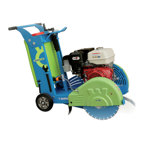
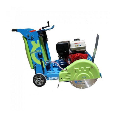
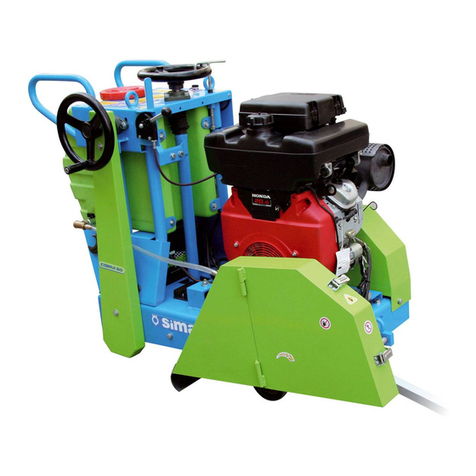
Sima COBRA-60 User manual

COBRA-60
E-1
RAMIRENT

2
ENGLISH
RAMIRENT

3
ENGLISH
INDEX
E-1................................................................................................................. 1
1. GENERAL INFORMATION............................................................................ 4
2. DESCRIPTION OF THE MACHINES .............................................................. 4
2.1 PICTOGRAMS...................................................................................................................5
3. TRANSPORT ............................................................................................... 5
4. ASSEMBLING INSTRUCTIONS .................................................................... 5
4.1 DELIVERY CONDITIONS....................................................................................................5
4.2 ASSEMBLING THE ELEVATION WHEEL ................................................................................6
4.3 PLACING THE BLADE ........................................................................................................6
5. EQUITMENT SAFETY RECOMMENDATION ................................................... 6
5.1 STARTING THE MACHINE ..................................................................................................6
5.2 MANAGEMENT OF THE MACHINE........................................................................................7
6. SAFETY RECOMMENDATIONS & PREVENTION MEASURES .......................... 7
6.1 MIND YOUR STEP.............................................................................................................7
6.2 COLISSIONS AND CONTACTS AGAINST MOVING PARTS, MOTIONLESS, OBJECTS AND / OR
TOOLS..................................................................................................................................7
6.3 PROJECTION OF FRAGMENTS OR PARTICLES.......................................................................8
6.4 ENTRAPMENT BY OR BETWEEN OBJECTS.............................................................................8
6.5 THERMAL CONTACT..........................................................................................................8
6.6 DANGEROUS SUBSTANCES:INHALATION, INGESTION AND CONTACT.....................................8
6.7 EXPLOSION AND FIRE.......................................................................................................8
6.8 SHOCK AND DEATH OF BODILY INJURY STRIKES OBJECTS. ..................................................8
6.9 NOISE AND VIBRATION. ...................................................................................................9
7. STARTING AND USE INSTRUCTIONS.......................................................... 9
7.1 WATER TANK...................................................................................................................9
7.2 ADJUSTING THE CUTTING BLADE HEIGHT...........................................................................9
7.3 DIESEL AND PETROL ENGINES ..........................................................................................9
7.4 ENGINE SAFETY RECOMMENDATIONS.................................................................................9
7.5 STARTING AND STOPPING USING MOTOR 13HP (COBRA-60/G13H) .....................................10
7.6 STARTING AND STOPPING USING MOTOR 20HP (COBRA-60/G20H) .....................................10
7.7 STARTING AND STOPPING USING DIESEL ENGINE (COBRA-60/G16R)..................................10
8. CUTTING MATERIALS............................................................................... 11
9. SAFETY RECOMMENDATIONS................................................................... 11
9.1 REPLACING THE BELTS................................................................................................... 12
9.2 REPLACEMENT DISC.......................................................................................................12
10. SOLUTIONS TO MOST FREQUENT ANOMALIES ....................................... 13
11. TECHNICAL CHARACTERISTICS.............................................................. 14
12. ELECTRIAL SCHEMES.............................................................................. 15
13. WARRANTY ............................................................................................ 17
14. SPARE PARTS......................................................................................... 17
15. ENVIRONMENT PROTECTION ................................................................. 17
16. NOISE LEVEL DECLARATIONS ................................................................ 17
17. VIBRATIONS LEVEL DECLARATIONS ...................................................... 17
WARRANTY CERTIFICATE ............................................................................ 21

RAMIRENT

4
ENGLISH
1. GENERAL INFORMATION
ATTENTION: Please read and understand perfectly the present instruction before using the machine.
SIMA S.A. thanks you for purchasing the FLOOR SAW model COBRA-60
This manual provides you with the necessary instructions to start, use, maintain and repair the floor saw. All
aspects as far as the safety and health of the users is concerned have been stated. Respecting all instructions and
recommendations assures safety and low maintenance. As such, reading this manual carefully is compulsory for any
person responsible for the use, maintenance or repair of this machine.
As such, reading this manual carefully is compulsory for any person responsible for the use, maintenance or
repair of this machine.
It is recommended to have always this manual in an easily accessible place where the machine is
being used.
2. DESCRIPTION OF THE MACHINES
The floor saws SIMA S.A., model COBRA 60, are designed and manufactured to cut onto flat surfaces
asphalt, concrete, terrazzo, granite or ceramics. High-speed diamond blades are used and advancement is manual.
The joint cutter COBRA 60 model 60 provides a side-wheel transmission to the drive wheels for easy push of the
machine and making the cut more easily and with less effort.
•Water tank with the possibility to connect the machine to the main water inlet.
Any misuse given to the floor saw will be considered as inappropriate and hazardous and remains
forbidden
•Its constructive characteristics are: adjusting the cutting height using a handle or a wheel that can be blocked
with an element to impede any undesirable movement.
•Emergency stop button situated in the control board.
•Flexible rubber tires and aluminium rims with double pillow block bearings.
•Blade protection included and blade water cooling with water tape to control the water flow.
•The machine is run by a combustion motor to generate the movement of the cutting blade.
•The accelerator of the motor is remotely controlled.
•The progress of the machine can be made by pushing on the machine, or through a wheel that transmits
movement to the machine with chain drive and gears, this transmission is protected by a comprehensive
backup prevents access to the moving parts.
•The frame is coated with a highly resistance anti-corrosion epoxy, polyester paint
•The machine is furnished with an anti-splatter screen in the cutting blade safeguard to avoid water splashes
towards the backward cutting area of the machine.
•Guiding pointer to as check the straightness of the cutting
•The machine has transmission pulleys and a flexible belt. The transmission is protected by a safeguard to
avoid any Access to the moving elements
•The chassis has elements of elevation to facilitate the transport of the machine.
•In height-adjustable handlebars offering comfort and ease of conduction to the operator.
RAMIRENT

5
ENGLISH
•A graduated scale indicating the cutting depth.
2.1 PICTOGRAMS
Pictograms included in the machine entail the following:
3. TRANSPORT
For short distances, the floor saw COBRA 50 can be transported onto its own wheels. Raise the blade fully and
move the saw manually.
When the machine must be lifted, use the hook located on the front part. It will be then easy to fix steel
cables or chains C, Fig. 2. The transport to be used should ensure the machine safety.
WARNING: use highly- resistant cables or chains (bear in mind the weight of the machine and see the
metal label of the machine).When you put down the machine, do it gently and avoid any strong bumps on
the wheels that could damage other components.
4. ASSEMBLING INSTRUCTIONS
4.1 DELIVERY CONDITIONS
The different versions of floor saws COBRA 60 models are supplied and single-packed suitable for safe
transport.
When removing the package, you should find the machine with no disk, no fuel and a bag with the following
items:
•Two handles for advance wheel control and elevation of the disc.
•6 mm key allen.
•A manual of the machine and its warranty.
•Instruction engine book.
READ
INSTRUCTIONS
MANUAL
USE SAFETY GLOVES
USE HELMET AND EYE AND EAR
DEFENDERS
USE SAFETY FOOTWEAR
RAMIRENT

6
ENGLISH
4.2 ASSEMBLING THE ELEVATION WHEEL
The height adjusting wheel, C, Fig.3 is mounted in factory without its handle A, Fig.3 for packing reasons
and to avoid possible shocks during transport. To assemble this handle, you need to place it on the wheel, fastening it
with a 6 mm Allen key D, Fig.3. The handle screwed spot is the housing for the Allen key.
4.3 PLACING THE BLADE
A good choice ensures a good performance and agood final result.
Blades must be cooled. Accordingly the floor saw COBRA 60 has a water spray system that ensures a steady
stream of water.
The blade safeguard of COBRA 60 can be lifted from one of its ends: assembly and blade replacement are
then quick and easy.
To place or replace the blade, you must proceed as follows:
•In machines with a steel safeguard, loosen the protection locks P, Fig.4 and open the foldable part of protection.
For installation or replacement of the disc, proceed as follows:
•Loosen the screws C, Fig.4 holding the safeguard to the chassis.
•Block the rotation of the blade shaft with a flat spanner L, Fig.7 supplied with the machine. The blade shaft has two
flat faces to allow placing the spanner without any trouble.
•Loosen the screw of the blade shaft T, Fig.4 with a flat spanner M, Fig.4 and remove the outer flange E, Fig.4.
WARNING: the nut is left-threaded.
•Place the blade on the shaft and coincide the small hole with the dowel pin of the inner flange plate. (I, Fig.4).
•Place the outer flange plate making sure the dowel pin passes through the blade into the rear flange plate.
•Tighten firmly the safeguard using the two flat spanners provided.
•Make sure that the rotation of the blade is always correct. It must coincide with the arrow marked on the
blade as well as with the one marked on the blade safeguard.
5. EQUITMENT SAFETY RECOMMENDATION
WARNING: Before starting the machine, read the instructions carefully and observe safety rules
recommended in this manual and labor safety standards of each location to avoid accidents, damage and
injury:
The SIMA Joint Cutters should be used by people who are familiar with its operation.
• Make sure the machine will be use in perfect technical condition and fully operational.
• Do not operate the machine unless all guards have mounted that has been designed.
• When moving the machine do with the engine stopped.
• Before starting the machine, make sure that the blade does not touch the ground.
• Do not use pressurized water to clean the engine.
• Do not use the machine to different functions that it has been designed.
• Do not use the machine in the rain, cover it with waterproof material.
5.1 STARTING THE MACHINE
• Always use personal protective equipment (EPI) appropriate for each job.
• Visually inspection the machine (levels, wear, shooting, etc.) before starting.
• Do not operate the machine, or operate the controls if operator is not located in the operator location.
• Examine the control panel and verify that all devices are working properly measuring and monitoring safety.
RAMIRENT

7
ENGLISH
• Before connecting or starting the equipment make sure that nobody is in their area of risk.
• Starting the equipment according to the manufacturer's instructions.
• Check the rotation direction is correct.
• Visually inspect all connections: bolts, nuts, welds, corrosion, cracks, receipts, etc.
5.2 MANAGEMENT OF THE MACHINE
•Stop the equipment according to manufacturer's instructions.
•Keep clean the equipment.
•Check the condition of the equipment, holder tools, tools, accessories and whether they are
adequate.
This equipment will be used only by authorized and trained personnel with specific training and
appropriate.
If the equipment is not working properly please report immediately to his superior.
6. SAFETY RECOMMENDATIONS & PREVENTION MEASURES
• Do not operate the machine if anomalies that may affect the safety of persons.
• Keep safety signs clean installed on the machine and replace any that are missing.
• The maintenance, servicing and general repairs will be made only by authorized personnel.
• Observe all signs point to the work.
• Do not manipulate the safety devices under any circumstances.
• Ensure proper lighting for night work or in low light areas.
• Maintenance of the machine can be dangerous if not done according to manufacturer's specifications.
• Wear work clothes tight. Do not wear rings, bracelets, chains, etc.
• Cleaning and maintenance will be with the machine stopped with no possibility of movement or operation.
6.1 MIND YOUR STEP
• Keep work area clean of materials, tools, utensils, etc.
• Be careful to avoid twisting movements and wear appropriate footwear.
6.2 COLISSIONS AND CONTACTS AGAINST MOVING PARTS, MOTIONLESS, OBJECTS AND /
OR TOOLS
• Pay attention to anything that is moving in your work area.
• Pay special attention to their own movements.
• Be especially careful when traveling in work zones due to the narrowness and outgoing items.
• Store this equipment not used in the places allocated for this purpose.
RAMIRENT

8
ENGLISH
• Use the tools in good condition and only for jobs that were designed (do not keep in your pockets).
• Do not store sharp tools with cutting edges uncovered.
• Cleaning and maintenance will be done with the machine stopped with no possibility of movement or operation.
• Make sure all grills, casings and protections of the moving parts are properly installed.
6.3 PROJECTION OF FRAGMENTS OR PARTICLES.
• Make sure nobody is in the range of the equipment or operating area of its working.
• Check the condition of the equipment, holder tools, tools, accessories and whether they are adequate.
• Do not remove protective shields and other protective components installed.
6.4 ENTRAPMENT BY OR BETWEEN OBJECTS.
• Cleaning and maintenance will be with the team standing and unable to move.
• Make sure nobody is in the range of the equipment or operating area of its working.
• Grids and security guards that prevent contact with moving parts must be kept properly adjusted.
6.5 THERMAL CONTACT.
• Wear protective gloves during the replacement or supplying lubricating oil.
• Avoid contact with hot parts of the machine.
• Avoid exposure to gas emissions of your machine as It may cause burns.
6.6 DANGEROUS SUBSTANCES:INHALATION, INGESTION AND CONTACT
• Do not be operating the machine without guarantee proper ventilation and drag of the exhaust.
• In dusty environment you must use protective mask.
• Pay attention when handling hazardous substances (cement, resins, additives, fluids etc.).
6.7 EXPLOSION AND FIRE.
• Refuel with the engine stopped, ventilate places, extreme caution when filling and avoid spills.
• Do not smoke/not use mobile phones during the refueling operation.
• Do not ever check the battery level, fuel, etc..while smoking or lighting the way with lighter or matches.
• Check for fuel leak and never perform this operation using matches or lighters
• Do not weld or apply heat near the fuel system, oil or other flammable materials.
6.8 SHOCK AND DEATH OF BODILY INJURY STRIKES OBJECTS.
• Make sure nobody is in the range of the equipment or operating area of its working.
• For aslope work we will operate the machine downstream.
RAMIRENT

9
ENGLISH
6.9 NOISE AND VIBRATION.
• Use protective items if the job require them.
NOTE: Must follow all safety recommendations showed in this manual and comply with regulations
for the prevention of occupational risks in each place.
Be environmentally friendly. SIMA SA is not responsible for any consequences that may result in misuses
when cutting with Cobra 60 models.
7. STARTING AND USE INSTRUCTIONS
7.1 WATER TANK
COBRA 60 models , incorporate a water tank for cooling the disc. It has provided a stopcock flow on the right
side of the tank which allows us to open and close the water supply L, Fig.7
7.2 ADJUSTING THE CUTTING BLADE HEIGHT
COBRA 60 models are equipped with a height regulation system which is situated on the depth crank located
on the front part of the machine V, Fig.5. To lower the blade onto the cut, turn the control lever clockwise. To raise
the blade, turn it counter-clockwise as per the symbols shown on the machine Fig. 5
The position of the blade is shown on the cutting depth indicator I,Fig. 5 incorporated in these models.
To avoid vibrations due to unforeseen rotations of the control lever, the machine is equipped with a simple mechanism
which blockades the control lever onto the desired position B, Fig.5.Release the lever each time the height is being
modified.
7.3 DIESEL AND PETROL ENGINES
The COBRA 60 models are manufactured in several versions with diesel or gasoline engines, see technical
specifications.
All versions are supplied with engine oil and without fuel and includes an instruction book prepared by the engine
manufacturer.
WARNING: We must observe at all times the engine specific instructions included in its own manual.
For the supply of fuel, use a funnel or similar useful to avoid spillage on the machine and they can be
dangerous or involve some element of it.
7.4 ENGINE SAFETY RECOMMENDATIONS
• Fill the fuel tank and do not overfill in ventilated places.
• Try to avoid inhalation of the vapor rising from the refill.
• Avoid spilling fuel and keep in mind this operation every time you fill the tank, the fumes and spilled fuel is
highly flammable under certain conditions and may ignite.
• Do not smoke during the filling operation and avoid the presence of fire or sparks even in the fuel store.
• If fuel is spilled must be cleaned and allow dissipation of the fumes before starting the engine.
• Never place flammable items on the engine.
• Avoid contact with skin fuel.
• Do not allow the engine to be used without having in mind the necessary instructions.
• Do not touch the engine or allow anyone else to do it when still hot as it can cause skin burns.
• Never allow children or pets to be close to the engine.
• Keep the fuel out of the reach of children.
RAMIRENT

10
ENGLISH
• Do not refuel with the engine running or smoke during operation, try to do it in well ventilated places.
For further details, consult the engine manual.
7.5 STARTING AND STOPPING USING MOTOR 13HP (COBRA-60/G13H)
Proceed as follows:
•Raise the blade some centimetres from the ground.
•Check the engine oil level. If too low, the engine will not start.
•Open the fuel valve in the engine.
• Close the throttle. (Not necessary to keep it open if the engine is hot or the temperature is high).
• Place the throttle control G, Fig.5 acceleration position.
• Turn on the engine switch.
• unlock the stop button E, Fig.5 turning and moving it up. This switch is in addition to the switch engine and
allows more convenient functions STOP / START.
• Start the engine pulling the recoil starter handle.
• Let the engine warm up at low revolutions and then open the throttle and the throttle control to put in the
position of acceleration for the job intended.
• To stop the engine, raise the disc above the ground, decelerating completely and lock the push button E,
Fig.5 pushing it down. This switch is an emergency stop type. It is not necessary turn the switch in position
OFF to make stop the machine.
• Close the fuel valve in the engine.
For details on operations in the engine, see your instruction book.
7.6 STARTING AND STOPPING USING MOTOR 20HP (COBRA-60/G20H)
The 20HP engine models come with electric start and proceed as follows:
•Raise the blade some centimetres from the ground.
•Check the engine oil level. If too low, the engine will not start.
•Open the fuel valve in the engine.
• Close the throttle. (Not necessary to keep it open if the engine is hot or the temperature is high).
• Place the throttle control G, Fig.5 acceleration position.
•Start the engine by turning the ignition key to START position (right position). Keep this position a few
seconds. If after 5 seconds the engine has not started, release the key to reach ON position
(intermediate position) and wait 10 seconds before try again.
Once started the engine, drop the key into position where it will remain ON while in motion.
• Let the engine warm up at low revolutions and then open the throttle and the throttle control to put in the
position of acceleration for the job intended.
• To stop the engine, raise the disc above the ground, decelerating completely.
• Close the fuel valve in the engine (therefore the fuel flow will be close to the carburator).
For details on operations in the engine, see your instruction book.
7.7 STARTING AND STOPPING USING DIESEL ENGINE (COBRA-60/G16R)
The diesel models are supplied with electric start 16 HP and proceed as follows:
• Raise the blade until a few centimeters above the ground.
• Place the throttle G, Fig.6 towards halfway.
RAMIRENT

11
ENGLISH
• Place the ignition key in A position (left position) and start the engine by turning it to position C (right position).
Once the engine started place the key in position B (intermediate position). Do not keep the key in position A or
disconnect the battery with the engine running.
• Place the throttle lever to minimum and let the engine warm up for several minutes, then you need to accelerate
enough to do the job.
• To stop the engine, raise the disc above the ground, desacelerate completely, and pull the lever stop M, Fig.6
• Turn the ignition key into position A.
8. CUTTING MATERIALS
Cobra 60 joint cutter carries out duties safely and easily by following these recommendations:
Start the engine with the disk outside the cutting area.
Place the machine with the disk on the planned line of work and cutting down the guide G, Fig.7 to coincide
with the reference line.
Before starting to cut, open the water tank tap (L, Fig.7). whenever possible to connect directly to the
cooling water distribution network, Cobra 60 model incorporates a "T" connection provided for this purpose and
located adjacent to the stopcock.
If the cooling of the disc is going to be done from the deposit, the "T" connection is closed with a screw cap
and the stopcock L, Fig.7 is open to make way for water cooling if you want from the network will remove the screw
cap and connect the hose to be used, in this case the stopcock should be closed.
The disk must receive sufficient water to ensure perfect cooling. A bad disk cooled suffer damage and
premature wear.
With the engine at maximum revolutions, we down the disk slowly to achieve the desired cutting depth. While the
blade is descending, it should give a slight advance on the machine to avoid duplication of work arc of the disc itself.
Having gained the required cutting depth, turn the wheel of progress A, Fig.7 forward to move the machine
in the direction of the predetermined cutting line. Speed cutting shall not exceed that which allows the disk as a
function of the depth of cut, material hardness and engine power. If the disk tends to get out of the cut is due to
excessive advance and we will therefore decrease it.
Do not try to correct the cut line pulling hard the machine because it may cause deformations in the disc and
damage to other elements.
To stop the machine, proceed prior to removing the disc from the cutting area, lifting a few centimeters from
soil, as indicated in this manual. Never stop on the machine with the disc inside the cutting done.
9. SAFETY RECOMMENDATIONS
Maintenance operations should be carried out preferably by persons who know the machine and its operation.
• Any manipulation of the machine should be done with the engine stopped.
• Always consider the safety recommendations mentioned in this manual as well as the recommendations in the
engine manual
• Grease every 80 hours the following, bearing supports A, Fig.9 for the disk's axis, bearing supports frame B,
Fig.9 bearing supports for the rear wheels C, Fig.9, bearing support lifting A, Fig.10, spindle lift and feed chain
• On models with electric start properly maintained battery terminals protected against corrosion products for this.
• The engine maintenance is defined as manual, both in the operations required, as in the time periods to be
performed.
• Clean the machine as often as necessary and see if anomalies or malfunctions it inspected by a qualified technician.
• Be sure to remove the machine tools and devices used in each maintenance operation.
• If the machine is not covered, cover it with waterproof material.
• It is prohibited any change in any of the parts or elements of the machine by the user.
RAMIRENT

12
ENGLISH
9.1 REPLACING THE BELTS.
C Fig.8 transmission belts, are elements that with time of use enough loosen the tension below the limit. It is
necessary to periodically check your tension is correct so that pressing it hard with the fingers, the deformation is
achieved should be approximately 8 mm.
Also can be worn with the normal work of the machine so it will require replacement when damaged.
To check the belt tension, tighten or replace them, we will remove the protection P, Fig.8 loosen the screws T, Fig.8.
To tense the belts, we must move the motor toward the water tank, for which, first and foremost, to loosen the bolts
that attach it to its platform A, Fig.8, then loosen the rear tensor enough as to move the motor toward the water
tank, then pulled the tensor S, Fig.8. Once we get the proper tension, put the nuts back as well as the tensors.
If what you have to do is change belts, we have to move the engine in the opposite direction to the water tank, for
thereby loosen the bolts that attach it to its platform A, Fig.8 and the tensor S , Fig.8. thus it totally slack and can
be easily replaced.
Then he will move the engine to the tank by pressing the tensor S, Fig.8 to get the correct tension of the belts. Finally
pressed again the engine nuts and tensors.
Whenever you remove the protection P Fig.8 for an operation in the drive belts, it should also verify the correct
alignment between the motor and pulley drive. This operation is done by supporting a rule on the outside of them and
checking that there is no separation at any point.
If they were not aligned, the engine will move to where it is necessary to achieve proper alignment, making sure the
straps are also well stretched.
After any of these operations we will place the protection again back P, Fig.8 and to fix it with screws T, Fig.8.
WARNING:Transmission belts need to be revised and stretched after a working day of 8 hours, this
demonstrated that after several hours of work, transmissions of classical profile belt length increase due
to friction, temperature, voltages, etc. ..
When the transmission of the machine is flat belts toothed profile is not necessary to adjust the tension,
this transmission does not require excessive tension except that necessary for its proper functioning.
9.2 REPLACEMENT DISC.
A blade in good condition is essential for optimal performance of the joint cutters. Replace them when it is worn or is
cracked or crooked, following the instructions in this manual.
Do not use any other type of media other than specified in the manual and see which has the characteristics required
of maximum diameter, diameter of central hole and supported maximum number of revolutions.
Note that within the group of diamond disks are different types depending on the material being cut. Always choose
the most appropriate for you.
For all the above, we recommend using SIMA ORIGINAL BLADES always fulfilling the technical and safety requirements
and are offered in a range that covers all needs and facilitates the correct choice.
RAMIRENT

13
ENGLISH
10. SOLUTIONS TO MOST FREQUENT ANOMALIES
ANOMALIA
POSIBLE CAUSA
SOLUCION
The engine will not start
Low oil level alarm is ON
Top up as necessary
Fuel cock closed
Open fuel cock
Motor switch is in OFF position
Turn switch to ON position
Machine emergency stop switch is
pressed Release the button turning it upwards
Blade stops turning and will not cut as
it should be
Insufficient acceleration
Accelerate a bit the motor
belts loosened
Tighten the belts
Excessive advance
Decrease the advance
Inadequate blade
Use the adequate blade for the
material to be cut.
Low tension of the motor Let a technician check the motor
Premature wearing-out of the blade
Insufficient cooling
Make sure sufficient water arrives to
the blade
Excessive advance
Decrease the advance
Inadequate blade
Use the adequate blade for the
material to be cut.
Premature wearing-out of the
transmission belts Belts are slipping over the pulleys
Tighten the belts
Decrease the advance
Use the adequate blade for the
material to be cut.
Pulleys incorrectly tightened Align pulleys
RAMIRENT

14
ENGLISH
11. TECHNICAL CHARACTERISTICS
DATOS COBRA 60 G13H COBRA 60 G20H COBRA 60 D16R
MOTOR HONDA GX390 HONDA GX620 RUGGERINI MD190
COMBUSTIBLE PETROL PETROL DIESEL
START Manual
Electrical
Electrical
MAXIMAL POWER 13HP/9,6KW
20HP/14,9KW
15,5HP/11,4KW
R.P.M. MOTOR 3600
3600
3600
ADVANCE OF THE CUTTING Manual/Wheel
Manual/Wheel
Manual/Wheel
Ø OUTER DISCO mm. 600
600
600
Ø INNER DISCO mm. 25,4
25,4
25,4
BLADE SITUATION Right
Right
Right
CUTTING DEPTH mm. 200 mm
200 mm
200 mm
CAPACITY OF THE WATER TANK L. 50
50
50
COOLING OF THE BLADE Tow faces Tow faces Tow faces
NET WEIGHT Kg. 188 234 245
DIMENSIONS
L x A x H mm. 1410x700x990
1410x700x990
1410x700x990
RAMIRENT

15
ENGLISH
12. ELECTRIAL SCHEMES
ESQUEMA ELECTRICO COBRA-60-D16R
ESQUEMA ELECTRICO COBRA-60-G20H
RAMIRENT

16
ENGLISH
ESQUEMA ELECTRICO COBRA-60-G13H
RAMIRENT

17
ENGLISH
13. WARRANTY
SIMA, S.A. the manufacturer of light machinery for construction possesses a net of technical services “SERVI-
SIMA”.
Repairs under warranty made by SERVÍ-SIMA are subject to some strict condition to guaranty a high quality
and service.
SIMA S. A. guarantees all its products against any manufacturing defect; to take into account the conditions stated in
the attached document “WARRANTY CONDITIONS”. The latter would cease in case of failure to comply with the
established payment terms. SIMA S.A. reserves its right to bring modifications and changes to its products without
prior notice.
14. SPARE PARTS
The spare parts for the floor saws COBRA-60-G13H, COBRA-60-G20H y COBRA-60-D16R, manufactured by SIMA,
S.A. are to be found in the spare parts plan, attached to this manual.
To order any spare part, please contact our alter-sales service clearly indicating the serial number of the machine,
model, manufacturing number and year of manufacturing that show on the characteristics plate.
15. ENVIRONMENT PROTECTION
Raw materials have to be collected instead of throwing away residuals. Instruments, accessories,
fluids and packages have to be sent into specific places for ecological reutilisation. Plastic components are
marked for selective recycling.
R.A.E.E. Residuals resulting from electrical and electronic instruments have to be stored into
specific places for selective collection.
16. NOISE LEVEL DECLARATIONS
Level of acoustic power issued by the machine:
COBRA-60/G13H
COBRA-60/G20H
COBRA-60/D16R
109,8 dB
113,1 dB
110 dB
The figures showed below are only emissions levels, not necessarily levels that can work safely. Although there is a
correlation between emission levels and exposure they can not reliably be used to determine if preventive measures
are necessary supplements. The parameters that influence the actual level of exposure, include the duration of
exposure, site characteristics, other sources of noise, etc.
Moreover, permissible exposure levels may vary from one country to another. However, this information allows the
user of the machine to a better risk assessment.
17. VIBRATIONS LEVEL DECLARATIONS
The level of vibrations transmitted to the hand-arm:
MODEL LEFT HAND m/ s² RIGHT HAND m/ s²
COBRA-60/G13H
0,14072443422
0,08137014619
COBRA-60/G20H 0,05672 0,04528
COBRA-60/D16R
0,04906034208
0,01526361615
RAMIRENT

18
ENGLISH
RAMIRENT

19
ENGLISH
RAMIRENT

20
ENGLISH
RAMIRENT
Other manuals for COBRA-60
1
Table of contents
Other Sima Saw manuals

Sima
Sima DAKAR User manual

Sima
Sima COBRA-60 User manual

Sima
Sima EUROTRON PLUS User manual

Sima
Sima AMBAR 200 User manual

Sima
Sima MAGNUM 700 User manual

Sima
Sima HANDY 350 User manual

Sima
Sima COBRA-40 User manual

Sima
Sima AMBAR 200 User manual

Sima
Sima TRENCHER 60/70 FE G13H User manual

Sima
Sima MAGNUM 700L User manual
Popular Saw manuals by other brands

MasterCraft
MasterCraft 054-8255-8 instruction manual

Jet
Jet VSF-14-1 Operating instructions and parts manual

Hoteche
Hoteche P805201A manual

Parkside
Parkside PZKS 2000 B2 Operating and safety instructions

EINHELL
EINHELL TH-TS 1725 U Original operating instructions

Hitachi
Hitachi CB 13F Instruction manual and safety instructions