4
ENGLISH
1. GENERAL INFORMATION
WARNING: P as r ad and und rstand p rf ctly th pr s nt instruction b for using th machin .
SIMA S.A. th nks you for your trust in our products nd for purch sing the TABLE SAW model BALI.
This m nu l provides you with the necess ry instructions to st rt, use, m int in nd in your c se, rep ir of
the present m chine. All spects s f r s the s fety nd he lth of the users is concerned h ve been st ted.
Respecting ll instructions nd recommend tions ssures s fety nd low m inten nce. As such, re ding this m nu l
c refully is compulsory for ny person responsible for the use, m inten nce or rep ir of this m chine.
As such, re ding this m nu l c refully is compulsory for ny person responsible for the use, m inten nce or
rep ir of this m chine.
It is r comm nd d to hav always this manual in an asily acc ssibl plac wh r th machin is b ing
us d.
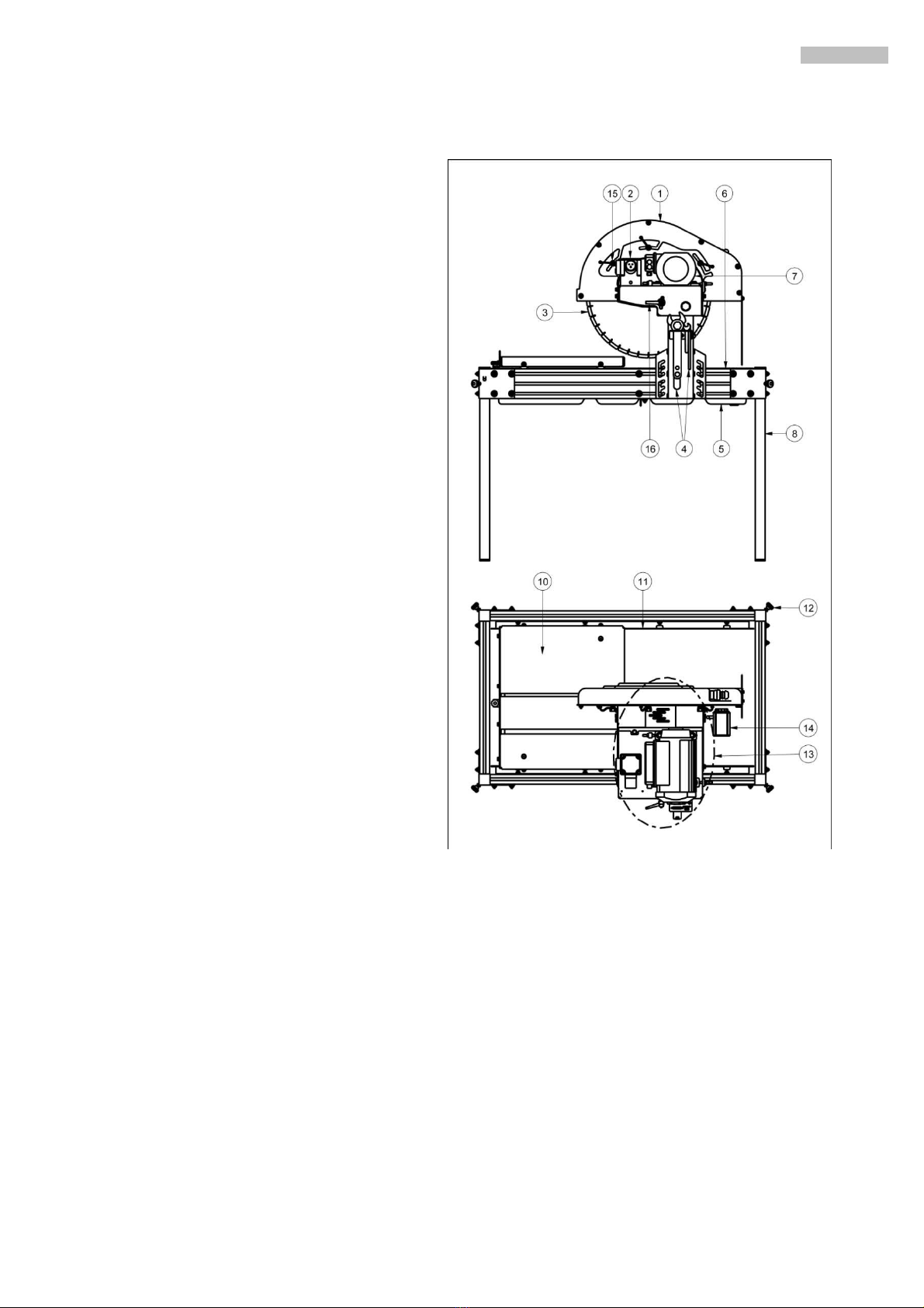
2. GENERAL DESCRIPTION OF THE MACHINE
SIMA Cutting T ble S ws, B li models, re designed nd m nuf ctured to be used t m sonry building sites,
in p rticul r to cut until 20 cm high concrete blocks nd other construction m teri ls, miner l nd compounds with t
le st one be ring side (tile, terr zzo, brick, m rble, gr nite, concrete or cer mics shingle, stonew re... The cutting tool
is di mond bl de powered by n electric motor nd w ter cooled by closed-circuit pump. The progress of the bl de
is done m nu lly by moving the cutting he d in the direction of the m teri l to be cut. The B li models re
m nuf ctured of high qu lity m teri ls.
Any us oth r than th machin has b n d sign d for is consid r d inappropriat and can b
dang rous; th r for , it is xpr ssly prohibit d.
•B li models re designed to solve the problem of cutting m teri ls 20 cm high with the ppropri te di mond
bl de.
•En ble to move the he d up nd down directions e sily nd m nu lly w y, through turning nd blocking the
he d using the h ndle proportion te for the purpose
•The he d of the motor keep the right b l nce even when the block is c ncel due spring.
•Its steel ch ssis void vibr tions during cutting. Therefore we get better efficiency of the di mond bl de.
•The c rry in sliding c rt is build with V wheels tre d design.
•A rubber protection is dispose on the sliding c rt in its upper side to void the sliding of the m teri l being
cut.
•The m chine h s four demount ble legs to f cilit te its tr nsport nd h ndles for its displ cement.
•The m chine is protected with n nti-spl tter screen to void the w ter spl shing tow rds the b ck p rt of
the m chine where the cutting is being performed.
•B li models h ve det ch ble legs to f cilit te their tr nsport.
•The ction of the di mond bl de is m de through belts, getting tot l silence.
•The fr me of the m chine is p inted with highly resist nt nti-corrosion epoxy polyester p int.
•This m chine h s been designed nd m nuf ctured to cut with w ter cooled di mond bl de. The cooling is
c rried out by closed-circuit electric pump with const nt w ter flow.
•The electric pump with high imped nce winding voids its burning in norm l conditions of use nd cert inly
th t it is lw ys covered with w ter.