manuals.online logo
Brands
  1. Home
  2. •
  3. Brands
  4. •
  5. Sime
  6. •
  7. Boiler
  8. •
  9. Sime MUREL LE HE ErP Series User manual

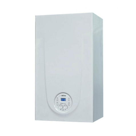
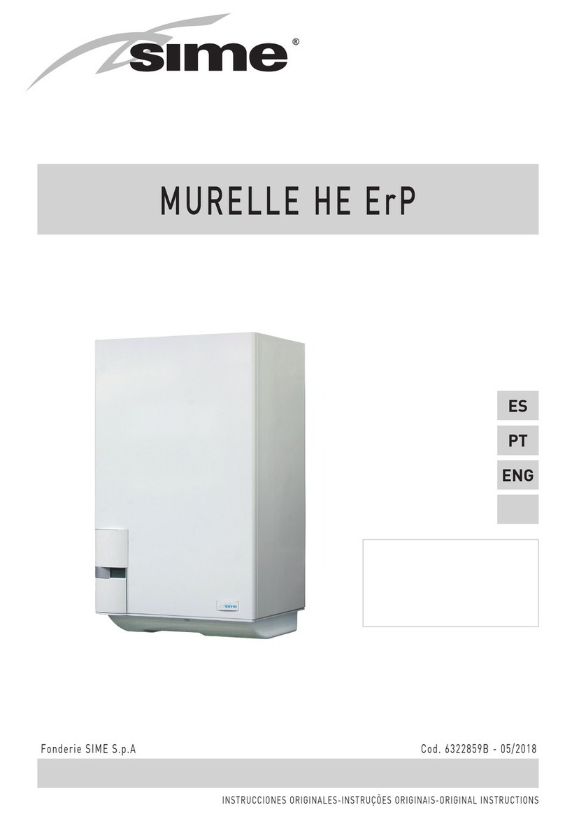
Sime MUREL LE HE ErP Series User manual

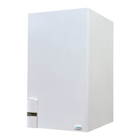
MURELLE HE 25-30/55 ErP
Fonderie SIME S.p.A C od. 6322875B - 03/2017
ENG
INSTALLER INSTRUCTIONS
CONTENTS
1  DESCRIPTION OF THE BOILER .......................................................................................................... pag. 68
2  INSTALLATION ................................................................................................................................... pag. 72
3  CHARACTERISTICS ............................................................................................................................ pag. 83
4  USE AND MAINTENANCE .................................................................................................................. pag. 90
IMPORTANT
When carrying out commissioning of the boiler, you are highly recommended to perform the following
checks:
–
Make sure that there are no liquids or inflammable materials in the immediate vicinity of the boiler.
– Make sure that the electrical connections have been made correctly and that the earth wire is con-
nected to a good earthing system.
– Open the gas tap and check the soundness of the connections, including that of the burner.
– Make sure that the boiler is set for operation for the type of gas supplied.
– Check that the flue pipe for the outlet of the products of the combustion is unobstructed and has been
properly installed.
– Make sure that any shutoff valves are open.
– Make sure that the system is charged with water and is thoroughly vented.
– Check that the circulating pump is not locked.
– Purge the system, bleeding off the air present in the gas pipe by operating the pressure relief valve
on the gas valve inlet.
–
The installer must provide the user with instruction in operation of the boiler and safety devices and
hand over the instruction booklet to the user.
MURELLE HE 25-30/55 ErP - ENGLISH
CONFORMITY
Our Company declares that MURELLE HE 25/55 - 30/55 ErP boilers comply with the essential require-
ments of the following directives:
- Boiler Efficiency Directive 92/42/EEC
- Gas Appliances Directive 2009/142/EC
- Electromagnetic Compatibility Directive 2014/30/UE
- Low Voltage Directive 2014/35/UE
- Ecodesign Directive 2009/125/EC
- Regulation (EU) N. 813/2013 - 811/2013
68
1.1   INTRODUCTION
MURELLE  HE  25-30/55  ErP  are premi-
xed gas condensation thermal modules
that employ a microprocessor-based
technology to control and manage all the
functions.
For optimum installation and operation,
always follow the instructions provided in
this manual.
1  DESCRIPTION OF THE BOILER
80
110
C
S3
15 6L460
==
10015 270 10078
470
600
ø 60/100
EUMR G
90
950
980
1065
425
E
U
M
R
G
Fig. 1
FIXTURES
R C.H. return G 3/4” (UNI - ISO 228/1)
M C.H. flow G 3/4” (UNI - ISO 228/1)
G Gas connection G 3/4” (UNI - ISO 228/1)
E D.H.W. inlet G 1/2” (UNI - ISO 228/1)
U D.H.W. outlet G 1/2” (UNI - ISO 228/1)
C Recirculation G 1/2” (UNI - ISO 228/1)
S3 Condensation outlet ø 25
1.2  DIMENSIONS (fig. 1)
  L (mm)
Murelle HE 25/55 ErP 286
Murelle HE 30/55 ErP 222
69
ES
PT
ENG
Model Murelle HE  25/55 ErP  30/55 ErP
Heat output
Nominal (80-60°C) (Pn max) kW 23.9 28.9
Nominal (50-30°C) (Pn max) kW 26.2 31.6
Reduced G20 (80-60°C) (Pn min) kW 6.1 7.6
Reduced G20 (50-30°C) (Pn min) kW 7.0 8.5
Reduced G31 (80-60°C) (Pn min) kW 7.5 8.7
Reduced G31 (50-30°C) (Pn min) kW 8.5 9.6
Heat input (*)
Nominal (Qn max - Qnw max) kW 24.5 29.5
Reduced G20/G31 (Qn min - Qnw min) kW 6.5/8.0 8.0/9.0
Min./Max. in useful yield (80-60°C) % 94/97.6 95/98
Min./Max. useful yield (50-30°C) % 107/107 107/107
Useful yield at 30% of the load (40-30°C) % 107,2 107,4
Losses after shutdown to 50°C (EN 15502)  W 94 95
Supply voltage V-Hz 230-50 230-50
Adsorbed power consumption (Qn max) W 90 94
Adsorbed power consumption (Qn min) W 58 59
Electrical protection grade IP X4D X4D
Energy efficiency
Seasonal energy efficiency class of the heating system A A
Seasonal energy efficiency of the heating system % 91 92
Sound power of the heating system dB (A) 49 50
D.H.W. energy efficiency class B B
D.H.W. energy efficiency % 76 77
D.H.W. load profile declared XL XL
C.H. setting range °C 20/80 20/80
Water content boiler l 9.6 10
Maximum water head (PMS) bar (kPa) 3 (294) 3 (294)
Maximum temperature (T max) °C 85 85
Capacity/Pressure of the heating expansion vessel l/bar (kPa) 10/1 (98) 10/1 (98)
D.H.W. setting range °C 10/65 10/65
D.H.W. flow rate (EN 13203) l/min 15.5 17.5
Continuous D.H.W. flow rate (∆t 30°C) l/min 11.3 13.8
D.H.W pressure min./max. (PMW) bar (kPa) 0.2/7.0 (19.6/686) 0.2/7.0 (19.6/686)
D.H.W. tank capacity l 55 55
Recuperation time between 25 and 55°C  min 6’ 30” 6’
D.H.W. expansion vessel capacity  l 2.5 2.5
Exhaust fumes temperature at max flow rate (80-60°C) °C 70 70
Exhaust fumes temperature at min. flow rate (80-60°C) °C 65 65
Exhaust fumes temperature at max. flow rate (50-30°C) °C 40 40
Exhaust fumes temperature at min. flow rate (50-30°C) °C 35 35
Smokes flow minimum g/s 3,34 3,89
Smokes flow maximum g/s 11,67 13,89
CO2 at max./min. flow rate (G20) % 9.0/9.0 9.0/9.0
CO2 at max./min. flow rate (G31) % 10.0/10.0 10.0/10.0
NOx measured 
(EN 15502-1:2015)
mg/kWh 36 42
PIN number 1312BU5312 1312BU5312
Category II2H3P II2H3P
Type B23P-B53P-C13-C33-C43-C53-C83 B23P-B53P-C13-C33-C43-C53-C83
NOx emission class 
(EN 15502-1:2015)
6 (‹ 56 mg/kWh) 6 (‹ 56 mg/kWh)
Weight when empty kg 68 70
Main burner nozzle
Quantity nozzles n° 1 1
G20 nozzle diameter ø 6.0/4.4 6.0/4.4
Gas consumption at maximum/minimum flow rate (G20) m3/h 2.59/0.53 3.12/0.66
Gas consumption at maximum/minimum flow rate (G31) kg/h 1.90/0.62 2.29/0.62
Gas supply pressure (G20/G31) mbar (kPa) 20/37 (1.96/3.63) 20/37 (1.96/3.63)
(*) Heat input of the heating system measured using lower heating value (LHV)
1.3  TECHNICAL FEATURES
70
5
3
4
1678
14
16
17
19
23
9
12
11
13
10
15
25 26 27
20
21
28
29
24
MCUEGRS3
1.4  FUNCTIONAL DIAGRAM (fig. 2)
Fig. 2
KEY
1 Fan
3 Primary exchanger
4 Limit stat
5 Air relief valve
6 Safety thermostat 100°C
7 C.H. sensor (SM)
8 Flow switch
9 Expansion vessel
10 D.H.W. tank
11 D.H.W. safety valve 7 bar
12 Magnesium anode
13 D.H.W. sensor (SB)
14 Safety valve
15 Gas valve
16 Pump high efficiency
17 Motor-operated diverter valve
19 D.H.W. expansion vessel
20 Water pressure transducer
21 Automatic bypass
23 D.H.W. drain cock
24 Condensate drain tap
25 Gas cock (optional)
26 C.H. return cock (optional)
27 C.H. flow cock (optional)
28 D.H.W. cock
29 Fixing jig (optional)
CONNECTIONS
R C.H. return
M C.H. flow
G Gas connection
E D.H.W. inlet
U D.H.W. outlet
C Recirculation
S3 Condensation outlet
71
ES
PT
ENG
1
2
3
4
5
6
7
8
9
10
11
12
13
14
15
16
17
18
19
20
Fig. 3
1.5  MAIN COMPONENTS (fig. 3)
KEY
1 Control panel
2 Pump high efficiency
3 Gas valve
4 Flow switch
5 C.H. sensor (SM)
6 Condensate drain tap
7 Fan
8 Detection electrode
9 Ignition electrode
10 Primary exchanger
11 Exhaust fumes probe
12 Air relief valve
13 Limit stat
14 Ignition transformer
15 D.H.W. safety valve 7 bar
16 Expansion vessel
17 Safety thermostat 100°C
18 D.H.W. sensor (SB)
19 D.H.W. storage tank
20 D.H.W. expansion vessel
MODEL
SERIAL NUMBER
YEAR OF CONSTRUCTION
WATER CONTENT IN BOILER
HEAT INPUT MAX
HEAT OUTPUT MAX (80-60°C)
HEAT OUTPUT MAX (50-30°C)
MAX OPERATING PRESSURE
CONTENTS D.H.W.
HEAT INPUT MAX D.H.W.
MAX OPERATING PRESSURE D.H.W.
D.H.W. FLOW RATE
POWER SUPPLY
MAX POWER ABSORBED
COUNTRIES OF DESTINATION
CATEGORY
TYPE
CODE
DIRECTIVE OF REFERENCE
PIN NUMBER
HEAT INPUT MIN
HEAT OUTPUT MIN (80-60°C)
HEAT OUTPUT MIN (50-30°C)
MAX OPERATING PRESSURE
HEAT INPUT MIN D.H.W.
MAX OPERATING PRESSURE D.H.W.
ELECTRICAL PROTECTION GRADE
NOx CLASS
CODE GAS COUNCIL NUMBER (UK)
CERTIFICATION WRAS (UK)
TYPE OF GAS
GAS SUPPLY PRESSURE
CLASSIFICATIONS
Fig. 3/a
1.6  TECHNICAL DATA PLATE (fig. 3/a)
72
The boiler must be installed in a fixed loca-
tion and only by specialized and qualified
firms in compliance with all instructions
contained in this manual. Furthermore,
the installation must be in accordance with
current standards and regulations.
2.1  INSTALLATION
– Boilers can be installed in all domestic
environments without any whatsoever
limit in terms of location and comburent
air supply.
– These boilers can also be installed in
partially covered areas, as per EN 15502,
with a maximum ambient temperature
of 60°C and a minimum ambient tempe-
rature of -5°C. It is generally advisable
to install the boilers below weathered
roofs, on the balcony or in a protected
niche, to protect them from exposure to
weathering agents (rain, hail and snow).
All boilers provide a standard antifreeze
function.
2.1.1 Anti-freeze function
The boilers are equipped with anti-freeze
function which activates the pumps and
the burner when the temperature of the
water contained inside the appliance drops
to below 6°C. The anti-freeze function is
ensured, however, only if:
- the boiler is correctly connected to the
gas and electricity supply circuits;
- the boiler is constantly fed;
- the boiler ignition is not blocked;
- the essential components of the boiler
are all in working order.
In these conditions the boiler is protected
against frost down to an environmental
temperature of -5°C.
ATTENTION:  In  the  case  of  installation 
in  a  place  where  the  temperature  drops 
below  0°C,  the  connection  pipes  must  be 
protected. 
2.2  BOILER SUPPORT BRACKET
For the mounting of the support bracket of
the boiler, which is supplied, observe the
following instructions (fig. 4):
– Fix the bracket to the wall with appro-
priate dowels.
– Check with a spirit level that it is per-
fectly in horizontal plane.
– To fix the boiler with the lives put in evi-
dence in figure.
2.2.1 Complementary accessories
To simplify connections to the hydraulic and
gas supplies, it is also possible to use the
following accessories:
– Mounting plate, code 8081217
– Kit with bends, code 8075423
– Kit with faucets, code 8091833
– Antifreeze heaters kit -15°C, code
8089805
– Mixed area kit ZONA MIX, code 8092234.
For detailed information on the assembly
of fittings, see the instructions contained
in the box.
2.2.2  Flow regulator (fig. 5)
In entrance of the D.H.W. a regolator of
color capacity is installed brown for the
vers. “25/55  ErP” and blue for the vers.
“30/55 ErP”; the regolator is inserted in a
bag to equipment of the boiler.
2.3  CONNECTING UP SYSTEM
To protect the heat system from damaging
corrosion, incrustation or deposits, before
installation it is extremely important to
clean the system using suitable products
such as, for example, Sentinel  X300 (new 
systems), X400 and X800 (old systems) or 
Fernox Cleaner F3. Complete instructions
are provided with the products but, for fur-
ther information, you may directly contact
SENTINEL PERFORMANCE SOLUTIONS
LTD or FERNOX COOKSON ELECTRONICS.
For long-term protection agains corrosion
and deposits, the use of inhibitors such as
Sentinel  X100  or  Fernox  Protector  F1 is
recommended after cleaning the system.
It is important to check the concentration
of the inhibitor after each system modifica-
tion and during maintenance following the
manufacturer’s instructions (specific tests
are available at your dealer).
The safety valve drain must be connected to
a collection funnel to collect any discharge
during interventions. If the heating system
is on a higher floor than the boiler, install
the on/off taps supplied in kit optional on
the heating system delivery/return pipes.
WARNING:  Failure  to  clean  the  heat 
system or add an adequate inhibitor inva-
lidates the device’s warranty.
Gas connections must be made in accor-
dance with current standards and regula-
tions. When dimensioning gas pipes from
the meter to the module, both capacity
volume (consumption) in m
3
/h and gas
density must be taken into account.
The sections of the piping making up the
system must be such as to guarantee
a supply of gas sufficient to cover the
maximum demand, limiting pressure loss
between the gas meter and any apparatus
being used to not greater than:
– 1.0 mbar for family II gases (natural gas);
– 2.0 mbar for family III gases (butane or
propane).
An adhesive data plate is sticked inside the
front panel; it contains all the technical data
identifying the boiler and the type of gas for
which the boiler is arranged.
2.3.1  Connection of condensation 
  water trap
The drip board and its water trap must be
connected to a civil drain through a pipe
with a slope of at least 5 mm per metre
to ensure drainage of condensation water.
The  plastic  pipes  normally  used  for  civil 
drains  are  the  only  type  of  pipe  which  is 
appropriate for conveying condensation to 
the building’s sewer pipes.
2.3.2  Filter on the gas pipe
The gas valve is supplied ex factory with an
inlet filter, which, however, is not adequate
to entrap all the impurities in the gas or in
2  INSTALLATION
Fig. 4
Fig. 5
73
ES
PT
ENG
gas main pipes.
To prevent malfunctioning of the valve, or
in certain cases even to cut out the safety
device with which the valve is equipped,
install an adequate filter on the gas pipe.
2.4  SYSTEM FILLING
Filling of the boiler and the system is done
by the charge load faucet (fig. 23/a).
The charge pressure, with the system cold,
must be between 1  and  1.5  bar. During
system filling you are recommended to
keep the main switch turned OFF. Filling
must be done slowly so as to allow any
air bubbles to be bled off through the air
valves.
2.4.1  System draining (fig. 5/a)
To drain the system, turn off the boiler and
to loosen with one key from 13 the appro-
priate download of some turns (fig. 5/a).
2.5  INSTALLATION OF 
  COAXIAL DUCT
  (ø 60/100 - ø 80/125)
The axial suction and discharge pipes are
supplied in a special kit (that can be pur-
chased separately) along with assembly
instructions.
The diagrams of fig. 6 illustrate some
examples of different types of dischar-
ge modalities allowed and the maximum
lengths that can be reached.
2.6  INSTALLATION OF SEPARATE    
  DUCTS (ø 80 - ø 60)
The separate ducts kit code 8089911/14
with taken for the combustion analysis
concur to separate to the download culverts
smoke and aspiration air. For the positio-
ning to make reference the fig. 7.
The  maximum  overall  length,  resul-
C33
6
5
3
2
C43
3
42
x
y
x + y = L (m)
H (m)
C13
1
2
1
L (m)
2
Fig. 6
IMPORTANT:
-  The insertion of each additional 90° 
bend  with  a  diameter  of    60/100 
reduces the available section by 1.5 
meters.
-  The  insertion  of  each  additional 
90° bend with a diameter of 80/125 
reduces  the  available  section  by  2 
meters.
-  Each additional 45° curve  installed 
reduces the available length by 1.0 
metres.
- During  assembly  it  is  important  to 
make  sure  that  the  kit  with  axial 
pipes. (1) is positioned horizontally.
NOTE:  Before  connecting  accessori-
es, it is always advisable to lubricate 
the internal  part  of the  gaskets  with 
silicon products. Avoid using oils and 
greases.
Model Length of pipe Length of pipe
  ø 60/100  ø 80/125
  L            H     L            H
    Min  Max    Min  Max
25/55 ErP 6 m 1.3 m 8 m 12 m 1.2 m 15 m
30/55 ErP 5 m 1.3 m 7 m 10 m 1.2 m 13 m
LIST OF ø 60/100 ACCESSORIES
1 Coaxial duct kit code 8096250
2a Extension L. 1000 code 8096150
2b Extension L. 500 code 8096151
3 Vertical extension L. 140 with coupling code 8086950
4a Additional 90° curve code 8095850
4b Additional 45° curve code 8095950
5 Tile for joint code 8091300
6 Terminal for roof exit L. 1285 code 8091205
LIST OF ø 80/125 ACCESSORIES
1 Coaxial duct kit code 8096253
2a Extension L. 1000 code 8096171
2b Extension L. 500 code 8096170
3 Adapter for ø 80/125 code 8093150
4a Additional 90° curve code 8095870
4b Additional 45° curve code 8095970
5 Tile for joint code 8091300
6 Terminal for roof exit L. 1285 code 8091205
Fig. 5/a
74
ting  from  the  sum  of  all  the  suction  and 
discharge pipes, is determined by the load 
losses  of  the  single  connected  accesso-
ries  and  should  not  exceed  15  mm  H2O 
(ATTENTION: the total length of each pipe 
should not  exceed 25  m, even  if the  total 
loss  is  below  the  maximum  applicable 
loss.)
See Table  1-1/a for information on the
load losses of single accessories and the
example of Fig. 8 for information on how to
calculate load losses.
163
67
286
211
166
222
336
156
130
67
CA
CA
CS
CA
CA
CS
25/55
30/55
115
190
ø 80
ø 60
Fig. 7
KEY
CA Inlet
CS Outlet
TABLE 1 - ACCESSORIES ø 80
Accessories ø 80 Total head loss (
mm H2O)
    25/55 ErP  30/55 ErP 
Inlet
Outlet
Inlet
Outlet
Separate flue kit ducts – – – –
90° elbow MF 0.20 0.25 0.25 0.30
45° elbow MF 0.15 0.15 0.20 0.20
Extension L. 1000 (horizontal) 0.15 0.15 0.20 0.20
Extension L. 1000 (vertical) 0.15 0.15 0.20 0.20
Wall terminal 0.10 0.25 0.10 0.35
Wall coaxial exhaust
*
Roof outlet terminal * 0.80 0.10 1.10 0.15
* The loss of the accessorie in aspiration concludes the collector code 8091400/01
TABLE 1/a - ACCESSORIES ø 60
Accessories ø 60 Total head loss (
mm H2O)
    25/55 ErP  30/55 ErP 
Inlet
Outlet
Inlet
Outlet
Separate flue kit ducts 2.50 0.50 2.50 0.50
90° elbow MF 0.40 0.90 0.50 1.10
45° elbow MF 0.35 0.70 0.45 0.90
Extension L. 1000 (horizontal) 0.40 0.90 0.50 1.10
Extension L. 1000 (vertical) 0.40 0.60 0.50 0.70
Wall terminal 0.50 1.20 0.80 1.40
Wall coaxial exhaust
*
Roof outlet terminal * 0.80 0.10 1.10 0.15
* The loss of the accessorie in aspiration concludes the collector code 8091400/01
75
ES
PT
ENG
2.6.1  Separate ducts kit (fig. 9)
The diagrams of figure 9 show a few exam-
ples of the permitted exhausts configura-
tions.
2.6.2  Connection to existing flues
The ø 80 or ø 60 exhaust pipe can also be
connected to existing flues. When the boiler
runs at low temperature, it is possible to
use standard flues provided that:
- The flue is not be used by other boilers.
- The interior of the flue is protected to
9
C53
C33
C43
C83
11
10
3
11
3
3 2
1
26
1
3
11
10
3
7
3
3
3
6
2
3
3
max 0,5 m
max 0,5 m
C13
4
3
2
6
5
3
1
12 12
12
C13
3
2
3
1
14
12
13
12
Fig. 9
LIST OF ø 80 ACCESSORIES
1 Separate flue kit ducts code 8089911
2 Additional 90° MF curve code 8077450 (6 pz.)
3 a Extension L. 1000 code 8077351 (6 pz.)
3 b Extension L. 500 code 8077350 (6 pz.)
4 Exhaust terminal, code 8089501
5 Kit with internal/external ring nuts, code 8091500
6 Suction terminal, code 8089500
7 Additional 45° MF curve code 8077451(6 pz.)
9 Manifold, code 8091400
10 Tile for joint code 8091300
11 Terminal for roof exit L. 1381 code 8091204
12 --------
13 Union suction/exhaust code 8091401
14 Coaxial exhaust ø 80/125 L. 885 code 8091210
NOTE
Before connecting accessories, it is always advisable 
to lubricate the internal part of the gaskets with sili-
con products. Avoid using oils and greases.
LIST OF ø 60 ACCESSORIES
1 Separate flue kit ducts code 8089914
2 a Additional 90° MF curve code code 8089921
2 b MF 90° bend with suction tap, code 8089924
3 Extension L. 1000 code 8089920
4 Exhaust terminal, code 8089541
5 Kit with internal/external ring nuts, code 8091510
6 Suction terminal, code 8089540
7 Additional 45° MF bend, code 8089922
9 Manifold, code 8091400
10 Tile for joint code 8091300
11 Terminal for roof exit L. 1381 code 8091204
12 ø 60 MF reduction, code 8089923
13 Union suction/exhaust code 8091401
14 Coaxial exhaust ø 80/125 L. 885 code 8091210
Example of allowable installation “25/55 ErP” calculation in that the sum of the
head losses of the single fittings is less than 7.6 mm H2O:
     Inlet  Outlet
9 m horizontal pipe ø 80 x 0.15 1.35 –
9 m horizontal pipe ø 80 x 0.15 – 1.35
n° 2 90° elbows ø 80 x 0.20 0.40 –
n° 2 90° elbows ø 80 x 0.25 – 0.50
n° 1 terminal ø 80 0.10 0.25
Total head loss 1.85 + 2.10 =  3.95 mm H2O
Fig. 8
IMPORTANT:  In  type  C53 
the  outlet  and  inlet  flues 
must  not  come  out  on 
opposite walls. 
76
prevent a direct contact with conden-
sation from the boiler. The products of
combustion must be conveyed through a
flexible or rigid plastic pipe around 100
to 150 mm in diameter, and condensation
must be siphoned off at the foot of the
pipe. The usable height of the water trap
must be at least 150 mm.
2.7  FORCED EXHAUST 
  TYPE B23P-B53P (fig. 9/a)
This type of exhaust pipe is installed using
the special kit, code 8089911. For kit
assembly instructions, refer to point 2.6.
Protect the intake with the optional acces-
sory, code 8089501.
The accessory is assembled by cutting a
50 mm long segment from an ordinary
ø 80 extension and inserting it on the air
intake, on which the accessory is then fit-
ted, anchored to the pipe segment with the
screws provided (fig. 9/a).
Maximum  flow  resistance  must  be  no 
more  than  15  mm  H2O  (ATTENTION:  the 
total length of each pipe should not exceed 
25  m,  even  if  the  total  loss  is  below  the 
maximum applicable loss.)
As the maximum pipe length is determi-
ned by adding up the flow resistance of
the various individual accessories installed,
refer to Table 1-1/a for calculation.
Fig. 10
TABLE 3
Siting of terminal Appliances from 7 to 35 kW
(distances in mm)
A - below openable window 600
B - below ventilation opening 600
C - below eaves 300
D - below balcony (1) 300
E - from adjacent window 400
F - from adjacent ventilation opening 600
G - from horizontal or vertical soil or drain pipes (2) 300
H - from corner of building 300
I - from recess in building 300
L - from ground level or other treadable surface 2500
M - between two terminals set vertically 1500
N - between two terminals set horizontally 1000
O - from a surface facing without openings or terminals 2000
P - as above but with openings and terminals 3000
1) Terminals below a practicable balcony must be located in such a way that the total path
of the smoke from its outlet point from the terminal to its outlet point from the external
perimeter of the balcony, including the height of possible railings, is not less than 2000
mm.
2) When siting terminals, where materials that may be subject to the action of the combu-
stion products are present in the vicinity, e.g., eaves, gutters and downspouts painted or
made of plastic material, projecting timberwork, etc., distances of not less than 1500 mm
must be adopted, unless adequate shielding is provided to guard these materials.
50
cod. 8089501
Fig. 9/a
77
ES
PT
ENG
2.9.4 Use with different 
  electronic systems
Some examples are given below of boiler
systems combined with different electro-
nic systems. Where necessary, the para-
meters to be set in the boiler are given.
The electrical connections to the boiler
refer to the wording on the diagram (fig.
11). The zone valve control starts at every
demand for heating of the zone 1 (it is
from part of the TA1 or the CR).
Description of the letters indicating the
components shown on the system dia-
grams:
M C.H. flow
R C.H. return
CR Remote Control SIME HOME
(code 8092280/81)
SE External temperature sensor
TA1-2-3-4 Zone room thermostat
VZ1-2 Zone valve
CT1-2 Zone chronothermostat
RL1-2-3-4 Zone relay
Sl Hydraulic separator
P1-2-3-4 Zone pump
IP Floor system
EXP Expansion card
ZONA MIX (code 8092234)
VM Three-way mixer valve
RM
SE
TA3
TA1
SE
SI
RL3
P3
P2
TA2
IP
EXP
VM
EXP IP
P4
TA4
RL4
TA1TA2
SI
RM
SE
TA1TA2
TA2
SE
TA
P2
RL RL1 RL2
P1
P
CR
CR
RM
SE
CT2
TA1
SE
CT1
TA2
VZ1 VZ2
ZONA
GIORNO
(70°C)
ZONA
NOTTE
(50°C)
RM
SE
CT2
TA1
SE
CT1
SI
RL2
P2
P1
TA2
RL1
ZONA
GIORNO
(70°C)
ZONA
NOTTE
(50°C)
RM
SE
TA2
TA1
SE
TA1
SI
RL2
P2
P1
TA2
CR
CR
EXP
VM
EXP
RM
SE
TA2
TA1
SE
TA1
SI
RL2
P2
P1
PB
RL1
BOLLITORE
PB
SB
SB
IP
RM
SE
TA1TA2
TA1
SE
TA
P2
RL
SI
RL1 RL2
P1
P
TA2
SE
RM
SE
VZ VZ1
TA2
VZ2
CR
CR
VZ1 TA1
TA2
SE
RM
SE
TA
VZ
TA1
VZ1
TA2
VZ2
CR
CR
TA1
SE
RM
SE
TA
VZ
TA1
VZ1
TA2
VZ2
R
M
SE
TA
CR
TA1
CR
SE
R
M
SE
CR
CR
SE
SB
M2 R2
SB
BOLLITORE
S1
SB
S2 R
M
SE TA1
SE
SI
P1
TA2
EXP VM
EXP
IP
TA1
TA2
P2
VM
IP
EXP
EXP (INSOL)
Vers. BFT / T
RM
SE
TA1
SE
SI
P1
TA2
EXP VM
EXP
IP
TA1
TA2
P2
VM
IP
EXP
2.8  POSITIONING THE 
  OUTLET TERMINALS (fig. 10)
The outlet terminals for forced-draught
appliances may be located in the external
perimeter walls of the building.
To provide some indications of possible
solutions, Table  3 gives the minimum
distances to be observed, with reference to
the type of building shown in fig. 10.
2.9  ELECTRICAL CONNECTION
The boiler is supplied with an electric cable.
Should this require replacement, it must be
purchased exclusively from SIME.
The electric power supply to the boiler
must be 230V - 50Hz single-phase through
a fused main switch, with at least 3 mm
spacing between contacts. Respect the L
and N polarities and the earth connection.
NOTE: SIME declines all responsibility for 
injury  or  damage  to  persons,  animals  or 
things,  resulting  from  the  failure  to  pro-
vide for proper earthing of the appliance.
2.9.1  Chronothermostat  connection
Connect the chronothermostat as indicated
in the boiler electrical diagram (see fig. 11) 
after having removed the existing bridge.
The chronothermostat to be used must be
of a class conforming to the standard EN
607301 (clean electrical contact).
2.9.2 Remote control 
  SIME HOME
  connection (optional)
The boiler is designed for connection to a
remote control unit, supplied on request
(SIME HOME code 8092280/81).
The remote control unit allows for comple-
te remote control of the boiler.
The boiler display will show the following
message:
For installation and use of the remote con-
trol, follow the instructions in the package.
NOTE: Ensure PAR 10 set to 1 (PAR 10 = 1).
2.9.3  External sensor connection
The boiler is designed for connection to an
external temperature sensor, supplied on
request (code 8094101), which can auto-
matically regulate the temperature value of
the boiler output according to the external
temperature. For installation, follow the
instruction in the package.
It is possible to make corrections to the
values read by the drill acting on the PAR 
11.
1.  Visualizzazione temperatura
esterna solo con sonda esterna collegata
2. Visualizzazione temperatura sonda
riscaldamento (SM)
3. Visualizzazione temperatura sonda
sanitario (SS) solo per caldaie istantanee
4.  Visualizzazione temperatura sonda
ausiliaria o sonda bollitore (SB)
6. Visualizzazione temperatura
riscaldamento riferita al primo circuito
7. Visualizzazione temperatura
riscaldamento riferita al secondo circuito
13. Visualizzazione codice errore
penultima anomalia
14. Visualizzazione numero totale
delle anomalie
9. Visualizzazione numero giri ventilatore in rpm x 100 (es. 4.800 e 1.850 rpm)
10. Visualizzazione ore di funzionamento del bruciatore in h x 100 (es. 14.000 e 10)
11. Visualizzazione numero di accensioni del bruciatore x 1.000 (es. 97.000 e 500)
12. Visualizzazione codice errore
ultima anomalia
15. Contatore accessi parametri
installatore (es. 140 accessi)
5. Visualizzazione temperatura
sonda fumi
8. Visualizzazione corrente
di ionizzazione in µA 16. Contatore accessi parametri
OEM (es. 48 accessi)
1  BASIC SYSTEM
  SYSTEM  WITH  A  DIRECT  ZONE  AND  ROOM  THERMOSTAT,  OR  WITH 
REMOTE  CONTROL  SIME HOME  (Code  8092280/81)  AND  EXTERNAL 
SENSOR (Code 8094101)
78
RM
SE
TA3
TA1
SE
SI
RL3
P3
P2
TA2
IP
EXP
VM
EXP IP
P4
TA4
RL4
TA1TA2
SI
RM
SE
TA1TA2
TA2
SE
TA
P2
RL RL1 RL2
P1
P
CR
CR
RM
SE
CT2
TA1
SE
CT1
TA2
VZ1 VZ2
ZONA
GIORNO
(70°C)
ZONA
NOTTE
(50°C)
RM
SE
CT2
TA1
SE
CT1
SI
RL2
P2
P1
TA2
RL1
ZONA
GIORNO
(70°C)
ZONA
NOTTE
(50°C)
RM
SE
TA2
TA1
SE
TA1
SI
RL2
P2
P1
TA2
CR
CR
EXP
VM
EXP
RM
SE
TA2
TA1
SE
TA1
SI
RL2
P2
P1
PB
RL1
BOLLITORE
PB
SB
SB
IP
RM
SE
TA1TA2
TA1
SE
TA
P2
RL
SI
RL1 RL2
P1
P
TA2
SE
RM
SE
VZ VZ1
TA2
VZ2
CR
CR
VZ1 TA1
TA2
SE
RM
SE
TA
VZ
TA1
VZ1
TA2
VZ2
CR
CR
TA1
SE
RM
SE
TA
VZ
TA1
VZ1
TA2
VZ2
R
M
SE
TA
CR
TA1
CR
SE
R
M
SE
CR
CR
SE
SB
M2 R2
SB
BOLLITORE
S1
SB
S2 R
M
SE TA1
SE
SI
P1
TA2
EXP VM
EXP
IP
TA1
TA2
P2
VM
IP
EXP
EXP (INSOL)
Vers. BFT / T
RM
SE
TA1
SE
SI
P1
TA2
EXP VM
EXP
IP
TA1
TA2
P2
VM
IP
EXP
RM
SE
TA3
TA1
SE
SI
RL3
P3
P2
TA2
IP
EXP
VM
EXP IP
P4
TA4
RL4
TA1TA2
SI
RM
SE
TA1TA2
TA2
SE
TA
P2
RL RL1 RL2
P1
P
CR
CR
RM
SE
CT2
TA1
SE
CT1
TA2
VZ1 VZ2
ZONA
GIORNO
(70°C)
ZONA
NOTTE
(50°C)
RM
SE
CT2
TA1
SE
CT1
SI
RL2
P2
P1
TA2
RL1
ZONA
GIORNO
(70°C)
ZONA
NOTTE
(50°C)
RM
SE
TA2
TA1
SE
TA1
SI
RL2
P2
P1
TA2
CR
CR
EXP
VM
EXP
RM
SE
TA2
TA1
SE
TA1
SI
RL2
P2
P1
PB
RL1
BOLLITORE
PB
SB
SB
IP
RM
SE
TA1TA2
TA1
SE
TA
P2
RL
SI
RL1 RL2
P1
P
TA2
SE
RM
SE
VZ VZ1
TA2
VZ2
CR
CR
VZ1 TA1
TA2
SE
RM
SE
TA
VZ
TA1
VZ1
TA2
VZ2
CR
CR
TA1
SE
RM
SE
TA
VZ
TA1
VZ1
TA2
VZ2
R
M
SE
TA
CR
TA1
CR
SE
R
M
SE
CR
CR
SE
SB
M2 R2
SB
BOLLITORE
S1
SB
S2 R
M
SE TA1
SE
SI
P1
TA2
EXP VM
EXP
IP
TA1
TA2
P2
VM
IP
EXP
EXP (INSOL)
Vers. BFT / T
RM
SE
TA1
SE
SI
P1
TA2
EXP VM
EXP
IP
TA1
TA2
P2
VM
IP
EXP
2  BASIC SYSTEM
  MULTI-ZONE SYSTEM WITH PUMP, ROOM THERMOSTAT AND EXTERNAL SENSOR (Code 8094101)
3  BASIC SYSTEM
  MULTI-ZONE SYSTEM WITH PUMP, ROOM THERMOSTAT AND EXTERNAL SENSOR (Code 8094101)
4   BASIC SYSTEM
  MULTI-ZONE SYSTEM WITH VALVE, ROOM THERMOSTAT, REMOTE CONTROL SIME HOME (Code 8092280/81) AND 
EXTERNAL SENSOR (Code 8094101)
PARAMETERS SETTINGS
To use the remote control
SIME HOME (CR) as remote
control panel for the boiler
rather than as room refe-
rence, set: 
PAR 7 = 0
79
ES
PT
ENG
RM
SE
TA3
TA1
SE
SI
RL3
P3
P2
TA2
IP
EXP
VM
EXP IP
P4
TA4
RL4
TA1TA2
SI
RM
SE
TA1TA2
TA2
SE
TA
P2
RL RL1 RL2
P1
P
CR
CR
RM
SE
CT2
TA1
SE
CT1
TA2
VZ1 VZ2
ZONA
GIORNO
(70°C)
ZONA
NOTTE
(50°C)
RM
SE
CT2
TA1
SE
CT1
SI
RL2
P2
P1
TA2
RL1
ZONA
GIORNO
(70°C)
ZONA
NOTTE
(50°C)
RM
SE
TA2
TA1
SE
TA1
SI
RL2
P2
P1
TA2
CR
CR
EXP
VM
EXP
RM
SE
TA2
TA1
SE
TA1
SI
RL2
P2
P1
PB
RL1
BOLLITORE
PB
SB
SB
IP
RM
SE
TA1TA2
TA1
SE
TA
P2
RL
SI
RL1 RL2
P1
P
TA2
SE
RM
SE
VZ VZ1
TA2
VZ2
CR
CR
VZ1 TA1
TA2
SE
RM
SE
TA
VZ
TA1
VZ1
TA2
VZ2
CR
CR
TA1
SE
RM
SE
TA
VZ
TA1
VZ1
TA2
VZ2
R
M
SE
TA
CR
TA1
CR
SE
R
M
SE
CR
CR
SE
SB
M2 R2
SB
BOLLITORE
S1
SB
S2 R
M
SE TA1
SE
SI
P1
TA2
EXP VM
EXP
IP
TA1
TA2
P2
VM
IP
EXP
EXP (INSOL)
Vers. BFT / T
RM
SE
TA1
SE
SI
P1
TA2
EXP VM
EXP
IP
TA1
TA2
P2
VM
IP
EXP
PARAMETER SETTING
To use the remote control
SIME HOME (CR) as room
reference for a zone, set:
PAR 7 = 1
Set the opening time of the
zone valve VZ:
PAR 33 = “OPENING TIME”
RM
SE
TA3
TA1
SE
SI
RL3
P3
P2
TA2
IP
EXP
VM
EXP IP
P4
TA4
RL4
TA1TA2
SI
RM
SE
TA1TA2
TA2
SE
TA
P2
RL RL1 RL2
P1
P
CR
CR
RM
SE
CT2
TA1
SE
CT1
TA2
VZ1 VZ2
ZONA
GIORNO
(70°C)
ZONA
NOTTE
(50°C)
RM
SE
CT2
TA1
SE
CT1
SI
RL2
P2
P1
TA2
RL1
ZONA
GIORNO
(70°C)
ZONA
NOTTE
(50°C)
RM
SE
TA2
TA1
SE
TA1
SI
RL2
P2
P1
TA2
CR
CR
EXP
VM
EXP
RM
SE
TA2
TA1
SE
TA1
SI
RL2
P2
P1
PB
RL1
BOLLITORE
PB
SB
SB
IP
RM
SE
TA1TA2
TA1
SE
TA
P2
RL
SI
RL1 RL2
P1
P
TA2
SE
RM
SE
VZ VZ1
TA2
VZ2
CR
CR
VZ1 TA1
TA2
SE
RM
SE
TA
VZ
TA1
VZ1
TA2
VZ2
CR
CR
TA1
SE
RM
SE
TA
VZ
TA1
VZ1
TA2
VZ2
R
M
SE
TA
CR
TA1
CR
SE
R
M
SE
CR
CR
SE
SB
M2 R2
SB
BOLLITORE
S1
SB
S2 R
M
SE TA1
SE
SI
P1
TA2
EXP VM
EXP
IP
TA1
TA2
P2
VM
IP
EXP
EXP (INSOL)
Vers. BFT / T
RM
SE
TA1
SE
SI
P1
TA2
EXP VM
EXP
IP
TA1
TA2
P2
VM
IP
EXP
PARAMETER SETTING
To use the remote con-
trol SIME HOME (CR)
as room reference for a
zone, set: PAR 7 = 1
5  BASIC SYSTEM
  MULTI-ZONE  SYSTEM  WITH  VALVE,  ROOM  THERMOSTAT,  REMOTE  CONTROL  SIME HOME  (Code  8092280/81) 
AND EXTERNAL SENSOR (Code 8094101)
6  BASIC SYSTEM
  MULTI-ZONE  SYSTEM  WITH  PUMP,  ROOM  THERMOSTAT,  REMOTE  CONTROL  SIME HOME  (Code  8092280/81) 
AND EXTERNAL SENSOR (Code 8094101)
DURING NIGHT TIME THE
BOILER USES A LOWER OUTPUT
TEMPERATURE IF DIFFERENT
TIMES HAVE BEEN SET FOR DAY
AND NIGHT AREAS:
- with  external  sensor,  set the
climatic curve of the day zone 1
with PAR 25 and the night zone
at PAR 26.
- without  external  sensor,  gain
access to setting the day zone 1
by pressing the key
5
3
1
2
4
and
change the value with the keys
5
3
1
2
4
and
5
3
1
2
4
. Gain access to
setting the night zone by pres-
sing the key
5
3
1
2
4
twice and chan-
ging the value with the keys
5
3
1
2
4
and
5
3
1
2
4
.
7  SYSTEM WITH DOUBLE TEMPERATURE OUTPUT
  MULTI-ZONE SYSTEM WITH VALVE, CHRONOTHERMOSTAT AND EXTERNAL SENSOR (Code 8094101)
RM
SE
TA3
TA1
SE
SI
RL3
P3
P2
TA2
IP
EXP
VM
EXP IP
P4
TA4
RL4
TA1TA2
SI
RM
SE
TA1TA2
TA2
SE
TA
P2
RL RL1 RL2
P1
P
CR
CR
RM
SE
CT2
TA1
SE
CT1
TA2
VZ1 VZ2
ZONA
GIORNO
(70°C)
ZONA
NOTTE
(50°C)
RM
SE
CT2
TA1
SE
CT1
SI
RL2
P2
P1
TA2
RL1
ZONA
GIORNO
(70°C)
ZONA
NOTTE
(50°C)
RM
SE
TA2
TA1
SE
TA1
SI
RL2
P2
P1
TA2
CR
CR
EXP
VM
EXP
RM
SE
TA2
TA1
SE
TA1
SI
RL2
P2
P1
PB
RL1
BOLLITORE
PB
SB
SB
IP
RM
SE
TA1TA2
TA1
SE
TA
P2
RL
SI
RL1 RL2
P1
P
TA2
SE
RM
SE
VZ VZ1
TA2
VZ2
CR
CR
VZ1 TA1
TA2
SE
RM
SE
TA
VZ
TA1
VZ1
TA2
VZ2
CR
CR
TA1
SE
RM
SE
TA
VZ
TA1
VZ1
TA2
VZ2
R
M
SE
TA
CR
TA1
CR
SE
R
M
SE
CR
CR
SE
SB
M2 R2
SB
BOLLITORE
S1
SB
S2 R
M
SE TA1
SE
SI
P1
TA2
EXP VM
EXP
IP
TA1
TA2
P2
VM
IP
EXP
EXP (INSOL)
Vers. BFT / T
RM
SE
TA1
SE
SI
P1
TA2
EXP VM
EXP
IP
TA1
TA2
P2
VM
IP
EXP
DAY
ZONE
(70°C)
NIGHT
ZONE
(50°C)
80
RM
SE
TA3
TA1
SE
SI
RL3
P3
P2
TA2
IP
EXP
VM
EXP IP
P4
TA4
RL4
TA1TA2
SI
RM
SE
TA1TA2
TA2
SE
TA
P2
RL RL1 RL2
P1
P
CR
CR
RM
SE
CT2
TA1
SE
CT1
TA2
VZ1 VZ2
ZONA
GIORNO
(70°C)
ZONA
NOTTE
(50°C)
RM
SE
CT2
TA1
SE
CT1
SI
RL2
P2
P1
TA2
RL1
ZONA
GIORNO
(70°C)
ZONA
NOTTE
(50°C)
RM
SE
TA2
TA1
SE
TA1
SI
RL2
P2
P1
TA2
CR
CR
EXP
VM
EXP
RM
SE
TA2
TA1
SE
TA1
SI
RL2
P2
P1
PB
RL1
BOLLITORE
PB
SB
SB
IP
RM
SE
TA1TA2
TA1
SE
TA
P2
RL
SI
RL1 RL2
P1
P
TA2
SE
RM
SE
VZ VZ1
TA2
VZ2
CR
CR
VZ1 TA1
TA2
SE
RM
SE
TA
VZ
TA1
VZ1
TA2
VZ2
CR
CR
TA1
SE
RM
SE
TA
VZ
TA1
VZ1
TA2
VZ2
R
M
SE
TA
CR
TA1
CR
SE
R
M
SE
CR
CR
SE
SB
M2 R2
SB
BOLLITORE
S1
SB
S2 R
M
SE TA1
SE
SI
P1
TA2
EXP VM
EXP
IP
TA1
TA2
P2
VM
IP
EXP
EXP (INSOL)
Vers. BFT / T
RM
SE
TA1
SE
SI
P1
TA2
EXP VM
EXP
IP
TA1
TA2
P2
VM
IP
EXP
11  SYSTEM WITH MIXER VALVE
  SYSTEM WITH ONE DIRECT ZONE AND ONE MIXED ZONE
8  SYSTEM WITH DOUBLE TEMPERATURE OUTPUT
  MULTI-ZONE SYSTEM WITH PUMP, CHRONOTHERMOSTAT AND EXTERNAL SENSOR (Code 8094101)
RM
SE
TA3
TA1
SE
SI
RL3
P3
P2
TA2
IP
EXP
VM
EXP IP
P4
TA4
RL4
TA1TA2
SI
RM
SE
TA1TA2
TA2
SE
TA
P2
RL RL1 RL2
P1
P
CR
CR
RM
SE
CT2
TA1
SE
CT1
TA2
VZ1 VZ2
ZONA
GIORNO
(70°C)
ZONA
NOTTE
(50°C)
RM
SE
CT2
TA1
SE
CT1
SI
RL2
P2
P1
TA2
RL1
ZONA
GIORNO
(70°C)
ZONA
NOTTE
(50°C)
RM
SE
TA2
TA1
SE
TA1
SI
RL2
P2
P1
TA2
CR
CR
EXP
VM
EXP
RM
SE
TA2
TA1
SE
TA1
SI
RL2
P2
P1
PB
RL1
BOLLITORE
PB
SB
SB
IP
RM
SE
TA1TA2
TA1
SE
TA
P2
RL
SI
RL1 RL2
P1
P
TA2
SE
RM
SE
VZ VZ1
TA2
VZ2
CR
CR
VZ1 TA1
TA2
SE
RM
SE
TA
VZ
TA1
VZ1
TA2
VZ2
CR
CR
TA1
SE
RM
SE
TA
VZ
TA1
VZ1
TA2
VZ2
R
M
SE
TA
CR
TA1
CR
SE
R
M
SE
CR
CR
SE
SB
M2 R2
SB
BOLLITORE
S1
SB
S2 R
M
SE TA1
SE
SI
P1
TA2
EXP VM
EXP
IP
TA1
TA2
P2
VM
IP
EXP
EXP (INSOL)
Vers. BFT / T
RM
SE
TA1
SE
SI
P1
TA2
EXP VM
EXP
IP
TA1
TA2
P2
VM
IP
EXP
DAY
ZONE
(70°C)
NIGHT
ZONE
(50°C)
PARAMETERS SETTINGS
To use the remote con-
trol SIME HOME (CR) as
remote control panel for
the boiler rather than as
room reference, set: 
PAR 7 = 0
81
ES
PT
ENG
RM
SE
TA3
TA1
SE
SI
RL3
P3
P2
TA2
IP
EXP
VM
EXP IP
P4
TA4
RL4
TA1TA2
SI
RM
SE
TA1TA2
TA2
SE
TA
P2
RL RL1 RL2
P1
P
CR
CR
RM
SE
CT2
TA1
SE
CT1
TA2
VZ1 VZ2
ZONA
GIORNO
(70°C)
ZONA
NOTTE
(50°C)
RM
SE
CT2
TA1
SE
CT1
SI
RL2
P2
P1
TA2
RL1
ZONA
GIORNO
(70°C)
ZONA
NOTTE
(50°C)
RM
SE
TA2
TA1
SE
TA1
SI
RL2
P2
P1
TA2
CR
CR
EXP
VM
EXP
RM
SE
TA2
TA1
SE
TA1
SI
RL2
P2
P1
PB
RL1
BOLLITORE
PB
SB
SB
IP
RM
SE
TA1TA2
TA1
SE
TA
P2
RL
SI
RL1 RL2
P1
P
TA2
SE
RM
SE
VZ VZ1
TA2
VZ2
CR
CR
VZ1 TA1
TA2
SE
RM
SE
TA
VZ
TA1
VZ1
TA2
VZ2
CR
CR
TA1
SE
RM
SE
TA
VZ
TA1
VZ1
TA2
VZ2
R
M
SE
TA
CR
TA1
CR
SE
R
M
SE
CR
CR
SE
SB
M2 R2
SB
BOLLITORE
S1
SB
S2 R
M
SE TA1
SE
SI
P1
TA2
EXP VM
EXP
IP
TA1
TA2
P2
VM
IP
EXP
EXP (INSOL)
Vers. BFT / T
RM
SE
TA1
SE
SI
P1
TA2
EXP VM
EXP
IP
TA1
TA2
P2
VM
IP
EXP
12  SYSTEM WITH MIXER VALVE
  SYSTEM WITH TWO DIRECT ZONES AND TWO MIXED ZONES
RM
SE
TA3
TA1
SE
SI
RL3
P3
P2
TA2
IP
EXP
VM
EXP IP
P4
TA4
RL4
TA1TA2
SI
RM
SE
TA1TA2
TA2
SE
TA
P2
RL RL1 RL2
P1
P
CR
CR
RM
SE
CT2
TA1
SE
CT1
TA2
VZ1 VZ2
ZONA
GIORNO
(70°C)
ZONA
NOTTE
(50°C)
RM
SE
CT2
TA1
SE
CT1
SI
RL2
P2
P1
TA2
RL1
ZONA
GIORNO
(70°C)
ZONA
NOTTE
(50°C)
RM
SE
TA2
TA1
SE
TA1
SI
RL2
P2
P1
TA2
CR
CR
EXP
VM
EXP
RM
SE
TA2
TA1
SE
TA1
SI
RL2
P2
P1
PB
RL1
BOLLITORE
PB
SB
SB
IP
RM
SE
TA1TA2
TA1
SE
TA
P2
RL
SI
RL1 RL2
P1
P
TA2
SE
RM
SE
VZ VZ1
TA2
VZ2
CR
CR
VZ1 TA1
TA2
SE
RM
SE
TA
VZ
TA1
VZ1
TA2
VZ2
CR
CR
TA1
SE
RM
SE
TA
VZ
TA1
VZ1
TA2
VZ2
R
M
SE
TA
CR
TA1
CR
SE
R
M
SE
CR
CR
SE
SB
M2 R2
SB
BOLLITORE
S1
SB
S2 R
M
SE TA1
SE
SI
P1
TA2
EXP VM
EXP
IP
TA1
TA2
P2
VM
IP
EXP
EXP (INSOL)
Vers. BFT / T
RM
SE
TA1
SE
SI
P1
TA2
EXP VM
EXP
IP
TA1
TA2
P2
VM
IP
EXP
13  SYSTEM WITH MIXER VALVE
  SYSTEM WITH TWO MIXED ZONES INDEPENDENT AND TWO KITS  ZONA MIX (CODE 8092234)
82
2.10  BOILER ELECTRICAL (fig. 11)
TL (24 VRAC)
TPA (5 VDC)
FL (24 VRAC)
SF (5 VDC)
SM (5 VDC)
TS (24 VRAC)
SE (5 VDC)
SB
(5 VDC)
TA1
(24 VRAC)
TA 2
(24 VRAC)
EXP (24 VRAC)
OP
(24 VAC)
Fig. 11
KEY
F1-2 Fuse (4 AT)
TRA Ignition transformer
PI Pump high efficiency
V Fan
EA Ignition electrode
ER Detection electrode
EV1-2 Gas valve coil
TS Safety thermostat
SF Exhaust fumes probe
TL Limit stat
SM Heating sensor
FL Water flow meter
VD Deviator valve
TPA Pressure transducer
TA1 Zone 1 environment thermostat
TA2 Zone 2 environment thermostat
SB D.H.W. sensor
CR Remote Control
SIME HOME (optional)
SE External sensor (optional)
OP Programming clock (optional)
EXP Expansion card
AR/PR Recirculation pump control
or remote alarm
VZ Zone valve
AUX Auxiliary connection
NOTE:  Connect  TA1  to  the  clamps  7-8 
after having removed the bridge.
CONNECTOR SPARE 
PART CODES:
CN1/CN13  code 6316231
CN2  code 6316233
CN3  code 6316232
CN4  code 6316203
CN5  code 6316200
CN6  code 6316202
CN7  code 6316204
CN9  code 6316201
CN10  cod. 6316227
CN11  cod. 6316226
CN12  code 6299991
CN14  code 6316230
3  CHARACTERISTICS
3.1  CONTROL PANEL (fig. 12)
5
3
1
2
4
2 - DESCRIPTION OF CONTROLS
5
3
1
2
4
ON/OFF KEYS
ON = Electricity supply to boiler is on
OFF = Electricity supply to boiler is on but nor
ready for functioning. However, the protec-
tion functions are active.
5

3
1
2
4
SUMMER MODE KEY
When this key is pressed, the boiler functions only
when D.H.W. is requested.
5
3
1
2
4
WINTER MODE KEY
When this key is pressed, the boiler provides hea-
ting and D.H.W.
5
3
1
2
4
D.H.W. TEMP KEY
When this key is pressed, the temperature of the
D.H.W. is shown on the display.
5
3
1
2
4
HEATING TEMP KEY
The first time the key is pressed, the temperature of
heating circuit 1 is shown.
The second time the key is pressed, the temperatu-
re of heating circuit 2 is shown.
5
3
1
2
4
RE-SET KEY
This allows for restoring functioning after a functio-
ning anomaly.
5
3
1
2
4
INCREASE AND DECREASE KEY
By pressing this key the set value increases or
decreases.
4 -   LUMINOUS BAR
Blue = Functioning
Red = Functioning anomaly
5 - PROGRAMMING CLOCK (optional)
 Mechanical clock (code 8092228) or digital clock (code
8092229) to program heating and water supply.
Fig. 12
3 - KEYS RESERVED FOR THE INSTALLER
  (access to INST and OEM  parameters)
PC CONNECTION
To be used only with the SIME programming kit and only
by authorised personnel. Do not connect other electronic
devices (cameras, telephones, mp3 players, etc.) Use a
tool to remove the cap and reinsert after use.
ATTENTION: Communication port 
sensitive to electrostatic charges.
Before use, it is advisable to touch an
earthed metallic surface to discharge static electricity.
INFORMATION KEY
This key can be pressed several times to view the
parameters.
CHIMNEY SWEEP KEY
This key can be pressed several times to view the
parameters.
DECREASE KEY
This key changes the default settings.
INCREASE KEY
This key changes the default settings.
5
3
1
2
4
83
ES
PT
ENG
DESCRIPTION OF DISPLAY ICONS
SUMMER MODE ICON
WINTER MODE ICON
D.H.W. MODE ICON
HEATING MODE ICON
1 = First circuit heating system
2 = Second circuit heating system
GRADED POWER SCALE
The segments of the bar light up in proportion to boiler
power output .
BURNER FUNCTIONING AND BLOCK ICON 
DESCRIPTION OF DISPLAY ICONS
CHIMNEY SWEEP ICON
SECONDARY DIGITS
The boiler visualises the value of the pressure of
the system (correct value is between 1 and 1.5 bar)
MAIN DIGITS
The boiler visualises the values set, the state of
anomaly and the external temperature
INTEGRATIVE SOURCES ICON 
1.  Visualizzazione temperatura
esterna solo con sonda esterna collegata
2. Visualizzazione temperatura sonda
riscaldamento (SM)
3. Visualizzazione temperatura sonda
sanitario (SS) solo per caldaie istantanee
4.  Visualizzazione temperatura sonda
ausiliaria o sonda bollitore (SB)
6. Visualizzazione temperatura
riscaldamento riferita al primo circuito
7. Visualizzazione temperatura
riscaldamento riferita al secondo circuito
13. Visualizzazione codice errore
penultima anomalia
14. Visualizzazione numero totale
delle anomalie
9. Visualizzazione numero giri ventilatore in rpm x 100 (es. 4.800 e 1.850 rpm)
10. Visualizzazione ore di funzionamento del bruciatore in h x 100 (es. 14.000 e 10)
11. Visualizzazione numero di accensioni del bruciatore x 1.000 (es. 97.000 e 500)
12. Visualizzazione codice errore
ultima anomalia
15. Contatore accessi parametri
installatore (es. 140 accessi)
5. Visualizzazione temperatura
sonda fumi
8. Visualizzazione corrente
di ionizzazione in µA 16. Contatore accessi parametri
OEM (es. 48 accessi)
1. Visualisation of external temperature,
only with external sensor connected
2. Visualisation of heating
temperature sensor (SM)
3. Visualisation of D.H.W. temperature
sensor (SS) only for instantaneous boilers
4. Visualisation of auxiliary temperatu-
re sensor or D.H.W. sensor (SB)
6. Visualisation of heating temperature
of first circuit
7. Visualisation of heating temperature
of second circuit
8. Visualisation of ionisation
current in µA
10. Visualisation of hours of functioning of the burner in h x 100 (e.g. 14000 and 10)
11. Visualisation of number of times the burner has ignited x 1000 (e.g. 97000 and 500)
12. Visualisation of error code
of last anomaly
14. Visualisation of total number
of anomalies
5. Visualisation of smoke
temperature sensor 13. Visualisation of error code
of penultimate anomaly
15. Parameter access counter–
Installer (i.e. 140 accesses)
16. Parameter access counter–OEM
(i.e. 48 accesses)
9. Visualisation fan speed in rpm x 100 (e.g. 4.800 and 1850 rpm)
84
3.2  ACCESS TO INSTALLER’S INFORMATION
For access to information for the installer, press the key
5
3
1
2
4
(3 fig. 14). Every time the key is pressed, the display moves to the next
item of information. If the key
5
3
1
2
4
is not pressed, the system automatically quits the function. List of information:

This manual suits for next models

4

Other Sime Boiler manuals

Sime OPEN HYBRID MEM PRO User manual

Sime

Sime OPEN HYBRID MEM PRO User manual

Sime SOLO 25 ErP User manual

Sime

Sime SOLO 25 ErP User manual

Sime SOLO 25 User manual

Sime

Sime SOLO 25 User manual

Sime 1R Series User manual

Sime

Sime 1R Series User manual

Sime MURELLE HE 110 R User manual

Sime

Sime MURELLE HE 110 R User manual

Sime Murelle 25/55 OF ErP User manual

Sime

Sime Murelle 25/55 OF ErP User manual

Sime 70 Mk.II User manual

Sime

Sime 70 Mk.II User manual

Sime MURELLE User guide

Sime

Sime MURELLE User guide

Sime AQUA 25 INOX BF TS User manual

Sime

Sime AQUA 25 INOX BF TS User manual

Sime Brava One 25 BF Manual

Sime

Sime Brava One 25 BF Manual

Sime BRAVA DGT HE 25 User manual

Sime

Sime BRAVA DGT HE 25 User manual

Sime FORMAT.zip 25 Solar User manual

Sime

Sime FORMAT.zip 25 Solar User manual

Sime PLANET DEWY 60 User manual

Sime

Sime PLANET DEWY 60 User manual

Sime SOLIDA 5 PL User manual

Sime

Sime SOLIDA 5 PL User manual

Sime Ecomfort User manual

Sime

Sime Ecomfort User manual

Sime FORMAT DGT HE User manual

Sime

Sime FORMAT DGT HE User manual

Sime RS Series User manual

Sime

Sime RS Series User manual

Sime DEWY EQUIPE BOX Series User manual

Sime

Sime DEWY EQUIPE BOX Series User manual

Sime 300/5.44 S User guide

Sime

Sime 300/5.44 S User guide

Sime MURELLE HE 50 R User manual

Sime

Sime MURELLE HE 50 R User manual

Sime MURELLE 70 BOX ErP Manual

Sime

Sime MURELLE 70 BOX ErP Manual

Sime 1R OF Series User manual

Sime

Sime 1R OF Series User manual

Sime MURELLE EQUIPE 70-105 BOX ErP User manual

Sime

Sime MURELLE EQUIPE 70-105 BOX ErP User manual

Sime FORMAT DGT HE 12 User manual

Sime

Sime FORMAT DGT HE 12 User manual

Popular Boiler manuals by other brands

Siemens DS40022 Installation and operating instructions

Siemens

Siemens DS40022 Installation and operating instructions

Westinghouse WBRU 140W Series Installation

Westinghouse

Westinghouse WBRU 140W Series Installation

CR Remeha Quinta Pro 115 Installation and service manual

CR Remeha

CR Remeha Quinta Pro 115 Installation and service manual

Buderus Logamax plus GB162 Applications manual

Buderus

Buderus Logamax plus GB162 Applications manual

UTICA BOILERS SFM6225W Installation, operation and maintenance manual

UTICA BOILERS

UTICA BOILERS SFM6225W Installation, operation and maintenance manual

Maxol SUPACOMBI HE28 Installation & servicing instructions

Maxol

Maxol SUPACOMBI HE28 Installation & servicing instructions

EdilKamin ENERGY Series Installation, user and maintenance manual

EdilKamin

EdilKamin ENERGY Series Installation, user and maintenance manual

CTC Union V40 Installation and maintenance instructions

CTC Union

CTC Union V40 Installation and maintenance instructions

Harsco Industrial SC-2000 Installation & owner's manual

Harsco Industrial

Harsco Industrial SC-2000 Installation & owner's manual

Burnham 2PV Series Installation, operating and service instructions

Burnham

Burnham 2PV Series Installation, operating and service instructions

Baxi MainEco Combi 24 user guide

Baxi

Baxi MainEco Combi 24 user guide

Viessmann VITODENS 200-W B2HE 85 installation instructions

Viessmann

Viessmann VITODENS 200-W B2HE 85 installation instructions

Ferroli GN4 N Operating, installation and maintenance instructions

Ferroli

Ferroli GN4 N Operating, installation and maintenance instructions

Morco GB24 ErP User & installation instructions

Morco

Morco GB24 ErP User & installation instructions

Alpha Alpha CD13R User instructions

Alpha

Alpha Alpha CD13R User instructions

ORTE Pellet Comfort Series Technical and Maintenance Documentation, Operation and Maintenance Manual, Warranty

ORTE

ORTE Pellet Comfort Series Technical and Maintenance Documentation, Operation and Maintenance Manual, Warranty

Viessmann VITOCELL 100-B Installation instructions for contractors

Viessmann

Viessmann VITOCELL 100-B Installation instructions for contractors

FireBird silverpac 15-20kW Technical manual

FireBird

FireBird silverpac 15-20kW Technical manual

manuals.online logo
manuals.online logoBrands
  • About & Mission
  • Contact us
  • Privacy Policy
  • Terms and Conditions

Copyright 2025 Manuals.Online. All Rights Reserved.