Simplex Foundation Series User manual

2008 Foundation Series Fire Alarm Control
Unit Operation Guide
579-1401 Rev A
*05791401A*

This page is intentionally blank

Contents 1 Cautions, Warnings, and Regulatory Information.....................................................................................3
2 Introduction................................................................................................................................................... 4
3 User interface................................................................................................................................................ 5
3.1 Control unit buttons.............................................................................................................................................................................5
3.1.1 ACK.........................................................................................................................................................................................................................5
3.1.2 SILENCE.................................................................................................................................................................................................................5
3.1.3 RESET.....................................................................................................................................................................................................................6
3.1.4 WALK TEST............................................................................................................................................................................................................6
3.1.5 MENU.................................................................................................................................................................................................................... 6
3.1.6 UP and DOWN.....................................................................................................................................................................................................6
3.1.7 LEFT and RIGHT.................................................................................................................................................................................................. 6
3.1.8 ESC......................................................................................................................................................................................................................... 6
3.1.9 ENTER.................................................................................................................................................................................................................... 6
3.2 LED indicators and piezo..................................................................................................................................................................... 6
4 Operations..................................................................................................................................................... 7
4.1 Normal operation.................................................................................................................................................................................7
4.2 Fire alarm operation.............................................................................................................................................................................7
4.3 Supervisory operation......................................................................................................................................................................... 8
4.4 Trouble operation.................................................................................................................................................................................8
5 User access levels........................................................................................................................................10
6 Logging in or logging out of the control unit........................................................................................... 11
6.1 Changing the default passcode of the control unit........................................................................................................................11
6.2 Logging in at access level 2 or 3........................................................................................................................................................12
7 Auto-program.............................................................................................................................................. 13
7.1 Creating a new configuration............................................................................................................................................................13
7.2 Detecting new hardware................................................................................................................................................................... 15
7.3 Restoring factory settings..................................................................................................................................................................15
7.4 Accepting defaults..............................................................................................................................................................................16
7.5 Editing system options...................................................................................................................................................................... 17
7.6 Restoring default system options.................................................................................................................................................... 17
8 Default programming assignments.......................................................................................................... 18
8.1 IDC, NAC, and relay default function types..................................................................................................................................... 18
8.2 NAC, relay, and signal circuit output mode assignments.............................................................................................................. 18
8.3 DACT defaults..................................................................................................................................................................................... 18
9 Programming...............................................................................................................................................19
9.1 Programming IDCs............................................................................................................................................................................. 20
9.1.1 Editing IDC labels............................................................................................................................................................................................. 23
9.1.2 Editing IDC alarm groups............................................................................................................................................................................... 24
9.2 Programming NACs............................................................................................................................................................................24
9.2.1 Editing the NAC EOLR value.......................................................................................................................................................................... 26
9.2.2 Editing NAC labels............................................................................................................................................................................................26
9.2.3 Editing NAC alarm groups..............................................................................................................................................................................27
9.3 Programming AUX relays...................................................................................................................................................................28
9.3.1 Editing relay function type............................................................................................................................................................................. 28
9.3.2 Editing relay labels...........................................................................................................................................................................................29
9.4 Programming DACT............................................................................................................................................................................30
9.4.1 Accessing the DACT program menu............................................................................................................................................................30
9.4.2 Enabling or disabling the DACT.................................................................................................................................................................... 31
9.4.3 Setting the primary phone number............................................................................................................................................................ 31
9.4.4 Setting the primary account number..........................................................................................................................................................32
9.4.5 Setting the secondary phone number....................................................................................................................................................... 32
9.4.6 Setting the secondary account number.....................................................................................................................................................32
9.4.7 Setting the test report time...........................................................................................................................................................................33
9.4.8 Setting the AC fail delay..................................................................................................................................................................................33
9.4.9 Selecting the IP communicator.....................................................................................................................................................................33
9.4.10 Reporting CID points.....................................................................................................................................................................................34
9.5 Programming system options...........................................................................................................................................................36
9.6 Walk test.............................................................................................................................................................................................. 39
9.7 Alarm groups...................................................................................................................................................................................... 40
9.8 Viewing and clearing historical logs................................................................................................................................................. 40
9.8.1 Viewing historical logs.....................................................................................................................................................................................41
9.8.2 Clearing logs......................................................................................................................................................................................................41
9.9 Viewing and controlling points......................................................................................................................................................... 41
9.9.1 Viewing points...................................................................................................................................................................................................41
9.9.2 Enabling or disabling points..........................................................................................................................................................................43
9.10 Accessing the control functions......................................................................................................................................................44
9.11 Setting the time and date................................................................................................................................................................44
9.12 Running the diagnostic options......................................................................................................................................................45
9.13 Uploading and downloading files...................................................................................................................................................45
9.14 Restarting the CPU........................................................................................................................................................................... 45
9.15 Viewing software revision and job information............................................................................................................................46
10 Appendix A: System points...................................................................................................................... 47
page ii 579-1401 Rev A
2008 Foundation Series Fire Alarm Control Unit Operation Guide

2008 Foundation Series Fire Alarm Control Unit Operation Guide
1 Cautions, Warnings, and Regulatory Information
READ AND SAVE THESE INSTRUCTIONS Follow the instructions in this installation manual. These instructions must be followed to avoid
damage to this product and associated equipment. Product operation and reliability depend upon proper installation.
DO NOT INSTALL ANY SIMPLEX™ PRODUCT THAT APPEARS DAMAGED Upon unpacking your Simplex product, inspect
the contents of the carton for shipping damage. If damage is apparent, immediately file a claim with the carrier and notify an
authorized Simplex product supplier.
ELECTRICAL HAZARD Disconnect electrical field power when making any internal adjustments or repairs. All repairs should
be performed by a representative or an authorized agent of your local Simplex product supplier.
STATIC HAZARD Static electricity can damage components. Handle as follows:
• Ground yourself before opening or installing components.
• Prior to installation, keep components wrapped in anti-static material at all times.
SULFURIC ACID WARNING Battery contains sulfuric acid, which can cause severe burns to the skin and eyes and can
destroy fabric. Replace any leaking or damaged battery while wearing appropriate protective gear. If you come in contact with
sulfuric acid, immediately flush skin or eyes with water for 15 minutes and seek immediate medical attention.
FCC RULES AND REGULATIONS – PART 15
This equipment has been tested and found to comply with the limits for a Class A digital device, pursuant to Part 15 of the FCC Rules.
These limits are designed to provide reasonable protection against harmful interference when the equipment is operated in a commercial
environment. This equipment generates, uses, and can radiate radio frequency energy and, if not installed and used in accordance with the
instruction manual, may cause harmful interference to radio communications.
Operation of this equipment in a residential area is likely to cause harmful interference in which case the user will be required to correct
the interference at his own expense.
SYSTEM REACCEPTANCE TEST AFTER SOFTWARE CHANGES
To ensure proper system operation, this product must be tested in accordance with NFPA-72, after any programming operation or change
in site-specific software. Reacceptance testing is required after any change, addition or deletion of system components, or after any
modification, repair or adjustment to system hardware or wiring. All components, circuits, system operations, or software functions known
to be affected by a change must be 100% tested. In addition, to ensure that other operations are not inadvertently affected, at least 10%
of initiating devices that are not directly affected by the change, up to a maximum of 50 devices, must also be tested and proper system
operation verified.
NFPA 72® is a registered trademark of the National Fire Protection Association.
page 3 579-1401 Rev A

2 Introduction
The 2008-9101 is a conventional fire alarm control unit (FACU). The system includes eight Class B or four Class A Initiating Device Circuits
(IDCs) and two Notification Appliance Circuits (NACs). You can wire the NACs using Class A or Class B wiring.
Use the built-in Digital Alarm Communications Transmitter (DACT) for remote station or central station monitoring.
The 2008-9101 system uses audible and visible indications during alarm, supervisory or trouble conditions. If any of these conditions
occur, the system activates the applicable notification appliances, respective LEDs, and the control unit piezo. The indications continue
until an operator acknowledges the condition.
The user interface features 2 X 20 characters, LED indicators and a LCD display. The various functions of the control unit are access level
protected. Only appropriate personnel can access the control unit's sensitive features.
page 4 579-1401 Rev A
2008 Foundation Series Fire Alarm Control Unit Operation Guide

3 User interface
The user interface is used to operate the FACU.
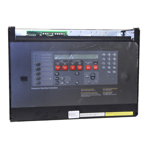
Figure 1: User interface
3.1 Control unit buttons
3.1.1 ACK
Pressing the ACK key performs the following actions:
• Acknowledges every abnormal point in the selected system category, for example fire, supervisory or trouble
• Silences the piezo sounder
• Changes the flashing LEDs to steady
• Sends acknowledge messages to the history file.
If all three events are present, the FACU acknowledges the events in the following order:
1. Alarm
2. Supervisory
3. Trouble
The FACU also scrolls through an active list in the same order. While viewing the active list, if any events of higher priority occur, for
example, alarms in case of supervisory or trouble list, or alarms and supervisory in case of trouble list, the list shows high priority events
after you have viewed all the events in that list. In order to view the new event, press the ESC key and then press the ACK key. The FACU
displays the unacknowledged events in the defined priority.
The ACK key does not have any effect on the NACs.
3.1.2 SILENCE
If an alarm exists, press the SILENCE key to turn off all silenceable outputs, such as NACs. The system turns on the ALARM SILENCED LED
and displays the alarm silenced message on the LCD screen.
Hold the SILENCE key for more than 10 seconds to perform a DACT test and send the test signal to the receiving station.
page 5 579-1401 Rev A
2008 Foundation Series Fire Alarm Control Unit Operation Guide

3.1.3 RESET
Press and release the RESET key to complete the following actions:
• Reset all alarm notification appliances and controls.
• Remove alarms from the alarm list after restoring the respective devices to normal state.
• Silence all silenceable outputs.
• Return the system to a normal state, provided that no alarm, supervisory or trouble conditions are present.
Hold the RESET key for more than 10 seconds to perform a Lamp test by turning on all LEDs, control unit piezos and the LCD display. If
any alarm or trouble exists after a reset, the notification appliance circuits sounds again.
If you press the RESET key when the control unit is normal or not in alarm, then the control unit performs a hardware (HW) reset.
3.1.4 WALK TEST
Press the WALK TEST key to activate the walk test feature and turn on the control unit piezo. The control unit piezo turns on and the
TROUBLE LED starts flashing. For more information, see Walk test.
3.1.5 MENU
Press the MENU key to get to the top of the main menu structure, unless you are in the programming menu.
3.1.6 UP and DOWN
Press the UP and DOWN keys to scroll through the system lists, such as the historical log and point database.
3.1.7 LEFT and RIGHT
Press the LEFT and RIGHT keys to scroll through screens with multiple options. The keys advance the focus, indicated by the square
brackets [], from field to field.
3.1.8 ESC
Press the ESC key to exit a menu or display and return to the top level structure. The ESC key exits the menu structure one level at a time.
In some cases, the ESC key returns the operator directly to the top level menu.
3.1.9 ENTER
Press the ENTER key to confirm your selection. Press the ENTER key in the programming screen to accept that the information on the
display is correct. Select an event and press the ENTER key to view additional information.
3.2 LED indicators and piezo
Table 1: LED indicators
Component LED color Description
Fire LED Red Indicates a fire alarm when flashing and an acknowledged alarm when steady on.
Supervisory LED Yellow Indicates a supervisory condition when flashing and an acknowledged condition when steady on.
Trouble LED Yellow Indicates a trouble condition when flashing, and an acknowledged trouble when steady on.
Alarm Silenced LED Yellow Indicates an alarm has been silenced when steady on.
AC Power LED Green Indicates AC power is applied to the control unit when steady on.
Battery Trouble LED Yellow Indicates a battery trouble state when flashing and an acknowledged trouble when steady on.
Ground Fault LED Yellow Indicates a ground fault state when flashing and an acknowledged trouble when steady on.
Disabled LED Yellow Indicates the system has been disabled when flashing and an acknowledged trouble when steady on.
Piezo - Emits tones during alarm, supervisory and trouble conditions.
Tone-alert pulses for an alarm condition, and is on steady for a trouble or supervisory condition.
page 6 579-1401 Rev A
2008 Foundation Series Fire Alarm Control Unit Operation Guide

4 Operations
4.1 Normal operation
Normal condition is the standard condition of operation. When no alarm or trouble conditions exist, the control unit's operator interface
shows the following:
• The green AC POWER LED is on steady
• All other control unit indicator LEDs and local piezo are off
• All NACs are off
• All relays are in their normal state
• The control unit's LCD displays the following output:
SYSTEM NORMAL
12:35:15 PM 20/09/18
4.2 Fire alarm operation
An alarm condition occurs when an initiating device, such as a smoke detector or heat detector, activates. When an alarm occurs, the
control unit performs the following actions:
• The red FIRE LED starts flashing.
• The local piezo produces a pulse tone.
• Alarms latch are not cleared automatically.
• Activates the general alarm relay and NACs output as programmed by the user.
• Communicates the alarm condition to the central station and the remote station, if programmed.
• The system stores an alarm event in the history file.
• If the Display First Alarm option is selected, the display provides information about the first alarm in the system without operator
intervention.
• If the Display First Alarm option is not selected, the control unit LCD shows the overall system status:
FIRE | SUPV | TRBL
01 | 00 | 01
When you press the ACK key, the following actions occur:
• The FIRE LED illuminates steady.
• The local piezo turns off.
• The system stores an acknowledged event in the history file.
• The system displays specific data on the location of the alarm. For example:
CORE 1 MEZZANINE
FIRE 1/2
When you press the SILENCE key, the following actions occur:
• The yellow ALARM SILENCED LED turns on. There is no effect on any other LEDs.
• The system turns off all devices and circuits that are programmed to turn off when the SILENCE key is pressed. For example, when
you press the SILENCE key, the NACs that are configured as SSIG or relays that are configured as SRELAY turn off.
• The system stores an alarm silence event in the history file
• If a subsequent alarm occurs, the FIRE LED will start flashing, the Alarm Silenced LED turns off and the NACs and the local piezo
resounds.
Note: When you press the SILENCE key, a message screen appears indicating
Silence Completed
page 7 579-1401 Rev A
2008 Foundation Series Fire Alarm Control Unit Operation Guide

Press any key.
To exit from this screen, press any key on the keypad.
When you press the RESET key, the following actions occur:
• The screen displays the RESET IN PROGRESS message.
• The system returns to its normal state, if an alarm condition has been cleared and the FIRE LED turns off.
• All latched circuits reset automatically.
• Turns off all devices and circuits that are programmed to turn off when this key is pressed. For example, when you press the RESET
key, the NAC’s configured as RSIG and relays configured as alarm relay RRELAY turn off.
• The system stores a system reset event in the history file
• If a device remains in alarm state during the reset period, the system reset is aborted, and the system remains in the alarm state. The
display shows the devices that remain in alarm.
Note: On pressing the RESET key, a message screen appears indicating Reset in Progress and Press any key. To exit from
this screen, press any key on the keypad.
After the reset is completed, a message screen appears indicating Reset Completed and Press any key. To exit from this screen,
press any key on the keypad.
4.3 Supervisory operation
A supervisory condition occurs when an initiating device activates. An example is a smoke detector or a heat detector that connects to an
IDC with a supervisory (SUPV) function type.
When a supervisory condition occurs, the control unit performs the following actions:
• The yellow SUPV LED starts flashing.
• The local piezo produces a steady tone.
• Activates the general supervisory relay and other outputs if programmed by the user.
• Communicates the supervisory condition to the central station and the remote station, if programmed.
• The system stores a supervisory event in the history file.
When you press the ACK key, the following actions occur:
• The SUPV LED illuminates steady.
• The local piezo turns off.
• The system stores an acknowledged event in the history file.
• Depending on the system design or programming options, a supervisory point can be one of the following:
- Non-latching: The indicators, such as the LED and piezo, turn off automatically when the condition clears.
- Latching: The control unit must be reset to clear the supervisory condition.
4.4 Trouble operation
When the trouble condition occurs, the control unit performs the following actions:
• The yellow TROUBLE LED starts flashing.
• The different LEDs indicate the following specific troubles:
- If there are troubles in an IDC zone, the respective zone's yellow TROUBLE LED starts flashing.
- If there is AC loss, the green AC POWER LED turns off.
- If there are battery faults, the yellow BATTERY TROUBLE LED starts flashing.
- If there are ground faults, the yellow GROUND FAULT LED starts flashing.
- If the system is disabled, the yellow DISABLED LED starts flashing.
• The local piezo produces a steady tone.
• The system activates the general trouble relay and other outputs if programmed by you.
• Communicates the trouble condition to the central station and the remote station, if programmed.
• The system stores a trouble event in the history file.
page 8 579-1401 Rev A
2008 Foundation Series Fire Alarm Control Unit Operation Guide

When you press the ACK key, the following actions occur:
• The TROUBLE LED and all other specific trouble indicators illuminate steady.
• The local piezo turns off.
• The system stores an acknowledged event in the history file.
The following are latch-able troubles:
1. NAC over current Trouble. NAC short during an alarm condition. To recover, follow these steps:
- Clear the alarm condition and reset the panel
- Reset the panel again to clear the trouble
2. Open trouble on IDC Class-A circuit. To recover, reset the panel to clear the trouble
page 9 579-1401 Rev A
2008 Foundation Series Fire Alarm Control Unit Operation Guide

5 User access levels
There are three access levels for logging into the control unit. The lowest user access level 1, is the default.
Certain operator functions are passcode-protected at different access levels.
Table 2: Access levels and functions
Functions Access level
1
Access level
2
Access level
3
Acknowledge Events (Alarm, Supervisory, Trouble) Yes Yes Yes
Alarm Silence Yes Yes Yes
System Reset Yes Yes Yes
View Historical Logs Yes Yes Yes
View Point Information Yes Yes Yes
Lamp Test Yes Yes Yes
View Diagnostics Yes Yes Yes
DACT Manual Test Yes Yes Yes
Software Revision Yes Yes Yes
Display Time Yes Yes Yes
Set Time/Date No Yes Yes
Point Control No Yes Yes
Enable and Disable points No Yes Yes
City Disconnect No Yes Yes
Control Point, Elevator and Door Holder Bypass No Yes Yes
Custom Label editing No Yes Yes
Run Diagnostics No Yes Yes
WALK TEST No Yes Yes
Clear Historical Logs No Yes Yes
Upload and Download No No Yes
Cold and Warm Start No No Yes
Programming No No Yes
Note: You can change the default access levels of all functions except for Programming.
page 10 579-1401 Rev A
2008 Foundation Series Fire Alarm Control Unit Operation Guide

6 Logging in or logging out of the control unit
• To perform any of the functions protected at level 2 or above, you need to log into the control unit using a passcode.
• After you complete a task at a certain access level, logout to return the access level to level 1 to prevent unauthorized operation.
• When you are logged in at level 2 or above and no control unit keys are pressed for more than 10 minutes, the control unit
automatically returns the system to level 1.
• Logging in at level 3 causes a service mode trouble that you can only clear by restarting the control unit.
Note: To login at access level 2 or 3 for the first time, you need to change the default passcodes or else the control unit will not proceed
further. For more information, see Changing the default passcode of the control unit.
6.1 Changing the default passcode of the control unit
To change the default passcode of access level 2, complete the following steps:
1. Press MENU.
2. Press DOWN until you reach the [Login/Logout] option.
3. Press ENTER and the control unit displays the following:
Access Level 1
<ENTER> = [Login]
4. Press ENTER and the control unit displays the following:
Access Level 1
Passcode: *[0]
5. Enter the default passcode for level 2, 2000 , and the following appears:
Change Level 2
Default Passcodes
6. Enter a new four digit passcode when the control unit displays the following:
Level 2
Passcode [0]***
Note: New four digit passcodes can be any numeric number other than the default passcodes of level 2 and level 3. New
passwords cannot be set to 0000 .
7. Re-enter the passcode when the control unit displays the following:
Re-Enter to confirm
Passcode: [0]***
8. After you confirm the passcode, press ENTER to save job, the control unit displays the following:
Passcode updated
Note: Repeat this procedure to change the default passcode of access level 3. The default passcode for access level 3 is 3000 .
If you forget the access level 3 password, you can reset the password using the P21 jumper.
page 11 579-1401 Rev A
2008 Foundation Series Fire Alarm Control Unit Operation Guide

6.2 Logging in at access level 2 or 3
To log in at access level 2 or 3, complete the following steps:
1. Press MENU.
2. Press UP/DOWN until you reach the [Login/Logout] option.
3. Press ENTER and the control unit displays the following:
Access Level 1
<ENTER> = [Login]
4. Press ENTER and the control unit displays the following:
Access Level 1
Passcode: *[0]
5. Enter the correct four digit passcode and the control unit displays the following:
*Login Successful*
Access Level 2
or
Access Level 3
page 12 579-1401 Rev A
2008 Foundation Series Fire Alarm Control Unit Operation Guide

7 Auto-program
The Auto-Program option provides the ability to quickly and automatically program the control unit's components and features for
general alarm operation. It automatically scans the serial communication channel, adding any annunciators found, and city circuit module.
Note: The Auto-Program is protected at access level 3. To perform an Auto-Program operation, login the operator at access level 3.
The Auto-Program option can perform the following actions:
• Reconfigure all hardware.
• Add new hardware.
• Restore factory defaults.
• Accept defaults.
• Edit the system's option settings.
Note: When using the Auto-Program option be aware of the following:
• The control unit does not operate as a fire alarm system during auto-programming.
• You need to manually program DACT information, such as phone numbers and account information.
7.1 Creating a new configuration
This option starts the control unit with a new configuration. If a previous configuration is present and this option is selected, it erases the
previous configuration and creates a new one with the currently connected hardware.
1. Press MENU.
2. Use the UP or DOWN keys until the [Auto-Program] menu item is displayed.
3. Press ENTER. The control unit displays the following:
FIRE ALARM
SUSPENDED
After a few seconds, the control unit displays the following:
<ENTER> to PROGRAM
<EXIT> to CANCEL
4. Press ENTER and the control unit displays the following:
<ENTER> = Accept
AP: [Reconfig All]
5. Press ENTER, the following warning message appears indicating that this action deletes the current configuration:
<ENTER> to Continue
*May CHANGE setting*
The display indicates the progress of the Auto Program operation.
6. Press the ESC key when the auto-programming operation is complete. The control unit displays the following:
JOB HAS CHANGED
[Cont] Dscrd Save
7. Use the LEFT/RIGHT key to move the cursor to one of the following three options. Press ENTER to select an option.
- Select Cont to continue editing the configuration.
- Select Dscrd to discard changes made during the programming session and restore the original configuration, if possible.
- Select Save to save the new job configuration.
8. Select [Save] and press ENTER. The control unit displays the following:
<ENTER> to SAVE JOB
<ENTER> = SAVE
** Saving JOB **
page 13 579-1401 Rev A
2008 Foundation Series Fire Alarm Control Unit Operation Guide

Note: When you save the configuration, the control unit automatically restarts and runs through its self-test procedure.
page 14 579-1401 Rev A
2008 Foundation Series Fire Alarm Control Unit Operation Guide

7.2 Detecting new hardware
This option adds newly found devices and cards to the existing configuration.
1. Press MENU.
2. Use the UP or DOWN keys until you reach the [Auto-Program] menu item.
3. Press ENTER. The control unit displays the following:
FIRE ALARM
SUSPENDED
After a few seconds, the control unit displays the following:
<ENTER> to PROGRAM
<EXIT> to CANCEL
4. Press ENTER and use the UP or DOWN keys until [DETECT NEW] is displayed.
5. Pressing ENTER. A warning message appears, indicating that this action deletes the current configuration.
6. When the auto-programming operation is complete, press the ESC key. The control unit displays the following:
JOB HAS CHANGED
[Cont] Dscrd Save
7. Select [Save] and press ENTER to save the configuration.
7.3 Restoring factory settings
This option restores the 2008-9101 control unit to its original, factory default configuration. All custom programming including IDCs, NACs,
relays, system options and access levels are erased from the configuration.
1. Press MENU.
2. Use the UP or DOWN keys until you reach the [Auto-Program] menu item.
3. Press ENTER. The control unit displays the following:
FIRE ALARM
SUSPENDED
After a few seconds, the control unit displays the following:
<ENTER> to PROGRAM
<EXIT> to CANCEL
4. Press ENTER and use the UP or DOWN keys until you reach the [FACTORY DEFAULT] option.
5. Press ENTER. A warning message appears indicating that this action deletes the current configuration. The control unit
automatically restarts after the LCD displays the following message:
RESTORING DEFAULT
page 15 579-1401 Rev A
2008 Foundation Series Fire Alarm Control Unit Operation Guide

7.4 Accepting defaults
This option restores only system options and access levels to their original factory default configuration.
1. Press MENU.
2. Press UP or DOWN until you reach the [Auto-Program] menu item.
3. Press ENTER. The control unit displays the following:
FIRE ALARM
SUSPENDED
After a few seconds, the control unit displays the following:
<ENTER> to PROGRAM
<EXIT> to CANCEL
4. Press ENTER and press UP or DOWN until [ACCEPT DEFAULT] is displayed.
5. Press ENTER. A warning message appears indicating that this action deletes the current configuration. The LCD displays the
message:
Default Restored
The control unit displays the following:
<ENTER> to PROGRAM
<EXIT> to CANCEL
6. Press the ESC key and the control unit displays the following:
JOB HAS CHANGED
[Cont] Dscrd Save
7. Select [Save] and press Enter to save the configuration.
page 16 579-1401 Rev A
2008 Foundation Series Fire Alarm Control Unit Operation Guide

7.5 Editing system options
To set the control unit's automatic functions, edit the system options by completing the following steps:
1. Press MENU.
2. Use the UP or DOWN keys until you reach the [Auto-Program] menu item.
3. Press ENTER. The control unit displays the following:
FIRE ALARM
SUSPENDED
After a few seconds, the control unit displays the following:
<ENTER> to PROGRAM
<EXIT> to CANCEL
4. Press ENTER and use the UP or DOWN keys until you reach the [SYS OPTIONS] option.
5. Press ENTER. The first prompt appears similar to the following:
<ENTER>=Accept
Opt: [Time/Date]
6. Use the UP and DOWN keys to review the options. Press ENTER when the option is set to the appropriate value. For more
information about each system option, see Table 3.
Table 3: System options
Option Settings
Time/Date format Choose 12- or 24-hour format
Reminder (Active status
reminder)
Choose:
ON or OFF (default = ON)
Set reminder interval (1 to 12 hours; default = 8 hours)
Set signal duration (0 to 60 seconds; 0=on until ack; default=0)
Inhibit (Alarm silence/reset
inhibit)
Choose a timer range from 0 to 60 minutes; (default=0 - no inhibit)
Alarm cutout Choose a timer range from 0 to 60 minutes; (default=0 - no cutout)
Alarm doors Choose a timer range from 0 to 60 seconds; (default=0 - immediate)
AC doors Choose a timer range from 0 to 60 minutes; (default=5 minutes)
Depl batt cut (Depleted
battery cutout)
Choose ON or OFF; default = OFF
City circuit Choose ON or OFF; default = OFF
Disp 1st Alm (Display 1st
alarm)
Choose ON or OFF; default = OFF
AHJ reset If this option is not selected, a device or point must be in normal state to enable a system reset.
When this option is selected, a device or point only needs to be, not in an alarm state, for the system to be
reset. For example, a point can be in trouble.
NFPA NAC When this option is selected, the horns and strobes on the QALERT NACs, turn off when alarm silence is
activated. If the option is not selected, the strobes turn off upon completion of system reset.
Cross zone Selectable for each alarm group. Selects whether one alarm or more than one alarm is required to trigger
outputs for that alarm group.
Alarm Groups programmed as Cross Zone must not contain any devices programmed with the VSMOKE Input
Function Type.
Edit passcodes Enables you to change the existing passwords.
7.6 Restoring default system options
Use this option to restore the factory default options. Selecting this option deletes any edits that were performed in the Edit System
Options menu, but does not effect any card or point programming.
page 17 579-1401 Rev A
2008 Foundation Series Fire Alarm Control Unit Operation Guide

8 Default programming assignments
8.1 IDC, NAC, and relay default function types
For information about the default function types assigned by the auto programming process to IDC, NAC and relays, see Table 4.
The function type determines how the device operates. For example, a function type of SSIG or SRELAY means the device is on until an
alarm silence is performed.
The function type is a programmable attribute that you can manually change.
Table 4: Default function types of IDC, NAC and relay
Circuit Default function type
IDC1-8 Fire
NAC1 and NAC2 QALERT
AUX1 (Relay 1) Common Fail-Safe Trouble (non-programmable)
AUX2 (Relay 2) Common Alarm, On Until Reset (programmable)
AUX3 (Relay 3) Common Supervisory (Programmable)
AUX4 (Relay 4) Common Trouble (Programmable)
8.2 NAC, relay, and signal circuit output mode assignments
For the default output method, for example, steady or temporal assignments for the NAC and relay circuits, see Table 5.
The output mode is a programmable attribute that you can manually change.
Table 5: Default operating modes of NAC, relay and signal circuit outputs
Circuit Default function type
NAC1 and NAC2 Temporal code, is a three pulse coding pattern consisting of three 1/2 second pulses, each separated by 1/2
second silence. Each group of three pulses is separated by 1.5 seconds of silence
Relay 1 to 4 Steady on
SIGNAL modules Steady on
8.3 DACT defaults
The defaults for the DACT are as follows:
• Tone else pulse dialing
• AC Fail reporting delay is 2 hours.
• Reporting format is contact ID (CID).
• Primary and secondary phone number. There are no values for the primary and secondary phone numbers or account codes.
• Default event codes are shown in Table 6.
Table 6: Default CID event codes
Function type Fire Supervisory Trouble Function type Fire Supervisory Trouble
FIRE 110 - 330 SUPV - 200 330
WATER 113 - 330 UTIL - - 330
HEAT 114 - 330 TROUBLE - - 330
DUCT 116 - 330 VSMOKE 111 - 330
PULL 115 - 330 LATSUPV - 200 330
SMOKE 111 - 330 STYLEC 110 - 330
SO - 200 330 DRILL - - 330
WSO 110 200 330 OTHER TRBL
(see note)
- - 330
Note: Any other trouble not specifically mentioned would have a code of 330, for example, a trouble on an output device would report an
event code of 330.
page 18 579-1401 Rev A
2008 Foundation Series Fire Alarm Control Unit Operation Guide
Table of contents
Other Simplex Control Unit manuals

Simplex
Simplex 2050 User manual

Simplex
Simplex 2004 Series User manual

Simplex
Simplex 4100-6069 User manual

Simplex
Simplex 2050 User manual

Simplex
Simplex 4100-5101 User manual

Simplex
Simplex MINIPLEX 4100ES Series User manual

Simplex
Simplex 2008 Series User manual

Simplex
Simplex 4001-9810 User manual

Simplex
Simplex 2004 Series User manual

Simplex
Simplex 4090-9116 User manual
Popular Control Unit manuals by other brands

RAYLASE
RAYLASE SP-ICE-1 PCI/e PRO Hardware manual

Nibe
Nibe SAM 40 Installer manual

Signature Hardware
Signature Hardware RYLE 934424 installation instructions

Cotek
Cotek SR series user manual

Zeta Alarm Limited
Zeta Alarm Limited SmartConnect SCM-NM instruction manual

Zator
Zator MZL100 User and maintenance manual