Simplex 4604-9201 Quick guide

II.Simplex
4604-9201 Graphical LCD Annunciator
Installation and Configuration Instructions
CaUtiOIIS
andwarnings
DONOTINSTALLANYSIMPLEXPRODUCTTHATAPPEARS
DAMAGED.
Upon unpacking your Simplex product, inspect the contents of the
carton for shipping damage. If damage is apparent, immediately file a claim with the
carrier and notify Simplex.
If>-
ELECTRICAL HAZARD
- Disconnect electrical power when making any internal
ii // adjustments or repairs. Servicing should be performed by qualified Simplex
Representatives.
Introduction
RADIO FREQUENCYENERGY
- This equipment generates, uses,and can radiate
radio frequency energy and if not installed and used in accordance with the instruction
manual, may cause interference to radio communications. It has been tested and found
to comply with the EMC Requirements of Standard GB47 17-93 of the People’s
Republic of China, as well asthe European Economic Community (EEC) standards
for EMC (EN50082-1, 1992) and EMI (EN55022, Class A), and is designed to
provide reasonable protection against such electro-magnetic interference when
operated in a commercial environment. Operation of this equipment in a residential
area is likely to cause interference in which casethe user at his own expense will be
required to take whatever measures may be required to correct the interference.
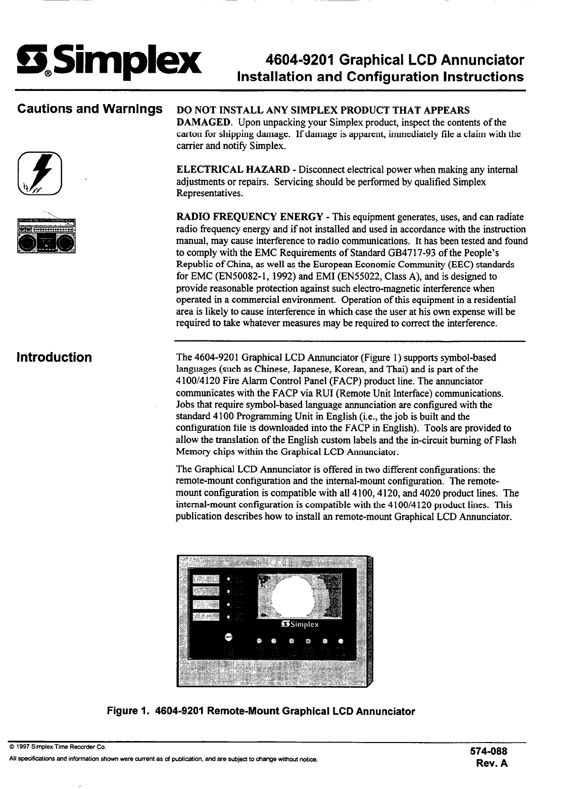
The 4604-9201 Graphical LCD Annunciator (Figure 1) supports symbol-based
languages (such as Chinese, Japanese, Korean, and Thai) and ispart of the
4100/4 120 Fire Alarm Control Panel (FACP) product line. The annunciator
communicates with the FACP via RUI (Remote Unit Interface) communications.
Jobs that require symbol-based language annunciation are configured with the
standard 4100 Programming Unit in English (i.e., the job isbuilt and the
configuration file is downloaded into the FACP in English). Tools are provided to
allow the translation of the English custom labels and the in-circuit burning of Flash
Memory chips within the Graphical LCD Annunciator.
The Graphical LCD Annunciator is offered in two different configurations: the
remote-mount configuration and the internal-mount configuration. The remote-
mount configuration is compatible with all 4100,4120, and 4020 product lines. The
internal-mount configuration is compatible with the 4100/4 120 product lines. This
publication describes how to install an remote-mount Graphical LCD Annunciator.
Figure 1. 4604-9201 Remote-Mount Graphical LCD Annunciator
0 1997 Simplex Time Recorder Co.
574-088
All specifcations and information shown were current as of publication. and are subjed to charge without notice.
Rev. A
firealarmresources.com

Requirements
Installation Requirements
Wiring Precautions
The 4604-920 1Graphical LCD has the following installation requirements:
l
The 4604-920 1Graphical LCD Annunciator can be semi-flush-mounted or
surface-mounted.
l
A maximum of 31 annunciators can be connected to a 4 100 FACP.
l
When wiring an annunciator, at least 18 AWG twisted wire is required.
. If twisted-shielded pair wire is used, the shield must be grounded in the
4100 FACP.
The following wiring precautions should be observed when wiring the Graphical
LCD Annunciator.
. All wiring must be copper-conductor.
. Wire lengths in excessof those listed in Tables 1 through 5 are not permitted.
l
If shielding is used, you must observe the following:
- Metallic continuity of the shield must be maintained throughout the entire
length of the cable.
- The entire length of the cable must have a resistance greater than 1 Megohm
to earth ground.
- The shield must connect to a SHIELD terminal at each annunciator, and
must be grounded only at the main panel.
l
If shielded wire isnot used, wire must be run in metallic conduit or equivalent.
l
Underground wiring must be free of water.
l
Wires must not be run through elevator shafts.
l
Wire runs in plenums must be in conduit.
l
Splicing ispermitted provided that:
- All such connections are soldered (rosin-core solder), crimped in metal
sleeves, or encapsulated with an epoxy resin.
- When solder or crimped metal sleeves are used, the junction is insulated
with a high-grade electrical tape assound as the original insulating jacket.
- The shield’s continuity is maintained throughout the cable’s length.
. The annunciator box must be connected to Earth Ground or building steel.
l
Only system wiring can share the same conduit.
Continued on next page
2
firealarmresources.com

Requirements,
Continued
Wiring Precautions
(Continued)
l
A Graphical LCD Annunciator cannot be used with wiring that goes outside the
building (above or below ground) unless overvoltage suppression isprovided at
both ends. Communication and power wiring must meet the following
conditions.
- Use Simplex Model 208 l-9044 Overvoltage Protectors. (2OOmA or less).
No restrictions on wire routing. Maximum wire length is 2500 feet.
- Use Simplex Model 2081-9027 (2OOmAmax) or 2081-9028 (5A max)
Isolated Loop Circuit Protectors.
- For Underground Wiring, select the appropriate isolated loop circuit
protector. The circuit
wiring must
be run in a separate parallel wiring
trough, separated from any commercial power distribution wiring.
l
For Overhead Wiring, select the appropriate isolated loop circuit
protector. The wiring is limited to one contiguous property and the
total wire length must not
exceed
2500 feet. The circuit
wiring must
be
run on separate poles, separated from any poles supporting commerical
power distribution wiring. The circuit wiring
must
be run in parallel
with direct relation to the commercial power distribution. The
separation
is
a minimum distance (whichever isgreater) of 100 feet, or
the maximun span between any two adjacent poles of either the system’s
circuit or the commericial power distribution circuit.
l
For maximum wire lengths when using protectors, see Tables 2,4,
and 5.
Continued on next page
firealarmresources.com

Requirements,
Continued
4100/4120 to Graphical LCD Seriall Communications
Annunciator Wiring
l
Annunciator terminal blocks accommodate 12 to 18 AWG wire.
l
When used with audio riser wiring, telephone wiring, and/or 4 120 Network
wiring, the communication lines must be twisted-shielded pair.
l
Parallel configurations are acceptable where the total distance of all series and/or
parallel runs do not exceed the maximum permitted distance. (See Tables 3
through 5.)
Operating Power
l
Annunciator terminal blocks accommodate 12 to 18 AWG wire. (See Tables 1
and 2.)
l
Operating power must be provided by the system power supply. All circuits are
power limited.
Continued on next page
4
firealarmresources.com

Requirements,
Continued
Maximum Wire Lengths
Maximum wire lengths for the Graphical LCD Annunciator are shown in
Tables 1through 5.
Power
Power wiring is shown in Tables 1and 2.
Table 1. With 2081-9044 Overvoltage Protectors
11
Table 2. Without Transient Suppression (or with 2081-9028
Isolated Loop Circuit Protectors)
I
Total
Current I 12 AWG 14 AWG 16AWG 1 18AWG 1
I
O.lOOA I 25OOfi 25OOfi 2500ft 1 25OOft 1
I
0.200A I 25OOft 25OOfl 2500ft 1 234Ofi 1
0.300A 2500ft
0.400A 25OOfi 25OOft 156Ofi
1875fi 1170ft
15ooft 935fi
125Oft 78Ofl
2500ft
25OOfi
2400A
I
0.500A I 2500ft
I
0.600 A I 25OOft 2000A
171oft 107Oft 1 665fi 1
15oofi 93Oft 1 58Ofi 1
1330A 83Oft 1 52Ofi 1
I
l.OOOA I 1875ft 1200A 75Ofi 1 465fi 1
1ovofi 680ft 1 425fi 1
1OOOA 625fi 1 390ft 1
Continued on next page
5
firealarmresources.com

Requirements,
Continued
Maximum Wire Lengths
(Continued) Communications
Communications wiring is shown in Tables 3 through 5.
Table 3. With 2081-9044 Overvoltage Protectors
Table 4. Without Transient Supression
(or with 2081-9028 Isolated Loop Protecltors)
I
14AWG I 16 AWG I 18 AWG
(2.081 mm) (1.309 mm) (0.823 mm) I
Table 5. With 2081-9027 Isolated Loop Circuit Protectors
12AWG 14 AWG 16 AWG 18 AWG
(3.309 mm) (2.081 mm) (1.309 mm) (0.823 mm)
Note: A maximum quantity of four 2081-9044 Overvoltage Protectors and four
2081-9028 Isolated Loop Circuit Protectors are permitted on any single
communications loop.
Continued on next
pa@_
6
firealarmresources.com

-
Requirements,
Continued
Power Requirements The Graphical LCD Annunciator has the following power requirements.
. Voltage
- 24 VDC Power Supply: 24 VDC nominal (18 VDC to 32 VDC)
l
Current
- Backlight first ON: 210 mA peak from the 24 V supply
- Nominal: 160 mA maximum from the 24 V supply
Environmental Limitations The Graphical LCD Annunciator has the following environmental limitations.
l
Temperature
- Operating Temperature: 25” C (77’ F)
- Operating Range: 0” C to 50” C (32” F to 122’ F)
l
Humidity
- Operating Range: 90 to 95 percent non-condensing at 40” C (+ 2“ C)
7
firealarmresources.com

Switches, Jumpers, and Indicators
Switches
The Graphical LED Annunciator card has the folllowing switches:
l
Reset Switch (SWl)
- Momentarily press SW1 (Figure 6) to perform a manual
warm-start of the 4100 Graphical LCD Annunciator. The annunciator
microcontroller isreset assoon as you press the switch.
.
Address Switch (SW3)
- SW3 (Figure 6) is an S-position DIP switch used to set
address and baud rates for RUI channel communication.
.
Key Switch (SWZ)
- SW2 is available on remote units only and may be
programmed to either lockout the front panel or lockout only select membrane
switches. When the key switch is placed into the “enable” position, all lockout-
programmed membrane switches are active. When the key switch is in the
“disable” position, all lockout-programmed membrane switches are disabled.
When the key switch is returned to the “disable” position, the annunciator
performs a lamp test.
Jumpers
LED Indicators
The Graphical LED Annunciator has the following jumpers:
Download Control Jumper (Pl)
- Place Jumper Pl (Figure 6) in position 2-3 beforc
downloading data corn the 4100 Programming Unit (via the RS232 port). After
downloading, return the jumper to the normal 1-2 position for annunciator tasks.
Table 6 lists the Graphical LED Annunciator LED indicators.
Table 6. LED Indicators
8
firealarmresources.com

Inputs and Outputs
Card Connections Table 7 lists the Graphical LCD Annunciator card connections.
Table 7. Graphical LCD Annunciator Card Connections
Designation Connector Function
P2 Membrane Keypad Connector The front panel membrane
keypad is attached to the
Graphical LCD Annunciator
card at connector.
P3 LCD Backlight Connector Switched power to the LCD
backlight tube is provided via
P3.
P4 RS-232 Connector The RS232 port is used for
downloading a Language
database, or performing RUI
comm analysis.
P5 Annunciator Power Connector Used only on internal-mount
units.
P6 RUI Communications
Connector RUI Communications is
provided to the Graphical LCD
Annunciator via P6 (intemal-
mount unit only).
P7 LCD Data Connector Connects the LCD assembly
to the CPU board.
TBI
TB2
Annunciator Power Terminal
Block
Annunciator Power Terminal
Block
Power is provided to an
remote-mount unit via TBI .
RUI Communications is
provided to the Graphical LCD
Annunciator via TB2 (remote-
mount unit only).
firealarmresources.com

Installation
Related Documentation
The following is a list of additional documentation that may aid you in the
installation of the Graphical LCD Annunciator.
l
4IOO+/412O/UT System Card Installation Instructions ................... 574-038
l
4020 Field Wiring Diagram .............................................................
841-842
l
4100 Field Wiring Diagram .............................................................
841-731
l
4100 Field Wiring Diagram .............................................................
841-995
l
Graphical LCD Annunciator Field Wiring Diagram .......................
842-025
Unpacking the Annunciator
Unpack the annunciator using the following procedure.
1. Lay the shipping container on a flat surface near the back box where the
installation isto take place.
2. Carefully remove the plastic bands from the container and remove the container
cover.
3. Remove the packing material from the Graphical LCD Annunciator and remove
the unit from the shipping container.
4. Lay the unit on a flat surface.
Install the back box using the following procedure.
1. Connect aproperly-grounded Static Ground Strap Assembly to your wrist.
2. Remove the four (4) screws holding the metal retainer and set them aside.
3. Remove the retainer from the assembly and set it aside.
4. Remove the four (4) screws holding the electronics assembly and set them aside.
5. Remove the electronics assembly from the back box and set it aside.
6. Remove the Static Ground Strap Assembly from your wrist.
7. Place the back box on the wall over the junction box and mark the wall where
the top back box support screws will be placed.
8. Pull the wiring through the back box knockout.
9. Thread the wiring through the strain relief and hang over the front edge of the
back box. (See Figure 2.)
Continued on next pag:
IO
firealarmresources.com

Installation,
Confinued
Installing the Back Box
(Continued)
EARTH GROUND STUD
10.
11.
12.
13.
14.
15.
Using the hardware provided, insert a No. 8 mounting screw in the wall at the
positions marked in Step 7.
Tighten the two No. 8 mounting screws while leaving an l/8-inch gap from the
seated position of each screw.
Carefully place the top teardrop holes of the back box onto the two screws that
you tightened in Step 11. Allow the back box to hang from the screws (you will
tighten them completely later).
Insert the remaining mounting screws through the screw holes in the back box.
(See Figure 3.)
Using the information in Table 8, securely tighten all mounting screws.
Connect the Earth Ground wire to the back box. Refer to the notes on the
842-025 Field Wiring Diagram (supplied) for more information.
CAUTION:
Make certain that you do not pinch any wiring behind the back box
when mounting as damage may occur to the equipment.
Figure 3. Installing the Screws
Table 8. Recommended Torque for Mounting Hardware
Continued on next page
11
firealarmresources.com

Installation,
Confinued
Wiring the Annunciator Wire the annunciator in the following manner.
1. Connect a properly-grounded Static Ground Strap Assembly to your wrist.
2. Terminate the annunciator’s power and COMM lines on the electronics assembly
in the following manner. (Refer to the Field Wiring Diagrams and Figure 4.)
Power (TBI)
TB l-l = From +24V of 4100 Power Supply or +24V of previous annunciator.
TB l-2 = To +24V of next annunciator.
TB l-3 = From 24C of 4100 Power Supply or 24C of previous annunciator.
TB l-4 = To 24C of next annunciator.
Comm (TB2)
TB2-1 = +DATA from 4 100 or previous annunciator.
TB2-2 = +DATA to next annunciator.
TB2-3 = -DATA from 4 100 or previous annunciator.
TB2-4 = -DATA to next annunciator.
TB2-5 = SHIELD from 4 100 or previous annunciator
TB2-6 = SHIELD to next annunciator.
Figure 4. Location of TBI and TB2
Continued on next page
12
firealarmresources.com

Installation,
Continued
Mounting the Electronics
Assembly Mount the electronics assembly in the following manner.
1. Place the electronics assembly on the back box. (See Figure 5.)
CAUTION: Make certain that you do not pinch any wiring behind the electronics
assembly when mounting asdamage may occur
to the equipment.
2. Align the four holes on the back box with the four holes on the
electronics assembly.
3. Insert the four screws that you removed earlier into the holes in the back box.
4. Using the information in Table 8, securely tighten these screws.
MOUNTING SCREWS
Figure 5. Mounting the Electronics Assembly
Continued on next page
13
firealarmresources.com

Installation, Confinued
Setting the Annunciator
Address and Baud Rate
:sw3 I
. -
0
I
. ADDRESS
SW1
0
I:::::I
199QQ9Ql
I
RESET
RESET DOWNLOAD +24 24~ +COM -CONI SHLD
Setthe annunciator’s address and baud rate using DIP Switch SW3 (Figure 6).
(Refer to Appendix A for the Annunciator Address Chart.)
CONTRAST ADJUST
BOlTOM OF ELECTRONICS ASSEMBLY
(SHOWN SET FOR ADRESS BAUd RATE
6 AND 9600 BAUD)
Figure 6. Setting the Annunciator’s Address and Baud Rate
Continued on next pag-
14
firealarmresources.com

IInstallation,
Continued
Mounting the Retainer Mount the retainer in the following manner.
1. Place the retainer over the electronics assembly.
2. Align the four (4) holes in the retainer with the matching holes in the
back box.
3. Insert the four (4) screwsthat you removed earlier into the holes in
the retainer.
4. Using the information in Table 8, securely tighten these screws.
RETAINER SCREWS
Figure 7. Mounting the Retainer
15
firealarmresources.com

Annunciator Overview
What’s New
Screen Layout
From the standpoint of the 4100 Master FACP, the Graphical LCD Annunciator acts
in a manner that isconsistent with the conventional 4603-9101 LCD annunciator.
The only difference is that the graphical annunciator
never
reque:ststext from the
4 100 Master. The card type and supported RUI communications are identical to the
4603-9 101 LCD annunciator.
The Graphical LCD Annunciator maps the following information to its display:
.
Point identifiers; (card-point-subpoint)
. Point banners; (pull station, tire monitor zone, etc.)
. Point status; (fire alarm, priority 2 alarm, etc.)
For a Chinese display using a 24x24 symbol format with 240x128 display hardware,
the format is asshown in Figure 8.
Point Label
Point Label
Point Banner
Point Banner
Point Status
Row l&2 for Point labels.
Row 3&4 for Point Banner.
Row 5 for Point Status.
Figure 8. Screen Layout for Chinese Display
Continued on next page
16
firealarmresources.com

Annunciator Overview, Continued
System Condition
The Graphical LCD Annunciator Display may contain one of the following messages
to indicate the overall 4100 System condition.
Note:
In Figures 9 through 11, the Chinese language display is shown fast,
followed by the English language translation.
. Normal System
- A normal system display is shown in Figure 9.
95-wlR176
zu@ls
Ji-w0:45:15
SYSTEM NORMAL
17 NOV 95
FRIDAY
10:45:15 AM
Figure 9. “System Normal” Message Display
Continued on next page
17
firealarmresources.com

Annunciator Overview, Continued
System Condition (Confinued) .
Abnormal System
- System alarm displays are shown in Figure 10.
E.main building2ndfl
Rml6BiologyLabNEcorner
Smoke Detector
Verified Smoke Alarm
*Alarm*Press<ACK>key
Alarm=1
Priority2=0
Supervisory=0
Trouble=0
Figure 10. Alarm Messages
Continued on nextpag
18
firealarmresources.com

Annunciator Overview,
Continued
System Condition (Continued)
l
Communication Failure - The LCD COMM LOSS condition is annunciated
locally by activation of the Piezo alert signal and TROUBLE LED and displayed
on the Graphical LCD Annunciator screen as shown in Figure 11.
Communication lost
with system's Master
Alarms=0
Priority2=0
Supervisory=0
Trouble=1
Figure 11. “LCD Comm Lost” Message Display
The LCD COMM LOSS condition requires an acknowledgment. The -BL ACK>
key isused to acknowledge this condition.
If there are any alarm, priority 2, supervisory or trouble conditions in the system at the
time of communication loss,you will be able to scroll through those points already in
the graphical LCD annunciator. After a30-second time-out, the display reverts back to
the COMM LOST message.
The display isback-lit to improve readability, especially in dark ambient lighting
conditions. You can change the display’s contrast by adjusting Potentiometer R44 on
the Graphical LCD Annunciator card. (SeeFigure 6.)
In the caseof AC power loss,the LCD display is back-lit if there is an ALARM
Condition present in the systemand on any key press;otherwise it will be OFF.
Continued on next page
19
firealarmresources.com

Annunciator Overview,
Continued
Acknowledge Keys and
Associated LEDs
Piezo Alert Signal
The operation of Graphical LCD Annunciator Acknowledgement Keys and
associated LEDs are defined the same astheir counterparts on the Master System’s
Front Panel.
Annunciation of the ALARM, PRIORITY 2, SUPERVISORY, and TROUBLE events
are programmable via the 4100 programming unit. (See“Progranming.“)
Once a point isacknowledged (ACKed) at the LCD annunciator, itsACKed statusis
taken into account in all the corresponding LED tracking modes. In other words, the
change in point statusis system-wide.
The Graphical LCD Annunciator Piezo Alert Signal (Piezo) isupdated in a
prioritized manner similar to the Piezo on the 4 100 FACP:
1. Key feedback
2. Alarm, Priority 2 (beeping)
3. Supervisory/Trouble, Communication loss (steady ON)
4. Alert Condition (four programmable LEDs)
Piezo activation due to a key pressis protected by the Key Switch.
Any Alarm / Priority 2 / Supervisory / Trouble / Alert condition at the Graphical LCD
Annunciator causesan automatic activation of the Piezo.
If the Piezo is activated due to Alarm I Priority 2 / Supervisory I Trouble I Alert
condition(s) can be silenced locally with the first key press of the appropriate ACK Key,
name1.y- ALARM ACK, PRI2 ACK, SUPV ACK, or TBL ACK - given the current
Protection Level is valid to perform the operation. However, the appropriate LED will
remain flashing until all of the abnormal conditions are acknowledged.
Note: The Graphical LCD Annunciator Piezo can not be controlled by SMPL or
Custom Control user programming.
Continued on next page
20
firealarmresources.com
Table of contents
Other Simplex Industrial Equipment manuals

Simplex
Simplex 2120 Configuration guide

Simplex
Simplex LBD Series User manual

Simplex
Simplex Full-Size Fuelport User manual

Simplex
Simplex STS DAY TANK User manual

Simplex
Simplex 4090-9006 User guide

Simplex
Simplex Trident User manual

Simplex
Simplex 2120 Configuration guide

Simplex
Simplex LT0290 User manual

Simplex
Simplex VSH SUPER Manual

Simplex
Simplex STS User manual
Popular Industrial Equipment manuals by other brands

TECHTOP
TECHTOP Topdrive350 Series installation guide

Accuride
Accuride 3307 quick start guide

ALFRA
ALFRA AMTE250 Operation manual

VORON
VORON Mobius2 quick start guide

Carlisle
Carlisle ms 8132 0 Series Service manual

Clark-Reliance
Clark-Reliance Levalarm EA100 Series Instructions for installing and operating