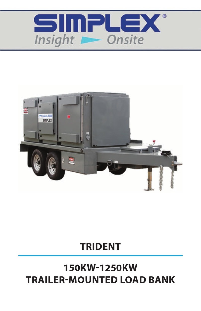
Simplex LBD Series User manual

LOAD BANK
TECHNICAL MANUAL
(LBD Series)
Customer: XXXXXX
Work Order: XXXXX-XX-XX
Model: LBD XXX
April 2011
The information herein is the property of Simplex, Inc. and/or its subsidiaries.
Without written permission, any copying, transmitting to others, and other use
except that for which it is loaned, is prohibited.
(File: Lbdman8p.indd)

Simplex, Inc., 5300 Rising Moon Road, Springfield, IL 62711-6228 • 217-483-1600 • Fax 217-483-1616
Lbdman8p.indd (04/11) • © 2011 Simplex, Inc. All Rights Reserved. • Printed in the USA. • www.simplexdirect.com
LOAD BANK MANUAL • LBD Series • page 1 of 16
Contents
DESCRIPTION .............................................................................. 2
Control System ...................................................................... 3
Load System........................................................................... 3
PRIMARY INSPECTION ............................................................... 4
INSTALLATION............................................................................. 4
OPERATION.................................................................................. 5
Manual..................................................................................... 5
Automatic ............................................................................... 5
Load Dump ............................................................................. 7
COOLING FAILURE SUBSYSTEM .............................................. 7
MAINTENANCE ............................................................................ 7
Each Operation ...................................................................... 7
Every 50 Hours or 6 Months ................................................. 8
TROUBLESHOOTING .................................................................. 8
Cooling Failure Indicated ...................................................... 8
Test Meters Do Not Operate Properly .................................. 8
Some Load Steps Cannot Be Energized.............................. 8
DRAWINGS AND PARTS LIST .................................................... 9
APPENDIX A - ABBREVIATIONS USED IN THIS MANUAL..... 10
APPENDIX B - CALCULATIONS & FORMULAS ...................... 12
APPENDIX C - TORQUE VALUES............................................. 15

Simplex, Inc., 5300 Rising Moon Road, Springfield, IL 62711-6228 • 217-483-1600 • Fax 217-483-1616
Lbdman8p.indd (04/11) • © 2011 Simplex, Inc. All Rights Reserved. • Printed in the USA. • www.simplexdirect.com
LOAD BANK MANUAL • LBD Series • page 2 of 16
DESCRIPTION
Simplex LBD Series Load Banks are
a special form of stationary, resistive,
forced air-cooled Load Bank which
utilizes the air outflow of an engine
radiator for cooling of the load ele-
ments. They are specifically designed
to apply discrete, selectable electrical
load to a power source while measur-
ing the response of the generator to
the applied load. They also provide
a means for routine maintenance
exercise to assure long term reliability
and readiness of the standby genera-
tor. Exercise Load Banks eliminate
the detrimental effects of unloaded
operation of diesel engine generators.
Simplex LBD Series Load Banks are
intended for use with water cooled
engine generator sets equipped
with unit mounted radiators. These
Load Banks are built per customer
specifications and can be installed
in numerous ways, including direct
bolted attachment to the radiator,
mounting within an air duct, wall
mounting over the air outflow open-
ing, indoors or outdoors.
Power source testing is accom-
plished by applying resistive load
steps at unity (1.0) power factor.
See the Load Bank Specifications
Sheet in the front of this manual for
the rating of your Load Bank.
Load application is by magnetic
contactor. All load branch circuits
are protected by 200,000AIC class-
T fuses.
The Control Panel contains the fol-
lowing controls and indicator lamps:
1. Over Temperature and Normal
Operation lamps,
2. Control Power switch and/or
pushbutton and
Part of Typical Pictorial Drawing
3. Master Load and load step switch-
es.

Simplex, Inc., 5300 Rising Moon Road, Springfield, IL 62711-6228 • 217-483-1600 • Fax 217-483-1616
Lbdman8p.indd (04/11) • © 2011 Simplex, Inc. All Rights Reserved. • Printed in the USA. • www.simplexdirect.com
LOAD BANK MANUAL • LBD Series • page 3 of 16
This Load Bank is protected against
cooling failures (high exhaust air tem-
perature which could damage the Load
Bank or present a safety hazard to the
operator). The “Normal Operation”
lamp illuminates when Control Power is
available and the Cooling System is op-
erating properly. When a cooling failure
occurs the automatic safety features in
the Control System immediately remove
the load from the test source and illu-
minates the “Over Temperature” lamp.
The malfunction must be corrected and
the Load Bank must be reset by turning
the Load Bank “Off” then “On” before
the load can be re-applied.
The Load Bank consists of two principal
systems:
1. Control System
2. Load System
CONTROL SYSTEM
The Control System allows the opera-
tor to apply a desired load to the test
source and measure the response of
the test source to the load. This system
also contains the circuitry utilized to
disconnect the Load Bank from the test
source in the event of cooling failures
and/or improperly positioned operating
controls. The Control System consists
of switches and lamps located on the
Control Panel and logic circuitry located
in the Control Section.
Control power (120V) is supplied to
the Load Bank by one of the following
methods:
1. test source via a control power trans-
former,
2. test source line to neutral, or
3. external source.
LOAD SYSTEM
Simplex LBD Series Load Banks are
built up in fused branch circuits of not
more than 70A each and protected by
600V, 200,000AIC class-T fuses. All
wiring and devices within the branch
circuit are rated in accordance with the
fuse rating. Branch circuit fusing of the
elements virtually eliminates the danger
of short circuit of the load elements and
consequent catastrophic damage to the
Load Bank.
These Load Banks utilize either the
Simplex Pow'r Rod or the Simplex Pow'r
Web load elements. See Parts Legend
Drawing for specific elements used.
Pow'r Rod Load Elements
Simlpex Pow'r Rod Load Elements are
UL recognized. These elements are
totally enclosed, sealed and weath-
erproof. Pow'r Rod elements consist
of nickel-chromium resistance wire
electrically insulated and sealed within
a metallic sheath. The hazard of electric
shock to personnel and the danger of
short circuit by foreign object penetra-
tion are reduced since the elements are
electrically dead on the outside. They
will not fatigue from engine or air-blast
vibrations and will not sag or stretch
if overheated. The sheath material is
"incolloy", a rustproof nickel alloy with a
very high temperature rating (1600°F).
These elements do not require a cool
down period.
References to Automatic Op-
eration in this manual should be
ignored if the Load Bank you are
using is equipped with Manual
Load Step Application only.

Simplex, Inc., 5300 Rising Moon Road, Springfield, IL 62711-6228 • 217-483-1600 • Fax 217-483-1616
Lbdman8p.indd (04/11) • © 2011 Simplex, Inc. All Rights Reserved. • Printed in the USA. • www.simplexdirect.com
LOAD BANK MANUAL • LBD Series • page 4 of 16
Powr-Web Load Elements
Simplex “Powr-Web” load elements are
UL recognized. These elements conser-
vatively operate at approximately half
the maximum temperature rating of the
alloy (1080°F vs. 1920°F). For example:
Alloy: FeCrAl
Ratings: 3333W@120V
4170W@139V
Connections: 120V wye (208V),
139V wye (240V, 3ø),
277V wye (480V, 3ø),
240 delta (240V, 3ø), or
480 delta (480V, 3ø).
These elements are rigidly supported
by high-temperature, ceramic-clad,
stainless-steel supports. Element-
to-element short circuits are virtually
eliminated.
PRIMARY INSPECTION
Preventative visual inspection of the
shipping crate and Load Bank must be
performed before installation. Physical
or electrical problems due to handling
and vibration may occur during ship-
ment.
1. If crate shows any signs of damage
examine the Load Bank in the cor-
responding areas for signs of initial
problems.
2. Check the entire outside of the
cabinet for any visual damage which
could cause internal electrical or
mechanical problems due to reduced
clearance.
3. Rotate and push all switches
through all positions to en-
sure smooth operation.
4. Inspect the bottom of crate/
enclosure for any compo-
nents that may have jarred
loose during shipment such
as indicator light lenses,
switch knobs, etc.
5. Visually inspect element
chamber for foreign objects
and mechanical damage.
INSTALLATION
1. Using the flanges provided
attach the Load Bank with
bolts per specifications.
Bottom support for the load
element enclosure is recommended.
2. Confirm the test source is properly
grounded and ground the Load Bank
to its own independent ground.
3. Confirm all load command switches
are in the “Off” position.
4. Per load connection drawings cable
the load source to the Load Bank.
Consult NEC for proper wire size.
When cabling the Load Bank to the
test source pull Load Bank access
holes, install conduit connectors and
conduits as needed.
5. Connect customer supplied contacts
to load dump terminals shown on
electrical drawing or jumper if not
used.
6. Per drawings connect customer
supplied alarm contacts.
If any problems are observed
during Primary Inspection call
the Simplex Service Manager at
217-483-1600 (24hrs.)
References to Remote Control
in this manual should be ig-
nored if the Load Bank you are
using is equipped with a Local
Control Panel only.
Part of Typical
Pictorial Drawing
This manual suits for next models
1
Table of contents
Other Simplex Industrial Equipment manuals

Simplex
Simplex STS DAY TANK User manual

Simplex
Simplex Trident User manual

Simplex
Simplex 4604-9201 Quick guide

Simplex
Simplex VSH SUPER Manual

Simplex
Simplex 4090-9006 User guide

Simplex
Simplex STS User manual

Simplex
Simplex LT0290 User manual

Simplex
Simplex Full-Size Fuelport User manual

Simplex
Simplex 2120 Configuration guide

Simplex
Simplex 2120 Configuration guide