manuals.online logo
Brands
  1. Home
  2. •
  3. Brands
  4. •
  5. Simply Elegant
  6. •
  7. Lock
  8. •
  9. Simply Elegant TM Patio Lockset Series User manual

Simply Elegant TM Patio Lockset Series User manual

070-117
070-118
070-119
070-120
TM Patio Lockset
www.simplyelegantproducts.com 1
INSTRUCTIONS (Page 1 of 4)
TM PATIO LOCKSET INSTALLATION INSTRUCTIONS
1
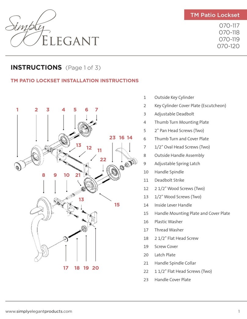
1 Outside Key Cylinder Assembly & Screws
2 Key Cylinder Cover Plate (Escutcheon)
3 Adjustable Deadbolt
4 Thumb Turn Mounting Plate
5 2" Pan Head Screws(Two)
6 Thumb Turn & Cover Plate
7 1/2" Oval Head Screws(Two)
2 3 4 5 6 7
8
910
11
12 13
14
15
16
17
20
19 21
2322
18
8 Outside Handle Assembly & Screws
9 Outside Handle Mounting Plate,
Assembly & Screws
10 Adjustable Spring Latch ( 2 3/8" to 2 3/4")
11 Inside Handle Mounting Plate & Assembly
12 1-1/2” Flat Head Screws (Two)
13 Inside Handle Cover Plate
14 Set Screw
15 Handle Spindle
16 Inside Lever Handle Assembly (Left or
Right) & Screws
17 Inside Lower Mounting Assembly for
Outside Handle
18 2-1/2" Wood Screws(Two)
19 1/2” Deadbolt Wood Screws
20 Deadbolt Strike Plate
21 Deadbolt Strike Bolt Receptacle
22 Latch Plate & Screws
23 Latch Receptacle
24 Screw Cover
24
070-117
070-118
070-119
070-120
TM Patio Lockset
www.simplyelegantproducts.com 2
INSTRUCTIONS (Page 2 of 4)
• The deadbolt is adjustable. It is set for 2-3/8” set back,
but can be adjusted to 2-3/4”. (See the instruction sheet,
“Adjustable Deadbolt & Latch.”)
• The #3 ADJUSTABLE DEADBOLT is marked with an up
arrow on the side.
• Insert the deadbolt in the up position into the top hole on
the end of the door. Screw in place using #19
BOLT WOOD SCREWS (two).
• Insert #1 OUTSIDE KEY CYLINDER into #2 KEY CYLINDER
COVER PLATE then slide the key cylinder arm through the
deadbolt where the cross slot is located.
• Hold in place while putting #4 THUMB TURN MOUNTING
PLATE on the inside. Now insert and tighten #5
HEAD SCREWS (two). Next place #6 THUMB TURN AND
COVER PLATE into the #4 THUMB TURN MOUNTING
PLATE and tighten with #7 (two).
DEADBOLT INSTALLATION
• The latch is adjustable. It is set for 2-3/8” set back, but the
latch can be adjusted to 2-3/4” set back. (See instruction
“Adjustable Deadbolt & Latch.”)
• The #10 ADJUSTABLE SPRING LATCH should be oriented so
that the beveled latch faces in the direction that the door
closes. With the orientation in the direction of closing, place
the latch in the bottom hole on the end of the door. Screw
in place using #19 (two).
LATCH INSTALLATION
DIRECTION DOOR
CLOSES
1/2” DEAD-
1/2” DEADBOLT WOOD SCREWS
1 2 3 4 5 6 7
20
19
070-117
070-118
070-119
070-120
TM Patio Lockset
www.simplyelegantproducts.com 3
INSTRUCTIONS (Page 3 of 4)
• Locate the tread hole for the bottom of #8 OUTSIDE HANDLE ASSEMBLY &
SCREWS by measuring from the center of the bottom hole 7-1/2”. Then drill
a 5/16” hole through the active door.
HANDLE INSTALLATION
.
7-1/2”
070-117
070-118
070-119
070-120
TM Patio Lockset
www.simplyelegantproducts.com 4
INSTRUCTIONS (Page 4 of 4)
HANDLE INSTALLATION
Slide #11 INSIDE HANDLE MOUNTING PLATE &
ASSEMBLY into the #16 INSIDE LEVER HANDLE
ASSEMBLY (LEFT OR RIGHT) & SCREWS. The collar
should be put on from the long end moving the
collar toward the short end. Now from the inside
of the door insert the short end of #11 INSIDE
HANDLE MOUNTING PLATE & ASSEMBLY
through #10 ADJUSTABLE SPRING LATCH.
Place the top of #8 OUTSIDE HANDLE ASSEMBLY
& SCREWS into the bottom hole sliding #8
OUTSIDE HANDLE ASSEMBLY & SCREWS into #10
ADJUSTABLE SPRING LATCH. From the inside,
place #11 INSIDE HANDLE MOUNTING PLATE &
ASSEMBLY and screw to #8 OUTSIDE HANDLE
ASSEMBLY & SCREWS using #12 1-1/2” FLAT HEAD
SCREWS (two).
Attached #13 INSIDE HANDLE COVER PLATE to #11 INSIDE HANDLE MOUNTING PLATE & ASSEMBLY by pressing on and
securing with #14 SET SCREW.
Place #16 INSIDE LEVER HANDLE ASSEMBLY (LEFT OR RIGHT) & SCREWS onto the #15 HANDLE SPINDLE and tighten the
#14 SET SCREW from below using the Allen wrench provided. NOTE: Two handles - both left-hand and right-hand - are
provided.
Now secure the bottom of #8 OUTSIDE HANDLE ASSEMBLY & SCREWS by inserting the #17 INSIDE LOWER MOUNTING
ASSEMBLY FOR OUTSIDE HANDLE.
Place #24 SCREW COVER onto the inside bottom mounting assembly.
•
•
•
•
•
•
8
910
11
12 13
14
15
16
20
19 21
2322
18
17
24

Other Simply Elegant Lock manuals

Simply Elegant TM Patio Lockset User manual

Simply Elegant

Simply Elegant TM Patio Lockset User manual

Popular Lock manuals by other brands

LOX LOCKING EM3500FM installation manual

LOX LOCKING

LOX LOCKING EM3500FM installation manual

Roger RWL-2 operating manual

Roger

Roger RWL-2 operating manual

Abloy EL590 quick start guide

Abloy

Abloy EL590 quick start guide

Kwikset 905 Installation and user guide

Kwikset

Kwikset 905 Installation and user guide

Weiser Smartcode 10 Installation and user guide

Weiser

Weiser Smartcode 10 Installation and user guide

Stanley BEST ACCESS SYSTEMS 45HM Series quick start guide

Stanley

Stanley BEST ACCESS SYSTEMS 45HM Series quick start guide

Snug Cottage Hardware Borglocks BL3400 installation guide

Snug Cottage Hardware

Snug Cottage Hardware Borglocks BL3400 installation guide

Motor Yamaha 10-300C installation instructions

Motor

Motor Yamaha 10-300C installation instructions

Glutz Piatto Fixing instructions

Glutz

Glutz Piatto Fixing instructions

Kaadas KA210 installation guide

Kaadas

Kaadas KA210 installation guide

HPE EdgeConnect EC-S-P installation guide

HPE

HPE EdgeConnect EC-S-P installation guide

Digilock NEXT Sola3 Keypad Product guide

Digilock

Digilock NEXT Sola3 Keypad Product guide

SECO-LARM Enforcer E-941SA-300 installation manual

SECO-LARM

SECO-LARM Enforcer E-941SA-300 installation manual

Stealth STL-HHS-BIO instructions

Stealth

Stealth STL-HHS-BIO instructions

Alarm Lock 260 Installation & operating instructions

Alarm Lock

Alarm Lock 260 Installation & operating instructions

steute EX STM 515 Mounting and wiring instructions

steute

steute EX STM 515 Mounting and wiring instructions

Burg Wächter secuENTRY Home 5001 PIN Initial setup

Burg Wächter

Burg Wächter secuENTRY Home 5001 PIN Initial setup

Resource SDGF-001 Quick operation guide

Resource

Resource SDGF-001 Quick operation guide

manuals.online logo
manuals.online logoBrands
  • About & Mission
  • Contact us
  • Privacy Policy
  • Terms and Conditions

Copyright 2025 Manuals.Online. All Rights Reserved.